

Page 1
MARKING METHODS, INC.
301 SOUTH RAYMOND AVENUE
ALHAMBRA, CA 91803-1531
626-282-8823
FAX 626-576-7564
Email: [email protected]
Website: www.markingmethods.com
MANUAL FOR
ELECTRO-CHEMICAL
MARKING, EQUIPMENT
& SUPPLIES
®
ATTENTION:
PLEASE READ MANUAL
CAREFULLY BEFORE
OPERATING EQUIPMENT
INC
MARKING METHODS, INC.
MODEL MARK 300 (SERIES)
EQUIPMENT
•
OPERATION
•
ELECTROLYTE CHART
•
SUPPLIES
•
®
Page 2
WHAT IS ELECTRO-CHEMICAL MARKING?
ELECTRO-CHEMICAL MARKING is the process used for stress free permanent marking on all con-
ductive metals. The process is economical, simple, fast and safe. The one restriction to this process is
that it will not function on painted parts, already anodized aluminum or through certain heavy phosphate
coatings. However, by deep etching the parts prior to any of these non-conductive coatings, the mark
shows through very legibly. This allows positive traceability throughout the life of the parts.
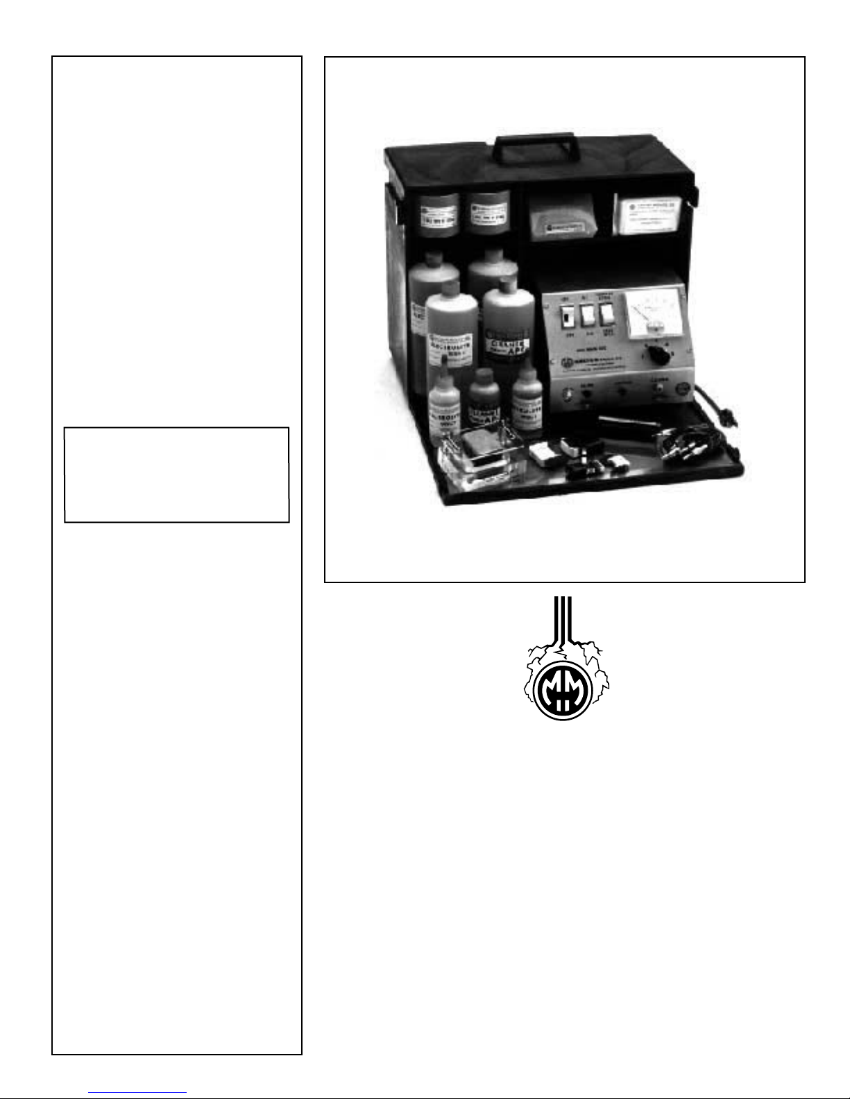
MARKING METHODS’ complete MARK 300 (SERIES) Electro-Chemical marking system is designed
to provide maximum performance and ease of operation. The assembly includes all the necessary equip-
ment and supplies to most effectively mark all parts....from tiny semiconductors to massive aircraft and
aerospace components. Depth of mark from one ten thousandth (.0001) of an inch deep for feeler and
plug gages to ten thousandths (.010) deep for absolute traceability of parts is easily attainable.
The power unit is equipped with an AC-DC switch. The AC (alternating current) alternately etches out
and redeposits back a combination of the metal oxide and electrolytic salts producing a black mark. The
DC (direct current) charges the applicator negatively (cathodic) which dissolves metal out, etching a
frosted or clear mark. To prevent corrosion, the parts must be thoroughly cleaned after marking to remove any residual salts. No special skill is required to operate the equipment except pride in doing a
good job. Electro-Chemical marking does not deform, weaken or fracture the metal because molecular
structure is not altered beyond the depth of the mark. Methods such as steel stamping, electric arc etching or vibratory marking alter the grain structure of the metal in the area of the mark causing possible
stress or fracture to the parts.
15
10
0
5
AMPERES
2
1
CLEANER
RED
20
25
AC.
3
4
5
YELLOW
E
NORMAL
AC
ETCH
ON
DEEP
DC
ETCH
OFF
MARK 300
MODEL
MARKING METHODS, INC.
ALHAMBRA, CALIFORNIA
INC
ELECTRO-CHEMICAL, LASER MARKING SPECIALISTS,
T
H
O
S
U
P
R
E
E
S
B
1
GROUND
MARK
T
BLACK
A
3
2
HOW DOES THE PROCESS WORK?
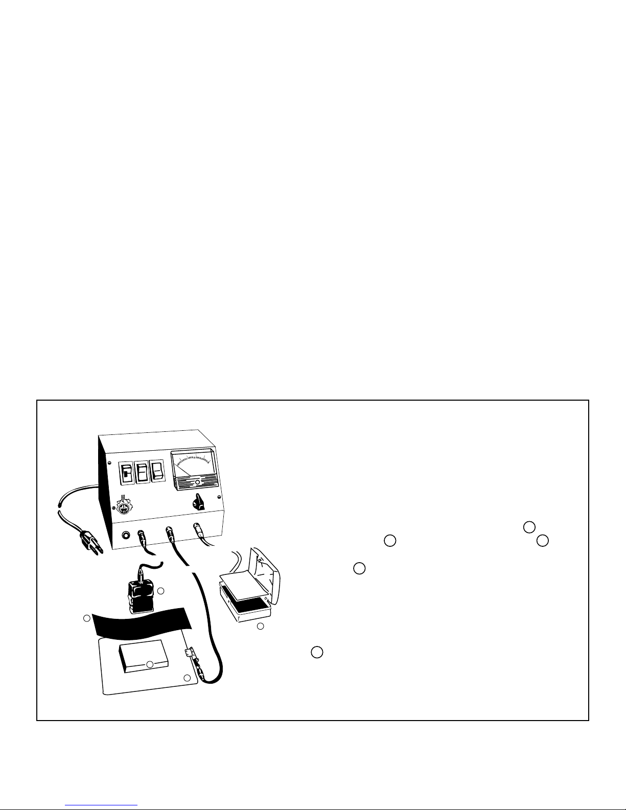
A controlled depth, permanently etched mark of any
design or detail is made by the operator on metal
surfaces in a matter of seconds. It is simply made
by placing the MARKING APPLICATOR A over
the STENCIL B in contact with the PART C to
be marked. The part is positioned on a GROUND
PLATE D to complete the electrical current. The
-
current and the electrolyte fluid do the rest
seconds! A permanent mark is the result which can
only be removed by buffing or grinding the metal
down to the depth of the mark. Occasional blotting
in
of the applicator in the STENCIL CLEANER TRAY
3
2
1
C
D
E replenishes the electrolyte supply and helps
to keep the stencil apertures clean.
-1-
Page 3
NORMAL-ETCH
INSTRUCTIONS for using MARK 300 POWER UNIT
(1) Plug the line cord connected to the power unit into a grounded 110/120 VAC outlet only. Converters are available
for 220/240 VAC.
(2) Plug the BLACK cord into the BLACK (MARK) receptacle; the opposite end of the cord into the HAND PAD.
(3) Plug the RED cord into the RED (GROUND) receptacle; the opposite end to the GROUND PLATE or attach the alligator
clip directly to the part to be identified.
(4) Plug the YELLOW cord into the YELLOW (CLEANER) receptacle; the opposite end to the STENCIL CLEANER TRAY.
(5) Set the AC-DC Switch on AC position for most metals and DC for Aluminum and Black Oxide. AC produces a black
mark; DC produces a frosted or clear mark.
(6) Set the Normal/Deep-Etch Switch on NORMAL.
(7) Set the Rheostat on No. 5. If the mark is blurred, turn the Rheostat
to a lower position.
(8) Place a clean Hand Pad Screencloth on the Hand Pad. Saturate
the Screencloth with the proper Electrolyte. Select the proper
Electrolyte from the chart on page 5.
Refer to applicable MSDS for safety information.
NOTE: Fresh Electrolyte and a clean Screencloth are essential.
Saturate the Cleaner Tray Wick with the same Electrolyte used on
the Screencloth. Blot the Hand Pad in the Cleaner Tray to add fresh
Electrolyte. Use paper towels to blot off any excess Electrolyte on
the Screencloth. (It should be saturated but not dripping).
REPLACE SCREENCLOTH WHEN IT BECOMES CONTAMINATED
OR FAILS TO GIVE GOOD SHARP MARKS.
(9) Position the Stencil on the part to be identified so the legend reads
correctly and hold securely so the legend does not move.*
NOTE: If the Stencil is positioned on the Hand Pad for a single blot,
the legend should read reversed and be secured by a Retainer Ring.
(10) Set the ON-OFF Switch to ON position.
(11) Blot over the legend in the Stencil with the Hand Pad for approximately
2 seconds, then break contact by raising the Hand Pad from the
part momentarily. Continue the procedure until the desired darkness
and/or depth is obtained.
(12) To clean Stencil during marking, place the Stencil on the Cleaner
Tray Wick and blot over the image with the Hand Pad.
(13) After the desired darkness or depth is reached, remove the Stencil
from the part and using the APC Cleaner, thoroughly clean the part
with a clean shop cloth by using a rubbing action, making sure that
none of the Electrolyte is left on the part.
NOTE: For best results pour some of the Cleaner into a small open
container instead of using the Cleaner from the bottle. This will
prevent contamination of the fresh Cleaner. Parts may also be immersed in the APC Cleaner.
CAUTION: IF THE PARTS ARE IMMERSED, CHANGE CLEANER WHEN IT BECOMES
CONTAMINATED WITH ELECTROLYTE. WHEN THIS HAPPENS THE CLEANER WILL BECOME CLOUDY.
(14) After cleaning the part, dry it thoroughly with a clean, dry cloth.**
(15) After the marking is completed, turn the ON-OFF Switch to OFF. Unplug the BLACK, RED and YELLOW cords from
their receptacles.
(16) Remove the Screencloth from the Hand Pad and flush thoroughly with cold water. The Screencloths are reusable if
they rinse out reasonably clean.
(17) With water, thoroughly rinse the Hand Pad, Retainer Ring, Insulator, Ground Plate and any other material that came
in contact with the Electrolyte.
(18) Dry the above mentioned items with a clean dry cloth.
(19) Discard all used Electrolyte and Cleaner.
NOTE: Never pour used Electrolyte or Cleaner back into the bottles as the oxidation from the parts will contaminate
the fresh solutions.
(20) After all these steps have been followed, your equipment and supplies will be ready for use the next time.
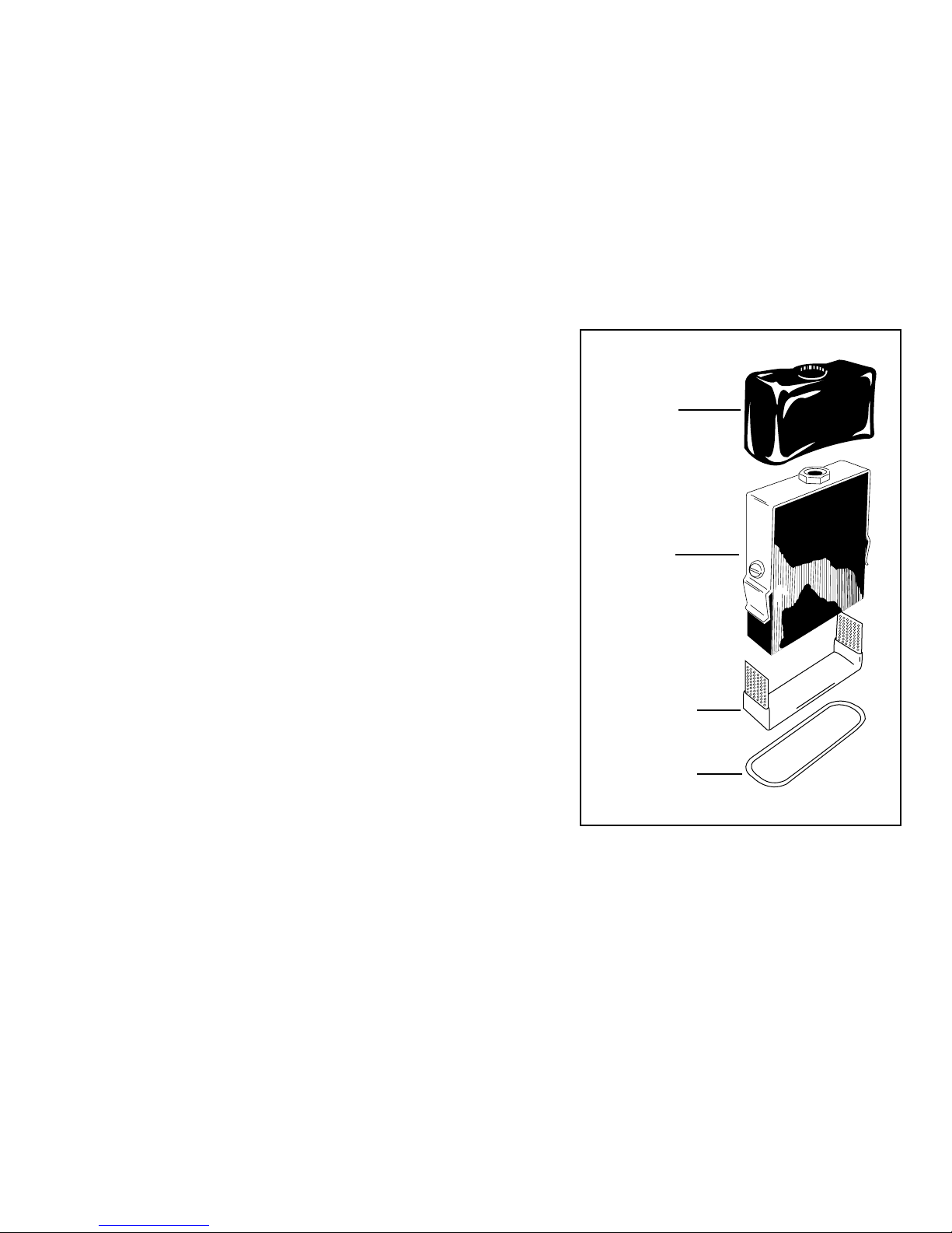
INSULATOR
HPI
HAND PAD
HP
SCREENCLOTH
HPS
RETAINER RING
HPR
* See back cover for Die-Impression Stencil instructions.
** Use CPO or WSP for highly corrosive metal parts, after cleaning and drying part.
-2-
Page 4
DEEP-ETCH
INSTRUCTIONS for using MARK 300 POWER UNIT
(1) Plug the line cord connected to the back of the power unit into a 110/120 VAC outlet only. Converters are available on
request for 220/240 VAC.
(2) Plug the BLACK cord into the BLACK (MARK) receptacle; the opposite end of the cord into the Deep-Etch Hand Pad.
(3) Plug the RED cord into the RED (GROUND) receptacle; the opposite end to the Ground Plate or attach the alligator clip
directly to the part to be identified.
(4) Plug the YELLOW cord into the YELLOW (CLEANER) receptacle; the opposite end into the STENCIL CLEANER TRAY
receptacle.
(5) Set the AC-DC Switch on DC position.
(6) Set the Normal/Deep-Etch Switch on DEEP-ETCH.
(7) Set the Rheostat to No. 3.
(8) Set the ON-OFF Switch to ON position.
(9) Place a clean Wick on the Deep-Etch Hand Pad and secure the Wick
with a Retainer Ring. Saturate the Wick with the proper Electrolyte.
(Select the proper Electrolyte from the Deep-Etch column of the chart
on page 5). NOTE: Fresh Electrolyte and a clean Wick are essential.
Saturate the Cleaner Tray Wick with the same Electrolyte used on the
Wick. Blot the Hand Pad in the Cleaner Tray to add fresh Electrolyte.
Use paper towels to blot off any excess Electrolyte. USE A DEEP-
HAND PAD
HP
WICK
HPW
RETAINER RING
HPR
(14) To clean the Stencil before marking the next part, place the Stencil on the Cleaner Tray Wick and blot over the image
with the Hand Pad.
(15) After the marking is completed, turn the ON-OFF switch to OFF . Unplug the BLACK, RED and YELLOW cords from their
receptacles.
(16) Remove the Wick Pad from the Hand Pad and DISCARD ALL USED WICKS.
(17) Take the Hand Pad, Retainer Ring, Ground Plate and any other material that came in contact with the Electrolyte and
rinse thoroughly with water.
(18) Dry the above mentioned items with a clean dry cloth.
(19) Discard all used Electrolyte and Cleaner.
NOTE: Never pour used Electrolyte or Cleaner back into the bottles as the oxidation from the parts will contaminate the
fresh solutions.
(20) After all these steps have been followed, your equipment and supplies will be ready for next time.
ETCH WICK PAD FOR EACH ONE OR TWO PARTS.
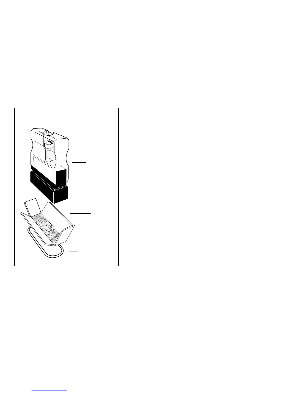
(10) Position the Stencil on the part to be identified so that the legend reads
correctly and hold securely so the legend does not move.*
(11) Blot over the Stencil with the Hand Pad 4 or 5 times, then dip the Hand
Pad into the Cleaner tray. The dwell time for each blotting should be
approximately 2 to 3 seconds on, then break contact by raising the
Hand Pad from the part momentarily. Continue the procedure 15 to 20
times or until the desired depth is obtained. (.003 to .006” deep
normally takes from 1 to 2 minutes.)** NOTE: Be sure the Stencil is
held securely and does not move during marking as this can cause
multiple marks. The blotting action should be as follows: 2 to 3 seconds
dwell ON the part, 1 second OFF the part. This allows the gases to
escape and affords a pulsing effect.
(12) After the desired depth is obtained, remove the Stencil from the part
and using the APC Cleaner, thoroughly clean the part with a shop cloth
by using a hard rubbing action, making sure that none of the Electrolyte
is left on the part. NOTE: For best results pour some of the Cleaner
into a small open container instead of using the Cleaner from the
bottle. This will prevent contamination of the fresh Cleaner.
(13) After cleaning the part thoroughly, dry it with a clean dry cloth.***
* See back cover for Die-Impression Stencil instructions.
** To produce a DARK Deep-Etch mark, set the AC-DC Switch on AC position and the Normal/Deep-Etch Switch on NORMAL ETCH. Blot
over the Stencil again using fresh Electrolyte on the Hand Pad. This is done after the desired depth is achieved.
*** Use CPO or WSP for highly corrosive metal parts, after cleaning and drying part.
-3-
Page 5
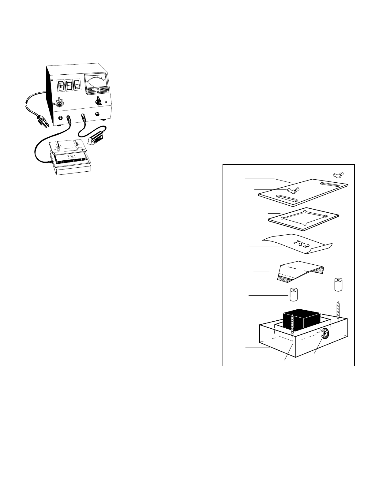
BENCH FIXTURES
INSTRUCTIONS
for using BF1520, BF2045 & BF4060
BENCH FIXTURES
with MARK 300 POWER UNIT
15
NORMAL
AC
ON
DC
OFF
MARK 300
MODEL
MARKING METHODS, INC.
INC
ALHAMBRA, CALIFORNIA
ELECTRO-CHEMICAL, LASER MARKING SPECIALISTS,
MARK
T
H
O
S
U
P
R
T
E
E
S
10
20
5
ETCH
DEEP
ETCH
GROUND
25
AMPERES
0
AC.
3
4
2
5
1
CLEANER
(6) Set the Rheostat on No.5. Note: If the mark is blurred, turn the
Rheostat to a lower position.
(7) Place a clean Wick Pad on the graphite block in the Bench Fixture
(green side down) and secure the Wick with a Retainer Ring.
(8) Saturate the Wick Pad with the proper Electrolyte. Select the
proper Electrolyte from the chart on page 5.
(9) Place Stencil with the legend reading REVERSED over Wick Pad
and secure a second Retainer Ring. (Stencil may also be secured
by a Locating Plate, which is milled to fit the part).*
(10) Set the ON-OFF Switch to ON position.
(11) Place part to be marked in fixture and ground by touching part
with either the Hand Ground, Finger Ground, or with the alligator
clip. NOTE: Etching may be accomplished by rolling the part
across the stencil with Hand Ground or by placing the part in the
Locating Plate and grounding with the Hand Ground or Finger
Ground.
(12) After marking each part, thoroughly clean the parts with APC
Cleaner by wetting a clean shop cloth with the Cleaner and
rubbing the part, making sure that none of the Electrolyte is left
on the part, or by immersing the part in a small open container
filled with APC Cleaner.
(13) After cleaning the parts thoroughly , dry them with a clean dry cloth.
(14) After marking is completed, turn the ON-OFF switch to OFF.
Unplug the BLACK and RED cords from their receptacles.
(15) Remove the Wick Pad from the graphite block and wash
thoroughly with water. Wick Pads are reusable if they wash out
reasonably clean.
(16) With water, thoroughly rinse the Bench Fixture, Retainer Rings, Hand Ground and any other material that came in
contact with the Electrolyte.
(17) Dry the above mentioned items with a clean, dry cloth.
(18) Discard all used Electrolyte and Cleaner. NOTE: Never pour used Electrolyte and Cleaner back into the bottles as
the oxidation from the parts will contaminate the fresh solutions.
(19) After all these steps have been followed, your equipment and supplies will be ready for use the next time.
(NORMAL ETCH ONLY)
(1) Plug the line cord connected to the back of the Power Unit into a 110/120
VAC outlet only. Converters are available on request for 220/240 VAC.
(2) Plug the BLACK cord into the BLACK (MARK) receptacle: the opposite
end of the cord into the Bench Fixture.
(3) Plug the RED Cord into the RED (GROUND) receptacle; slide the alligator
clip off the opposite end and slide on the Hand Ground.
(4) Set the AC-DC Switch on AC for most metals and DC for Aluminum and Black
Oxide. AC produces a black mark; DC produces a frosted or clear mark.
(5) Set the Normal/Deep-Etch Switch on NORMAL.
LOCATING
PLATE
WING NUT
RETAINER RING
STENCIL
WICK PAD
SPACER
MARKING
BLOCK
BENCH
FIXTURE
BASE
SCREWS
RECEPTACLE
BOLT
* See back cover for Die-Impression Stencil instructions.
-4-
Page 6
ELECTROLYTES
MARKING METHODS' laboratory controlled Electrolytes are the result of years of research and development. They are carefully
formulated and cataloged by formula and batch number to mark varied metals and surface treatments. The Electrolytes are
buffered salt solutions, pH balanced, and are completely harmless to parts and surrounding equipment when used as directed.
METALS, ALLOYS & PLATINGS
ELECTROLYTE
FOR
Aluminum (most alloys)
Aluminum with high magnesium or silica
Aluminum (to be anodized)
Aluminum Bronze
Beryllium
Beryllium Copper
Black Oxide on Steel
Black Oxide on Stainless
Black Phosphate
Brass & Bronze
Cadmium Plate on Steel
Carbides
Chrome Plate-hard
Chrome Plate-decorative
Cobalt Alloys, Stellites
Copper & alloys
Copper Nickel ( cupro-nickel)
Damascus
Discaloy
Dow coating (Parkerized)
Electroless Nickel Plate
Gold and Gold Plate
Gold and Gold Plate
Hastelloy
Haynes 25 (Stellite)
Haynes 188
Inconnel
Inconnel 718 & 750
Invar
Iron
Lead and alloys
Magnesium & alloys
Molybdenum
Monel & K Monel
Nickel & alloys
Nickel Plating on Brass & Copper
Nickel Plating on Steel & Aluminum
Nickel Silver
Niobium
Nitraloy
Silver & Sterling
Silver Plate
Sintered Copper Tin
Stainless Steel (300 & 400 series)
Steels-low carbon & mild
Steels-high alloy, tool & saw steel
Tin & Tin Plate
Titanium
Titanium Nitrate
Tungsten (pure)
Tungsten Carbide
Waspaloy
Zinc & Zinc Plate
Zirconium
NUCLEAR GRADE ELECTROLYTES (non-chloride or halogen free) can be furnished that contain less then 250 ppm of chlorides (halogens), sulfur, mercury, copper, zinc, and
lead. These Electrolytes can be certified to meet MIL STD's 767 and 792 when requested.
Use a light oil film (CPO) prior to marking on sand or grit blasted surfaces to prevent blurring. Oil fills the open grain surface of the metal. This procedure is also very effective
before marking metals or plating that stain easily. Do not use gold (DF2) stencil for this application.
Submit sample parts to our laboratory for Electrolyte evaluation of particularly difficult applications.
*NOTE: POWER UNIT SETTINGS FOR ALL DEEP ETCH MARKING SHOULD BE DC AND DEEP ETCH WITH RHEOSTAT AT 3 OR HIGHER. AMPLE ELECTROLYTE MUST
ALWAYS BE USED. DEEP ETCHING MAY PRODUCE A FUZZY OR BLURRED MARK. A LIGHT BUFFING AFTER CLEANING WILL SHARPEN THE LINE DEFINITION.
See applicable MSDS for safety information.
A10
MSC1, MSC5
B20, B10
B20, MSC7, F10
B20
MSC3, F30
MSC1
F30
B20, MSC5, B10
MSC5,B20, B10, F20
C30, C10, MSC4
MSC1, MSC7
MSC1, MSC4, MSC7
MSC1, F10, F30, MSC7
B20,B10,MSC3,MSC5
MSC5, F30, F20, B20
C10 , MSC4
MSC4, F30
MSC7 OR F30
MSC1, F10, C10
MSC4, MSC3, F20
MSC7, MSC1,MSC4
MSC5, F10
MSC4, C10, F20
MSC4, F30, F10
MSC4, MSC7, MSC1,F30
MSC4, F10
MSC3, F30
MSC5, MSC1
F10, C10
MSC1, C10
MSC7, F30
MSC7, B20, C10
MSC4, F30, F20
MSC5, B20, F20
MSC3, T10
MSC4, C10
MSC8, B10
B10, B20
MSC1, MSC4, MSC7,B20
MSC4, MSC1, C10, B20
MSC4, C10
MSC5, F20
T10, MSC7, C10
MSC2
T10, F20, C30
C30, MSC4
MSC3, B10
MSC2, MSC1, B10, F20
T10, C10
NORMAL ETCH
POWER UNIT
DC
DC
DC
AC
AC
AC
DC
DC
DC
AC
AC
AC
DC
AC
AC
AC
AC
AC
AC
DC
AC
AC
DC
AC
DC
AC
AC
AC
AC
AC
AC
AC
AC
AC
AC
AC
AC
AC
AC
AC
DC
AC
AC
AC
AC
AC
AC
AC
AC
AC
AC
AC
AC
AC
COLOR
SETTING
OF MARK
Black
MSC1
White
MSC1
Black
MSC1
Black
MSC3, MSC5
Black
MSC3, MSC5
Black
MSC3, MSC7
White
White
White
Black
MSC3, MSC5
Black
Black
F30
Clear
F30
Black
Black
MSC7, MSC4
Black
MSC5, MSC3
Black
Dark
C10, MSC4
Black
Clear
C10
Dark
Dark
Clear
MSC1,F10,C10
Black
MSC4
Clear
MSC7
Black
MSC7
Black
MSC4
Black
MSC4, 59NC
Dark
Black
MSC4
Black
Clear
MSC1
Black
Black
Black
Black
Black
Black
Dark
Black
B10
Black
B10
Black
Black
MSC1
Black
MSC4, C10, MSC1
Black
MSC4, C10
Black
Dark
MSC3,F30,F20
Dark
Dark
B10,59NC,MSC3,F30
Dark
Dark
Black
Dark
MSC1
ELECTROLYTE
FOR
Allow a few seconds for color to develop before cleaning
DEEP ETCH *
Black not possible unless lacquer filled
Deep etch BEFORE anodizing (minimum .002)
Reduce amperage if blurring occurs
Use low amperage, oil part after cleaning
Use low amperage
If coating is heavy, parts should be deep etched
Allow time for oxide to stabilize before cleaning
Blotting action improves frosted contrast
Deep etch BEFORE unless coating is very thin
Dark mark usually not stable
Use minimum amount of Electrolyte (work dry)
Use high amperage
Use low amperage, work dry, wait before cleaning
Use low amperage & minimum Electrolyte
Use low amperage & minimum Electrolyte
Use DC if AC not dark enough & minimum Electrolyte
Use DC if AC not dark enough
Allow time for oxide to stabilize before cleaning
COMMENTS
MARKING METHODS, INC. ALHAMBRA,CA 91803-1531 • 626-282-8823 • FAX 626-576-7564 • email: [email protected] • VISIT OUR WEB SITE AT: www.markingmethods.com
®
© COPYRIGHT 1975
______________________________
Page 7
HP12575
HP12515
HP2575
HP2515
HP515
HP1020
HP2575DE
HP515DE
HP1020DE
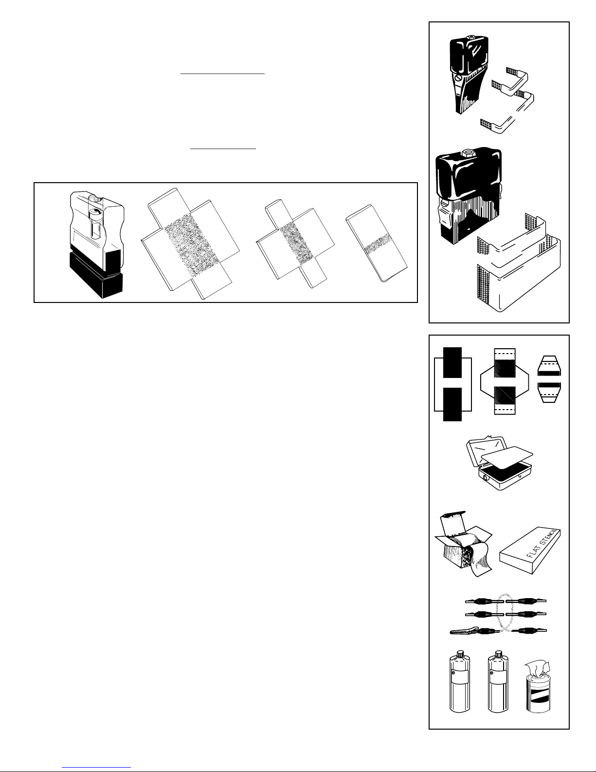
REPLACEMENT PARTS
and HAND PAD ACCESSORIES
Dimensions are actual marking area of applicator
(Pkg. of 10)
SCREENCLOTH
SCREENCLOTH
SCREENCLOTH
SCREENCLOTH
SCREENCLOTH
SCREENCLOTH
(Pkg. of 10)
WICKS
WICKS
WICKS
HAND PAD
HAND PAD
HAND PAD
HAND PAD
HAND PAD
HAND PAD
HAND PAD
HAND PAD
HAND PAD
NORMAL ETCH
1/8" x 3/4"
1/8" x 1-1/2"
1/4" x 3/4"
1/4" x 1-1/2"
1/2" x 1-1/2"
1" x 2"
DEEP ETCH
1/4" x 3/4"
1/2" x 1-1/2"
1" x 2"
DEEP ETCH WICKS
HPW
HPS12575
HPS12515
HPS2575
HPS2515
HPS515
HPS1020
HPW2575DE
HPW515DE
HPW1020DE
NORMAL ETCH
HAND PAD
1/2" x 1-1/2"
HP
1/4" x 3/4"
1/4" x 1-1/2"
SCREENCLOTH
HAND PAD
HP
HPS
HAND PAD
HP
BF1520-3
BF2045-3
BF4060-3
CT2535
CT2535-3
RO2B5
R05B5
R09B5
R12B5
R02A3
L07B5
L01B5
L08B5
L01A3
1" x 2"
1/2" x 1-1/2" 1/4" x 3/4"
BENCH FIXTURE WICK PADS
BENCH FIXTURE WICK PAD 1-1/2" x 2" (Pkg. of 10)
BENCH FIXTURE WICK PAD 2" x 4-1/2 " (Pkg. of 10)
BENCH FIXTURE WICK PAD 4" x 6" (Pkg. of 10)
OTHER ACCESSORIES
STENCIL CLEANER TRAY
STENCIL CLEANER TRAY WICK PADS (Pkg. of 10)
DIE-IMPRESSION STENCILS
DIRECTIONS FOR USE:
side of stencil with backing underneath. Remove backing to mark with stencil.
Use a typewriter set on "stencil" position. Type on colored
ROLLS
2-1/2 inch x 20 feet (Heavy duty opaque BLUE)
2-1/2 inch x 750 feet (Heavy duty opaque BLUE)
3-3/4 inch x 20 feet (Heavy duty opaque BLUE)
3-3/4 inch x 750 feet (Heavy duty opaque BLUE)
2-1/2 inch x 20 feet (Heavy duty opaque GREEN)
BOXES
3 inch x 6 inch (Heavy duty opaque BLUE)
2-1/2 inch x 7 inch (Heavy duty opaque BLUE)
3-3/4 inch x 7 inch (Heavy duty opaque BLUE)
2-1/2 inch x 7 inch (Heavy duty opaque GREEN)
(100 sheets per box)
1" x 2"
SCREENCLOTH
HPS
M
BF
R
A
G
N
I
K
I
1-1/2" x 2"
S
D
O
H
T
E
M
C.
N
4" x 6"
STENCIL CLEANER TRAY & WICK PAD
2" x 4-1/2"
BENCH FIXTURE WICK PADS
CORD SET
300
3-WIRE COLOR-CODED CORD SET
ordered in a 6 ft. length (300-6), 8 ft. length (300-8), etc.
ELECTROLYTES
SEE CHART
Available in quart bottles, 12-quart cases, 5 and 55-gallon containers. Refer to the
ELECTROLYTE CHART on page 5 for recommended formulas.
CLEANERS
APC
APCW
NO90
CPO
WSP
An ALL PURPOSE CLEANER (light amber color)
Parts cleaning wipes pre-moistened with APC cleaner
CONCENTRATED CLEANER (Milky white color) has a light oil base that leaves a
protective film on parts. (Recommended when cleaning corrosive metal parts).
CORROSION PREVENTATIVE OIL is an excellent in-plant oil for protection of parts
after they have been marked, cleaned and dried (only necessary for use on parts
that require protection from normal atmospheric conditions).
WATER SOLUBLE PROTECTANT is used in same application as CPO but contains
no solvent base.
Standard length is 3-1/2 ft., but may also be
-6-
DIE IMPRESSION STENCILS
CORD SET
INC
E
L
E
C
L
T
R
O
ELECTROLYTES & CLEANERS
INC
A
P
E
T
Y
C
C
R
L
E
E
A
N
APCW
wipes
Page 8
SPECIAL INSTRUCTIONS and ANSWERS TO PROBLEMS
PARTS BECOME FOGGY, CORRODED, CONTAMINATED OR BROWN FINGERPRINTS APPEAR.
•
MARK IS NOT LEGIBLE OR DARK ENOUGH.
•
MARK ON ALUMINUM DISAPPEARS AFTERANODIZING.
•
BLACK OXIDE WHITE MARK IS NOT LEGIBLE OR IS INCOMPLETE.
•
DEEP ETCH REQUIRES A DARK MARK.
•
POWER UNIT INDICATOR LIGHT GLOWS BUT NO MARK IS MADE.
•
Parts were improperly cleaned.
Use APC Cleaner. NEVER oil
parts without cleaning & drying
first.
Incorrect Electrolyte.
Incorrect current setting.
Dwell time too short.
Part must be DEEP-ETCHED a
minimum of .002" deep prior to
anodizing. Part cannot be
marked after anodizing.
Try a different Electrolyte.
Rub a light abrasive over mark.
Use DC current.
After etching desired depth and
before moving stencil, switch
DC to AC and DEEP ETCH to
NORMAL ETCH. Then blot
several more times.
Replace cord set.
ANY INDICATION OF OVERHEATING OR SMOKE
•
TYPING ON DIE-IMPRESSION STENCIL.
•
The MARK 300 POWER UNIT is warranted to be free from defects in material and workmanship for
a period of one year from the date of purchase. This warranty does not cover defects resulting from
accident; alteration, improper use, abuse, tampering or failure of the user to follow operating instructions.
This warranty is in lieu of all other, warranties expressed, implied or statutory and all other obligations
or liabilities of Marking Methods, Inc.
MARKING METHODS, INC.
email: [email protected] www.markingmethods.com
301 SOUTH RAYMOND AVENUE • ALHAMBRA CA 91803-1531 • (626) 282-8823 • FAX (626) 576-7564
Disconnect unit from wall
socket immediately and call
manufacturer.
Set the typewriter on stencil
position or remove the ribbon.
Type on the colored side of the
stencil, then remove the backing
to mark.
W ARRAN TY
®
CAT. NO. M3IM - 10/00
 Loading...