

Market Forge Industries STM-EX, STM-ELX, STM-E, STM-EL Owner's Manual

Your Sterilizer Experts
Manufacturing – Distribution – Maintenance- Guaranteed!
Alfa Medical 1-800-762-1586
265 Post Ave 516-280-7822
Westbury, NY 11590 516-280-7832 fax
www.sterilizers.com
eMail@sterilizers.com
The attached manual is for your records.
Go to the below web site to look for parts
http://bit.ly/Market-Forge-Sterilmatic-Parts

35 Garvey Street
Everett, Massachusetts 02149

SECTION 1 INSTALLATION INSTRUCTIONS
TABLE OF CONTENTS
INSTALLATION ........................................................................................................................................................................... 2
ELECTRICAL .............................................................................................................................................................................. 2
OUTSIDE VENTING .................................................................................................................................................................... 2
WATER-COOLED EXHAUST CONDENSER .............................................................................................................................. 2
RECORDING THERMOMETER .................................................................................................................................................. 2
TRAY SUPPORTS ...................................................................................................................................................................... 3
BAFFLE INSTALLATION ............................................................................................................................................................ 3
OPERATION CHECK .................................................................................................................................................................. 3
INSTALLATION INSTRUCTIONS FOR COLD WATER CONDENSER ....................................................................................... 4
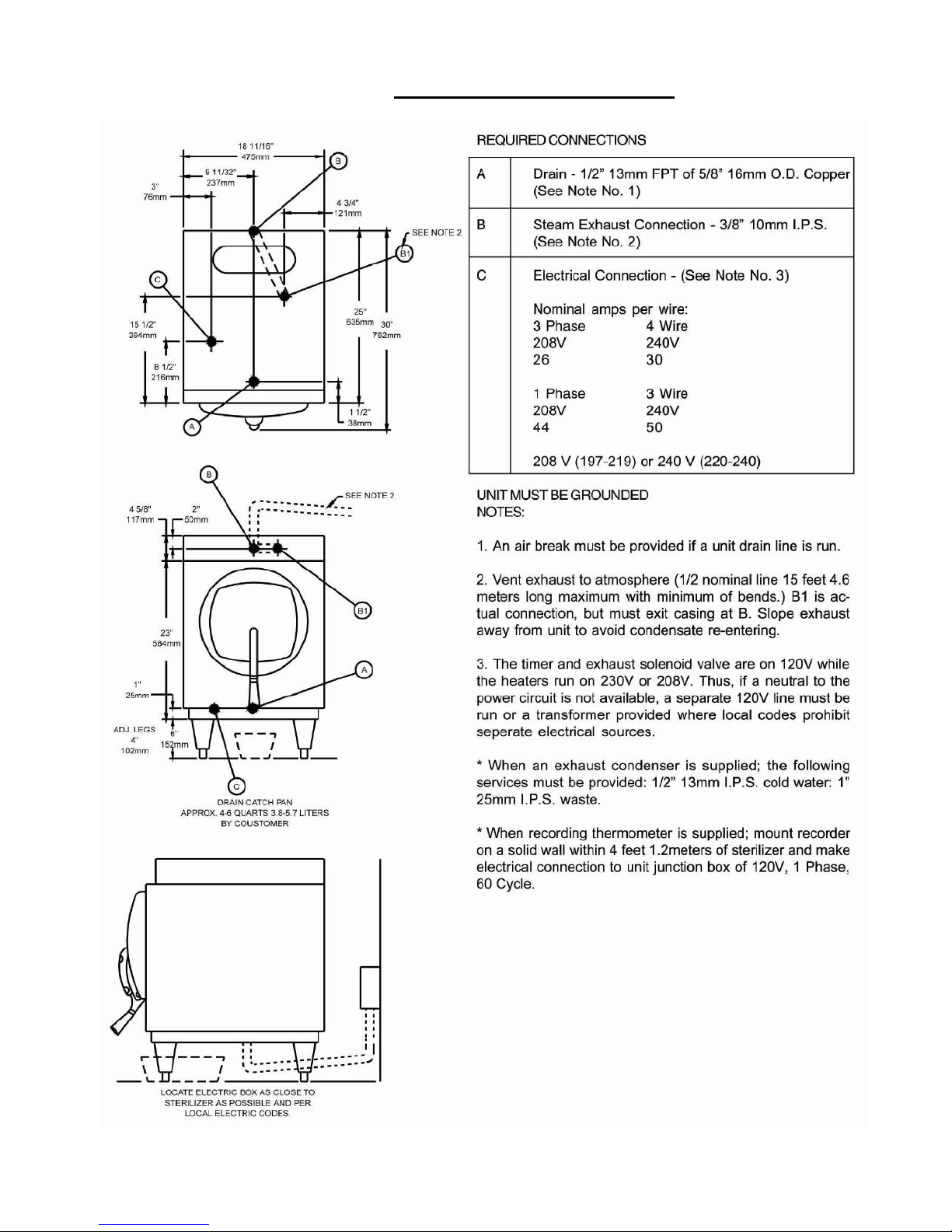
REQUIRED CONNECTIONS ...................................................................................................................................................... 5
INSTALLING PAN SUPPORTS AND BAFFLES ......................................................................................................................... 6
ELECTRICAL SUPPLY CONNECTIONS FOR STM-E AND STM-EL........................................................................................... 7
ELECTRICAL SUPPLY CONNECTIONS FOR STM-EX AND STM-ELX ..................................................................................... 7
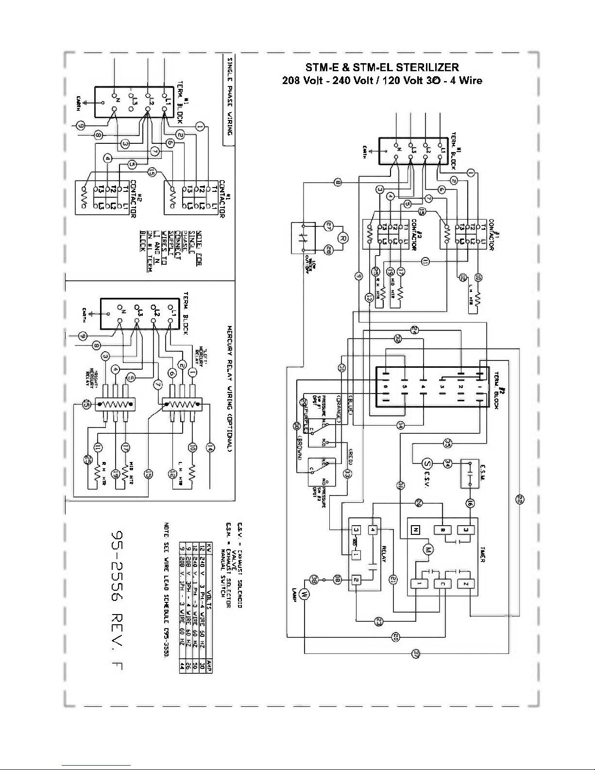
DOMESTIC WIRE DIAGRAM FOR STM-E AND STM-EL ........................................................................................................... 8
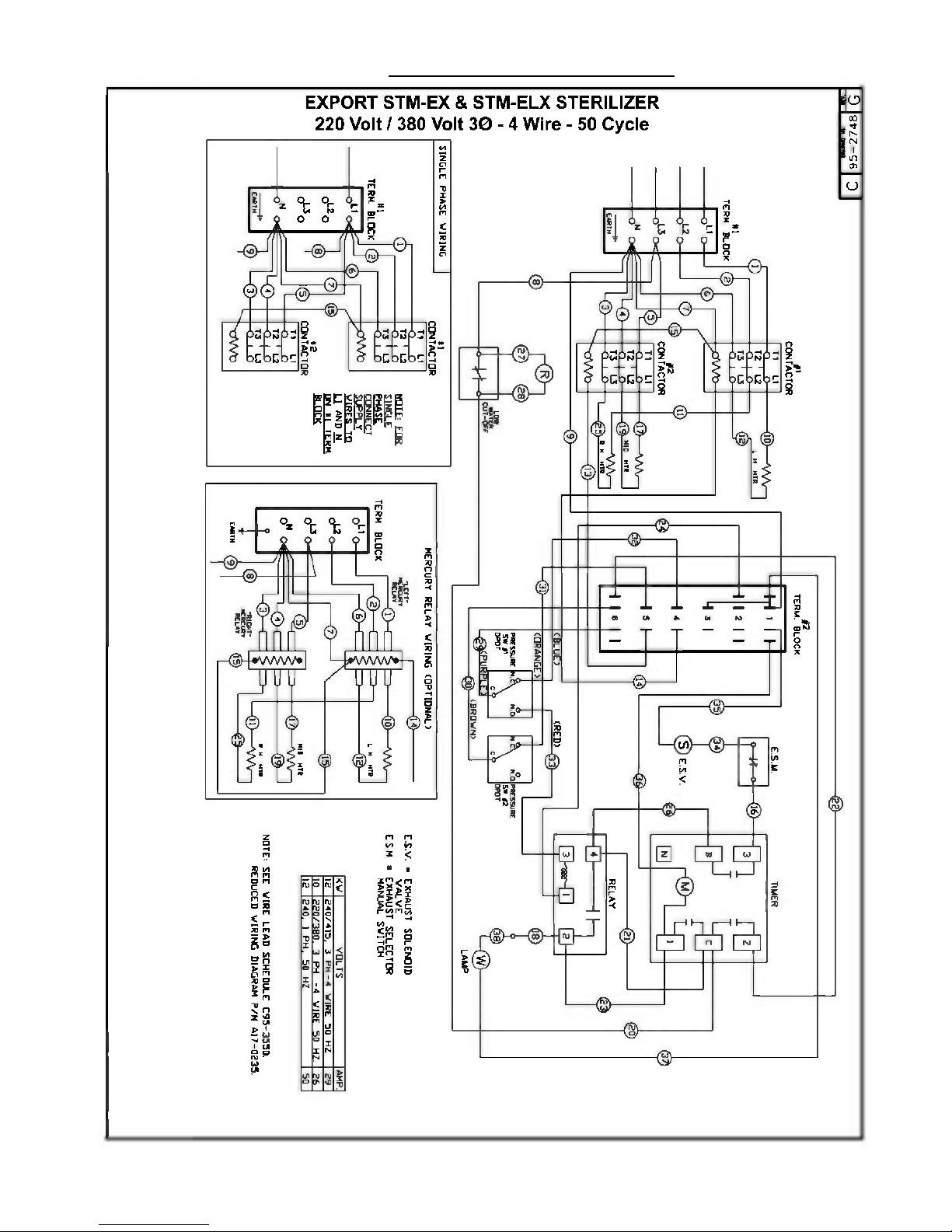
DOMESTIC WIRE DIAGRAM FOR STM-EX AND STM-ELX ...................................................................................................... 9
TYPICAL CIRCUIT CONNECTION FOR STM-E AND STM-EL ...................................................................................................10
TYPICAL CIRCUIT CONNECTION FOR STM-EX AND STM-ELX EXPORT ............................................................................... 11
INSTALLATION FOR OPTIONAL RECORDING THERMOMETER ............................................................................................. 12
TO REMOVE THE CHART .......................................................................................................................................................... 12
TO INSTALL NEW CHART .........................................................................................................................................................12
PEN ADJUSTMENT .................................................................................................................................................................... 12
REPLACEMENT PARTS FOR 24 HOUR THERMOMETER ........................................................................................................12
SECTION 2 WATER CONDITIONS ............................................................................................................................................ 13
SECTION 3 OPERATING INSTRUCTIONS
OPERATING INSTRUCTIONS ....................................................................................................................................................14
STERILIZATION GUIDE .............................................................................................................................................................15
MINIMUM STERILIZATION TIMES .............................................................................................................................................16
SECTION 4 DAILY CLEANING
DAILY CLEANING PROCEDURE ............................................................................................................................................... 16
SECTION 5 ASSEMBLY
STERILMATIC OPEN STAND .....................................................................................................................................................17
STERILMATIC OPEN STAND WITH CONDENSER ...................................................................................................................17
PARTS LIST FOR CONDENSER WITH OPTIONAL STAND ......................................................................................................17
STERILMATIC DOOR ASSEMBLY .............................................................................................................................................17
DOOR ADJUSTMENT .................................................................................................................................................................18
THE DOOR GASKET .................................................................................................................................................................. 18
DOOR LIFT SPRING ...................................................................................................................................................................18
TO REMOVE THE DOOR ASSEMBLY .......................................................................................................................................19
DOOR ASSEMBLY PARTS LIST ................................................................................................................................................19
THE FULCRUM AND DRAIN ASSEMBLY ..................................................................................................................................20
FULCRUM AND DRAIN PARTS LIST .........................................................................................................................................20
ROLLER ASSEMBLY ..................................................................................................................................................................21
DOMESTIC – THE PRESSURE ACTUATED TEMPERATURE CONTROL, STM-E AND STM-EL .............................................21
DOMESTIC – HOW IT WORKS .................................................................................................................................................. 21
DOMESTIC – ADJUSTING THE RANGE OR OPERATION, STM-E ...........................................................................................21
EXPORT - THE PRESSURE ACTUATED TEMPERATURE CONTROL, STM-EX AND STM-ELX .............................................22
EXPORT – HOW IT WORKS ...................................................................................................................................................... 22
EXPORT – CHECKING THE 100oC SETTING, STM-ELX ........................................................................................................... 22
EXPORT – ADJUSTING THE RANGE OF OPERATION, STM -ELX ...........................................................................................22
DOMESTIC – CHECKING THE 230oSETTING, STM-EL ........................................................................................................... 23
DOMESTIC – ADJUSTING THE RANGE OF OPERATION, STM-EL .........................................................................................23
CAST-IN THE HEATING ELEMENTS .........................................................................................................................................23
THE LOW WATER CUT-OFF (MANUAL RESET) ....................................................................................................................... 23
THE ELECTRIC CONTACTORS .................................................................................................................................................23
THE TIMER .................................................................................................................................................................................24
THE STEAM PRESSURE GAUGE ..............................................................................................................................................24
THE SAFETY VALVE ..................................................................................................................................................................24
THE FLUE ...................................................................................................................................................................................24
THE EXHAUST SOLENOID VALVE ............................................................................................................................................24
TO REPLACE A THERMOSTATIC ELEMENT ............................................................................................................................25
THE STEAM TRAP ..................................................................................................................................................................... 25
HOW IT WORKS ......................................................................................................................................................................... 25
SECTION 6 ILLUSTRATED PARTS
MASTER ILLUSTRATION AND PARTS, STM-E AND STM-EX .......................................................................................... 26 & 27
MASTER ILLUSTRATION AND PARTS, STM-El AND STM-ElX ......................................................................................... 28 & 29
CONTROL CONSOLE PARTS LIST FOR STM-E AND STM-EX ................................................................................................. 30
CONTROL CONSOLE PARTS LIST FOR STM-EL AND STM_ELX............................................................................................. 31
DOOR HANDLE PARTS LIST .....................................................................................................................................................32
SECTION 7 TROUBLE SHOOTING
STEAM TRAP TROUBLE-SHOOTING ........................................................................................................................................ 33
TROUBLE-SHOOTING GUIDE ................................................................................................................................................... 33
SECTION 8 WARRANTY INFORMATION ..................................................................................................................................34
1

SECTION 1 INSTALLATION INSTRUCTIONS
AUTOMATIC STERILMATIC STEAM PRESSURE STERILIZER
MODELS: STM-E, STM-EL, STM-EX & STM-ELX
Your Sterilmatic Sterilizer has been developed to answer the need for a compact, automatic,
low-cost steam pressure sterilizer. The following instructions cover installation. Should
service be required, it is readily available by contacting our authorized service agency
located nearest to you. The name of your local service company can be obtained from your
Market Forge Representative in your area or by contacting the Service Department at Market
Forge Co., 35 Garvey Street, Everett, MA 02149, Tel. (617) 387-4100.
INSTALLATION
Set sterilizer on counter, using the 4" (102mm) legs provided or assemble the an optional
stainless steel stand with under-shelf. If your Sterilmatic includes a water-cooled exhaust
condenser, we recommend the use of the Sterilmatic stand, part number 95-6060. First, level
unit in place, then adjust front legs to pitch the unit forward 1/4" (6mm) to insure positive
drainage of the cylinder.
ELECTRICAL
Connect to proper electrical supply box and disconnect switch as shown on one of the
following schematic diagrams-208 or 240 volts, single or three phase. Connection is located
behind the terminal box cover at the lower left side of unit. Whether the supply current is 208
volt or 240 volt, single or three phase, all control circuits are 120 volts. In order to accomplish
this connection, a current-carrying grounded neutral must be provided. Thus, a three phase
system must be 4-wires and a single phase system must be 3-wires. If a current-carrying
grounded neutral is not available from the power source, a separate 120 volt circuit must be
run. Most electrical codes require, and we recommend, that a separate disconnect switch be
located within sight of the sterilizer. When separate 120 volt control circuit must be run, this
must also be part of the disconnect box assembly.
OUTSIDE VENTING
Connect 1/2" (13mm) nominal tubing exhaust to outside vent connection located on the top
of the control housing. IMPORTANT: Exhaust line must be vented to the outside to eliminate
the exhausted steam and the accompanying noise from entering the room. Use 1/2" (13mm)
copper tubing or suitable alternate. Length of the line should not exceed 15 feet (4.5 meters)
and should have a minimum of bends. The line should slope downward after leaving the
sterilizer in order to insure condensate drainage.
WATER-COOLED EXHAUST CONDENSER
If outside venting is not possible, an optional water-cooled condenser is available for
connection to an open drain. If required order part number 95-0436 kit.
RECORDING THERMOMETER
If a recording thermometer is provided, refer to installation guide provided with recorder.
2

SECTION 1 INSTALLATION INSTRUCTIONS
TRAY SUPPORTS
Install side tray supports. Tray supports are attached by means of key-hole clearance slots
which are slipped over studs located on the sides of the Sterilmatic chamber.
BAFFLE INSTALLATION
To insure maximum drying of packs, a baffle is supplied with your STM-E Sterilmatic. Place
perforated splash baffle in bottom of the sterilizing chamber. Install small baffle with no
perforation at the rear of the upper tray support channel.
OPERATION CHECK
To check for proper operation of unit:
1. Close drain valve by turning handle clockwise.
WARNING:
DO NOT OPEN DRAIN VALVE WHILE UNIT IS OPERATING. PREMATURE OPENING
MAY RESULT IN SCALDING OF OPERATOR.
2. Fill chamber with 4 to 6 quarts (3.7 to 5.6 liters) of ordinary tap water. DO NOT USE
DISTILLED OR DIONIZED WATER.
3. Close chamber door.
4. Set exhaust selector to INSTRUMENTS AND PACKS (fast exhaust) or LIQUIDS (slow
exhaust).
5. Set timer to 15 minutes. Cycle will go to completion automatically.
NOTE: Cycle timer will not start until sterilizing temperature is obtained.
3

SECTION 1 INSTALLATION INSTRUCTIONS
5
SECTION 1 INSTALLATION INSTRUCTIONS
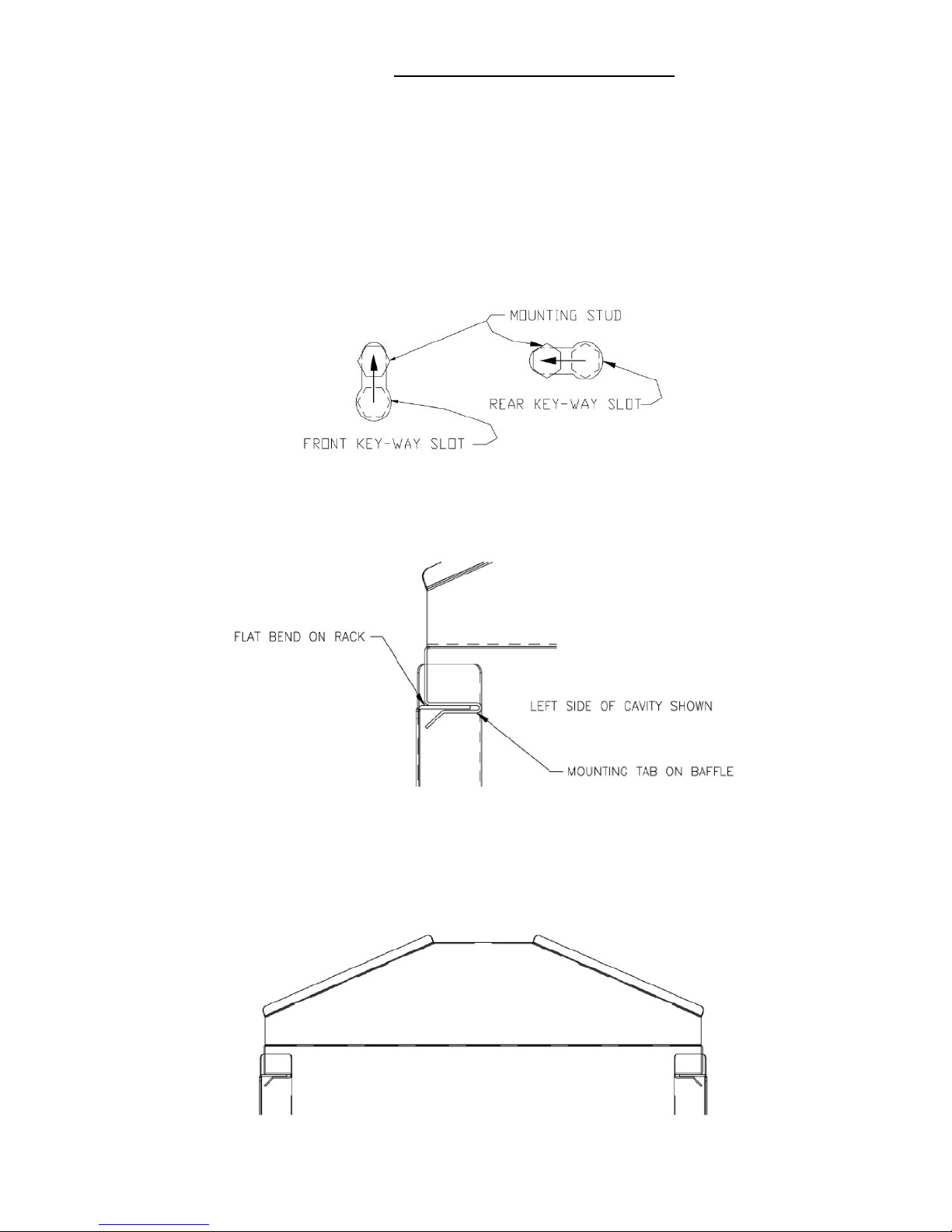
INSTRUCTIONS FOR INSTALLING PAN SUPPORTS AND BAFFLES
1. Locate the mounting studs on the inside of the chamber. There are two rack mounting studs on each side.
2. Taking one pan support and positioning rack so that the pan stop is facing the rear of the unit and the wires
are facing toward the center of the unit. The pan stop is a piece of sheet metal welded to the rack with a 65
bend.
3. Begin to hang the pan support by placing the rear key-way slot onto the rear mounting stud and slide the
rack until the slot sits on the mounting stud. When this is done correctly the front mounting stud will be in
position to place the front key-way slot. Slide the rack down into its correct position. See Fig. 1.
Fig. 1.
4. After installing one pan support rack correctly, you can install the baffle. Position the baffle so that the 45o
bend is facing up and towards the front of the unit. Slide the mounting tab onto the flat bend on the pan stop
bracket. The baffle should now stay in place by itself, but in a tilted state. See Fig. 2.
o
5. Position the second pan support rack into the cavity and slide the other mounting tab onto the rack flat bend
while the pan support rack is not on the mounting studs. Hang the pan support by placing the rear key-way
slot onto the rear mounting stud and slide the rack until the slot sits on the mounting stud. When this is done
correctly the front mounting stud will be in position to place the front key-way slot. Slide the rack down
into its correct position. See Fig. 3.
Fig. 2.
Fig. 3.
6

SECTION 1 INSTALLATION INSTRUCTIONS
THE ELECTRIC SUPPLY CONNECTIONS FOR STM-E AND STM-EL
Connect to proper electrical supply as indicated on nameplate on top of unit. Connection is
located behind the terminal box cover at the lower left side of unit. Whether the supply
current is 208 or 240 volt, single phase or three phase, all control circuits are 120 volts. In
order to accomplish this, a current-carrying grounded neutral must be provided.
Thus, a three phase system must be 4-wires and a single phase system must be 3-wires. If a currentcarrying grounded neutral is not available from the power source, a separate 120 volt circuit must be
run. Most electrical codes require, and we recommend, that a separate disconnect switch be located
within sight of the sterilizer. When a separate 120 volt control circuit must be run, this must also be
part of the disconnect box assembly.
THE ELECTRIC SUPPLY CONNECTIONS FOR STM-EX AND STM-ELX EXPORT
Connect to proper electrical supply as indicated on nameplate on top of unit. Connection is located
behind the terminal box cover at the lower left side of the unit. All control circuits are 220 volts.
In order to accomplish this, a current-carrying grounded neutral must be provided.
Thus, a three phase system must be 4-wires. Most electrical codes require, and we recommend, that
a separate switch be located within sight of the sterilizer.
7
SECTION 1 INSTALLATION INSTRUCTIONS
8
SECTION 1 INSTALLATION INSTRUCTIONS
9
 Loading...