

Page 1

OWNER’S MANUAL
ELECTRIC STERILMATIC STERILIZER
ELECTRIC STERILMATIC STERILIZER
DIGITAL VERSION
DOMESTIC MODEL: □ STM-ED
EXPORT MODEL:
INSTALLATION
•
OPERATION
•
MAINTENANCE
•
TROUBLE-SHOOTING
•
PARTS & SERVICE
•
WARRANTY
•
□ STM-EDX
FORM NO.:
03/14 REV. A
H-2117
Sterilizers.com - Your Sterilizer Expert
Telephone: (617) 387-4100, (866) 698-3188
Distribution – Maintenance - Guaranteed
Alfa Medical - 10 Bond St Great Neck NY 11021
1-800-762-1586 - info@Sterilizers.com
35 Garvey Street, Everett, MA 02149
Fax: (617) 387-4456, (800) 227-2659
custserv@m i.com, www.m i.com
Page 2

TABLE OF CONTENTS
INTRODUCTION
Product Description ..........................................................i
Service Contacts ..............................................................i
SECTION 1 INSTALLATION INSTRUCTIONS
Service & Technical Information Contact ..........................1
Operating Environmental Conditions ................................1
Intended Use - Sterilization Cycle ....................................1
Installation ........................................................................1
Electrical ...........................................................................1
Outside Venting ................................................................1
Water-Cooled Exhaust Condenser ...................................1
Tray Supports ...................................................................1
Bafe Installation ..............................................................1
Operation Check...............................................................1
Cold Water Condenser .....................................................2
Service Connections.........................................................3
Electrical Requirements....................................................3
Dimensions .......................................................................3
Instructions for Installing Pan Supports & Bafes.............4
Electrical Supply Connections ..........................................4
Wiring Diagram - 1 Phase ................................................5
Wiring Diagram - 3 Phase ................................................6
Typical Circuit Connection for STM-ED ............................7
SECTION 2 WATER CONDITIONS
Water Conditions ..............................................................9
SECTION 3 OPERATING INSTRUCTIONS
General Operating Instructions.........................................10
Load Sterilizer...................................................................10
Close Door........................................................................10
Determine Correct Sterilization Times ..............................10
Sterilization Guide ............................................................10
Minimum Sterilization Times Table ...................................11
SECTION 4 MAINTENANCE
Daily Cleaning Procedure .................................................18
SECTION 5 FIELD SERVICE INSTRUCTIONS & ASSEMBLY
Sterilmatic Open Stand.....................................................19
Sterilmatic Open Stand with Condenser...........................19
Parts List for Condenser with Optional Stand...................19
Door Adjustment ...............................................................19
Door Assembly .................................................................20
The Door Gasket ..............................................................20
Door Lift Spring.................................................................20
To Remove the Door Assembly ........................................20
The Fulcrum & Drain Assembly ........................................21
Roller Assembly ................................................................21
Cast-In Heating Elements.................................................22
Low Water Cut-Off Manual Reset .....................................22
Saftey Valve ......................................................................22
The Flue ...........................................................................22
Echaust Solenoid Valve ....................................................22
SECTION 6 ILLUSTRATED PARTS LIST
Vent Piping .......................................................................23
Electrical Components......................................................24
Sterilizer Assembly ...........................................................25
Pan Supports & Bafe ......................................................26
Door Handle Assembly .....................................................27
SECTION 7 TROUBLE-SHOOTING
Trouble Shooting Guide ....................................................29
SECTION 8 APPENDIX
Error Codes ......................................................................30
SECTION 9 WARRANTY INFORMATION
Sterilizer Warranty ............................................................31
Sterilizer Warranty Resistration ........................................32
CONTROL PANEL
Detailed Operating Instructions ........................................12
Controller Overview ..........................................................13
Set Up...............................................................................13
Manual Programing ..........................................................13
Setting Units .....................................................................13
Setting Temperature .........................................................13
Setting Time......................................................................14
Setting Vent Mode ............................................................14
Stopping the Unit ..............................................................14
Description of Cycles ........................................................14
Keys ......................................................................15
Preset
Programing Preset Keys...................................................15
Using Preset Keys ............................................................15
Printing Data Logger.........................................................15
Print Key ...........................................................................16
Printing Previously Run Cycles ........................................16
Printer Paper Cutting ........................................................16
Printer paper Changing ....................................................16
Low Water Reset ..............................................................17
Steps to Reset the Unit.....................................................17
Recommended Steps but not Required ...........................17
Page 3

INTRODUCTION
A. Product Description:
The Market Forge Sterilmatic Sterilizer with Digital Controller (model STM-ED) is a compact, automatic, low cost
steam pressure sterilizer (autoclave).
The sterilizing cylinder is a 3/16” (4.8mm) thick wall, welded aluminum. The exterior is made of polished stainless
steel. Interior dimensions of 16” (406mm) diameter and 26” (660mm) long with a cubic content of 5,220 cubic
inches (0.085 cubic meters) and has a door opening of 13-1/2” (343mm) wide and 11” (279mm) high. The steril-
izing compartment has a pan capacity of:
□ (3) 12” x 20” x 2 ½” (305mm x 508mm x 64mm) or,
□ (2) 12” x 20” x 4” (305mm x 508mm x 102mm) or,
□ (1) 12” x 20” x 6” (305mm x 508mm x 152mm)
The sterilizer door is a self-sealing type that cannot be opened until the steam pressure is completely exhausted
from the chamber. The door is 12 gauge stainless steel and removable for cleaning without tools. The door gas-
ket is one-piece molded, also replaceable without tools or cement.
The sterilizing cycle is fully automatic with the time, temperature and venting controlled by the microprocessor
based, digital controller.
The sterilizing temperature can be set anywhere in a range from 225°F (107°C) and 250°F (121°C). There is an
on-board data logger/printer. The data logger records the time, temperature and pressure for each sterilization
cycle. This data can be stored for future printing or printed out following each cycle.
B. Service Contacts:
Should repairs be required, a network of authorized agencies is available to assist with prompt service. A current
Directory of Authorized Service Agencies may be obtained by contacting:
Market Forge Industries, Inc.
Sterilizers.com - Alfa Medical - 10 Bond St Great Neck NY 11021
1-800-762-1586 - info@Sterilizers.com
To nd an Authorized Service Agent in your area, go to:
Everett, Massachusetts 02149-4403
Outside MA Fax: (800) 227-2659
Parts / Price / Service Telephone: (888) 259-7076
http://www.mi.com/company/service
35 Garvey Street
Telephone: (617) 387-4100
Toll Free: (866) 698-3188
Fax: (617) 387-4458
Email: custserv@mi.com
Web Site: www.mi.com
i
Page 4

SECTION 1 INSTALLATION INSTRUCTIONS
AUTOMATIC STERILMATIC STEAM
PRESSURE STERILIZER
MODELS: STM-ED, & STM-EDX
SERVICE & TECHNICAL INFORMATION CONTACT
NOTE: This unit should be serviced by qualied
service personnel only.
Your Sterilmatic Sterilizer has been developed to
answer the need for a compact, automatic, low-cost
steam pressure sterilizer. The following instructions
cover installation. Should service be required, it is
readily available by contacting our authorized ser-
vice agency located nearest to you. The name of
your local service company can be obtained by con-
tacting the Service Department at Market Forge.,
Tel (617) 387-4100 or e-mail custserv@mi.com, or
go to: http://www.mi.com/company/service to nd
an authorized service agent in your area.
OPERATING ENVIRONMENTAL CONDITIONS
This unit is designed for commercial use and to be
safe at least under the following conditions:
For indoor use only.
•
For use at altitudes up to 6500ft (2000m)
•
For use at temperatures from 41
•
o
F (5oC) to 104oF
(40oC).
Maximum relative humidity 80% for temperatures
•
up to 88oF (31oC) decreasing linearly to 50% rela-
tive humidity at 104
Main supply voltage uctuations not to exceed ±
•
o
F (40oC).
10% of nominal voltage.
Transient overvoltages according to Installation
•
Categories II (in accordance with IEC 664).
Pollution Degree 2 (in accordance with IEC 664).
•
INTENDED USE - STERILIZATION CYCLE
This unit is intended to be operated intermittently.
After a pre-heat cycle, the longest period of sterilization (heating) should be a maximum of 60 min-
utes. The digital timer allows up to 99 minutes, but
it should be kept at no more than 60 minutes. After
each use the unit should be opened for removal
and reloading of product. The water level should
be checked after each use and relled when nec-
essary.
INSTALLATION
Set sterilizer on counter, using the 6” (152mm) legs
provided or assemble the optional stainless steel stand
with under-shelf. If your Sterilmatic includes a watercooled exhaust condenser, we recommend the use
of the Sterilmatic stand, part number 95-6060. First,
level unit in place, then adjust rear legs to pitch the unit
forward 1/4” (6mm) to insure positive drainage of the
cylinder.
ELECTRICAL
Connect to proper electrical supply box and disconnect
switch as shown on one of the following schematic diagrams - 208 or 240 volts, single or three phase. Con-
nection is made from the rear of the unit, through the
conduit to the terminal box located at the front of the
unit. See installation specications on page 5.
OUTSIDE VENTING
Connect 1/2” (13mm) nominal tubing exhaust to out-
side vent connection located on top of unit, within the
control housing. IMPORTANT: Exhaust line must be
vented to the outside to eliminate the exhausted steam
and the accompanying noise from entering the room.
Use 1/2” (13mm) copper tubing or suitable alternate.
The overall height and length of the line should not rise
more then 4 feet (1.2 meters) above the unit and exceed 15 feet (4.5 meters) with a minimum of bends.
The line should slope downward after leaving the steril-
izer in order to insure condensate drainage.
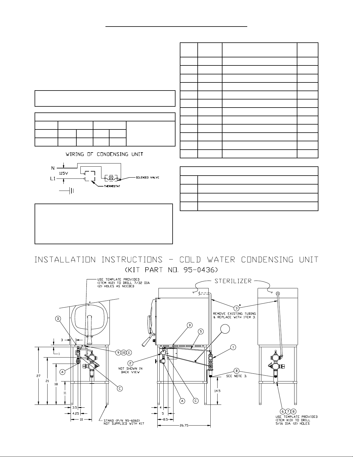
WATER-COOLED EXHAUST CONDENSER
If outside venting is not possible, an optional watercooled condenser is available for connection to an
open drain. If required order part no. 95-0436 kit.
TRAY SUPPORTS
Install side tray supports. Tray supports are attached
by means of key-hole clearance slots which are slipped
over studs located on the sides of the Sterilmatic cham-
ber.
BAFFLE INSTALLATION
To insure maximum drying of packs, a bafe is supplied
with your Sterilmatic. Place perforated splash bafe in
bottom of the sterilizing chamber. Install small bafe
with no perforation at the rear of the upper tray support
channel.
NOTE: The perforated bafe is not to be used as a
shelf to place media or other items. It is intended to
eliminate splashing.
OPERATION CHECK
To check for proper operation of unit:
Close drain valve by turning handle clockwise.
1.
WARNING: DO NOT OPEN DRAIN VALVE WHILE
UNIT IS OPERATING. PREMATURE OPENING
MAY RESULT IN SCALDING OF OPERATOR.
Fill chamber with 4 to 5 quarts (3.8 to 4.7 liters) of
2.
ordinary tap water. DO NOT USE DISTILLED OR
1
Page 5
SECTION 1 INSTALLATION INSTRUCTIONS
DEIONIZED WATER.
Close chamber door.
3.
Set exhaust selector to INSTRUMENTS AND
4.
PACKS (fast exhaust) or LIQUIDS (slow exhaust).
Set timer to 15 minutes. Cycle will go to completion
5.
automatically.
NOTE: Sterilizing cycle timer will not start until steril-
izing set point temperature is obtained.
AMPS PER WIRE *STERILIZER
Phase 3 Phase 1 Phase
Volts 208 240 208 240
Amps 26 30 45 52
208V
240V
(197-219)
or
(220-240)
NOTES:
Unit must be grounded and all wiring to comply with local
1.
codes.
Pipe to open drain. Do not make solid connection to sewer.
2.
Condensing unit to bt installed. Requires a front to back pitch,
3.
shown in the illustration below (see A).
COLD WATER CONDENSER
PART
ITEM
1 95-2119 Steam condensing unit 1
2 95-2219 Thermostat
3 95-0086 Exhaust line 1
5 15-7057 Copper tubing 3/8
6 10-1775 Rd. Hd. Mach. Screw, 1/4-20 2
7 10-2500 Lockwasher, 1/4 2
8 10-2308 Hex Nut, 1/4-20 2
9 10-1812 Rd. Hd. Mach. Screw, 10-32 2
10 10-2505 Lockwasher, 10 2
11 10-2340 Hex Nut, 10-32 2
12 95-4009 Front
13 95-4010 Back Template (11” Lg) 1
A
B
C
D
NO. DESCRIPTION
Box Assy. 1
OD
Template (7” Lg) 1
SERVICE CONNECTIONS REQUIRED
1/2” IPS Cold Water Connection
1” IPS Drain Connection (See Note 3)
115V Elec. Connection 7/8 Ø knockout (cond. unit)
Electrical Connection
QTY.
22.25”
A
2
Page 6
SECTION 1 INSTALLATION INSTRUCTIONS
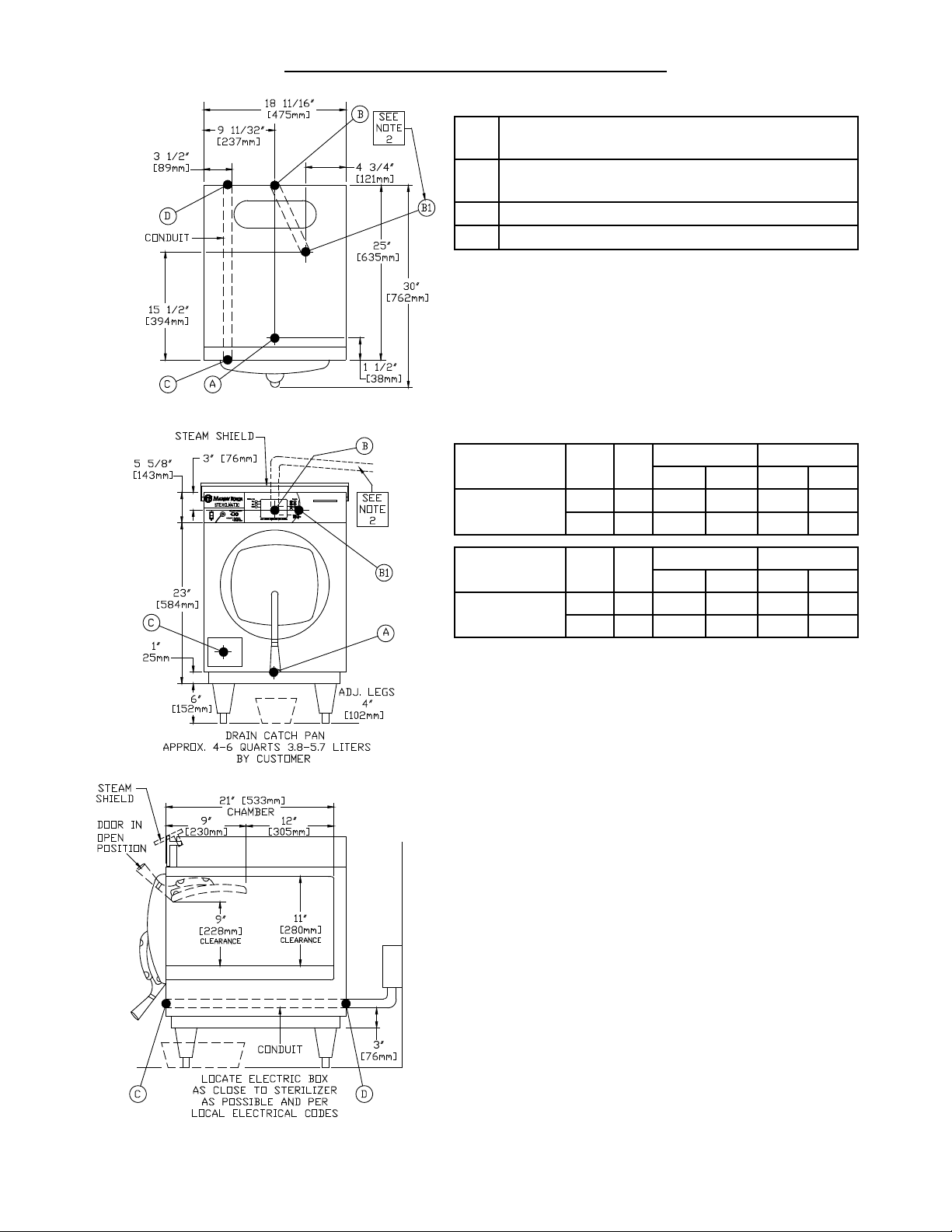
REQUIRED CONNECTIONS:
A Drain - 1/2” (13mm) FPT of 5/8” (16mm) OD
copper (see note 1)
B Steam Exhaust Connection - 3/8” (10mm) IPS
(see note 2)
C Electrical Connection - (*see table below)
D Power Supply
ELECTRICAL REQUIREMENTS: Unit will be rated at
12kW at 236V and will be equipped for operation at:
□ 208-240V, 3 Wire, 1 Phase, 60 Hz
□ 208-240V, 4 Wire, 3 Phase, 60 Hz
□ 220V, 1 Phase, 50 Hz
□ 220V, 3 Phase, 50 Hz
AMP/PHASE
DOMESTIC
MODEL
STM-ED
kW Hz
9.3 60 45A - 26A -
12.4 60 - 52A - 30A
Single Phase
208V 240V 208V 240V
Three Phase
EXPORT
MODEL
STM-EDX
•
UNIT MUST BE GROUNDED
•
MAIN SUPPLY VOLTAGE FLUCTUATIONS ARE NOT TO
EXCEED ± 10% NOMINAL SUPPLY VOLTAGE
kW Hz
10.4 50 48A - 16A -
12.4 50 - 52A - 18A
Single Phase
220V 240V
Three Phase
220/380V 240/415V
NOTES:
An air break must be provided if a unit drain line is run.
1.
Vent exhaust to atmosphere. B1 is actual connection,
2.
but must exit casing at B.
IMPORTANT: Exhaust line must be vented to the outside to eliminate the exhaust steam and the accompanying noise from entering the room. Use 1/2” (13mm)
copper tubing or suitable alternate. The overall height
and length of the line should not rise more then 4’ (1.2
meters) above the unit and exceed 15’ (4.5 meters) with
a minimum of bends. The line should slope downward
after leaving the sterilizer in order to ensure condensate
drainage.
IMPORTANT: Failure to comply with this outline will af-
fect the sterilization process.
When an exhaust condenser is supplied; the following
services must be provided: 1/2” (13mm) IPS cold water:
1” (25mm) IPS waste: 115V electrical line.
3
Page 7

SECTION 1 INSTALLATION INSTRUCTIONS
INSTRUCTIONS FOR INSTALLING PAN SUPPORTS AND BAFFLES
Locate the mounting studs on the inside of the chamber. There are two rack mounting studs on each side
1.
(see Fig. 1).
Taking one pan support and positioning rack so that the pan stop is facing the rear of the unit and the wires
2.
are facing toward the center of the unit. The pan stop is a piece of sheet metal welded to the rack with a 65° bend.
Begin to hang the pan support by placing the rear key-way slot onto the rear mounting stud and slide the rack
3.
until the slot sits on the mounting stud. When this is done correctly the front mounting stud will be in position
to place the front key-way slot. Slide the rack down into its correct position (see Fig 2).
After installing one pan support rack correctly, you can install the upper bafe. Position the bafe so that the
4.
45° bend is facing up towards the front of the unit (see Fig. 3). Slide the mounting tab onto the at bend on
the pan stop bracket. The bafe should now stay in place by itself, but in a tilted state (see Fig. 4).
Position the second pan support rack into the cavity and slide the other mounting tab onto the rack at bend
5.
while the pan support rack is not on the mounting studs. Hang the pan support by placing the rear key-way
slot onto the rear mounting stud and slide the rack until the slot sits on the mounting stud. When this is done
correctly the front mounting stud will be in position to place the front key-way slot. Slide the rack down into
its correct position.
Place the Perforated Water Bafe so that it sits on the bottom of the inside of the sterilizer chamber (see Fig. 5).
6.
CAUTION: Do not cover the holes in the Perforated Water Bafe by using it as a shelf. This will result in a
7.
disrupted ow of steam.
THE ELECTRIC SUPPLY CONNECTIONS FOR STM-ED: Connect to proper electrical supply as indicated on
nameplate on top of unit. The power supply cord is brought in from the rear of the unit, through the conduit and
the connection is made at the terminal box located at the front of the unit.
THE ELECTRIC SUPPLY CONNECTIONS FOR STM-EDX: Connect to proper electrical supply as indicated on
nameplate on top of unit. Connection is made from the rear of the unit, through the conduit to the terminal box
located at the front of the unit. All control circuits are 220 volts.
In order to accomplish this, a current-carrying grounded neutral must be provided.
Thus, a three phase system must be 4-wires. Most electrical codes require, and we recommend, that a separate
switch be located within sight of the sterilizer.
4
Page 8
SECTION 1 INSTALLATION INSTRUCTIONS
SSR
3+
-
1
CONTROL
BOARD
2
1
2
1
2
4
9
8
3
7
2
1
P4
P13
PRINTER
1
2
J4
POWER
J3
J21
J21
J21
J21
J21
J5
J14
J1
J13
T1
POWER
LOW WATER LED
P21
P5
T1
THERMISTOR
PROBE
EXHAUST
VALVE
4
2
1
+
-
L
G
POWER
SUPPLY
5 VDC
K1
2
3
5
4
24
7
8
9
6
26
23
K3
LOW WATER
CUTTOFF
13
13
13
13
27
L1
L2
L1
L2
L1
L2
POWER
31
29
1.5 A
FUSE
1
5
20
N
28
22
L2 (2A)
L1 (1A)
L1
L2
L3
T2
T3
23
16
14
21
25
RS232
RS232
13
18
15
4
MK
22
HEATER 2
17
HEATER 1
T1
T2
K2 T1
T2
19
HEATER 3
T1
T2
25
11
10
12
WIRE YEL 22 GA
WIRE BRN 22 GA
WIRE RED 22 GA
WIRE RED 22 GA
WIRE RED 22 GA
WIRE BLU 18 GA
WIRE BLU 22 GA
WIRE RED 18 GA
WIRE BLK 22 GA
WIRE ORG 22 GA
WIRE ORG 22 GA
WIRE ORG 18 GA
WIRE ORG 22 GA
WIRE ORG 18 GA
WIRE RED 18 GA
WIRE BLK 18 GA
WIRE ORG 18 GA
WIRE RED 18 GA
30
WIRE BLU 18 GA
WIRE ORG 22 GA
WIRE ORG 22 GA
WIRE BLK 16 GA
WIRE RED 16 GA
WIRE WHT 16 GA
WIRE RED 16 GA
WIRE WHT 16 GA
WIRE BLK 16 GA
WIRE RED 18 GA
WIRE ORG 22 GA
WIRE ORG 22 GA
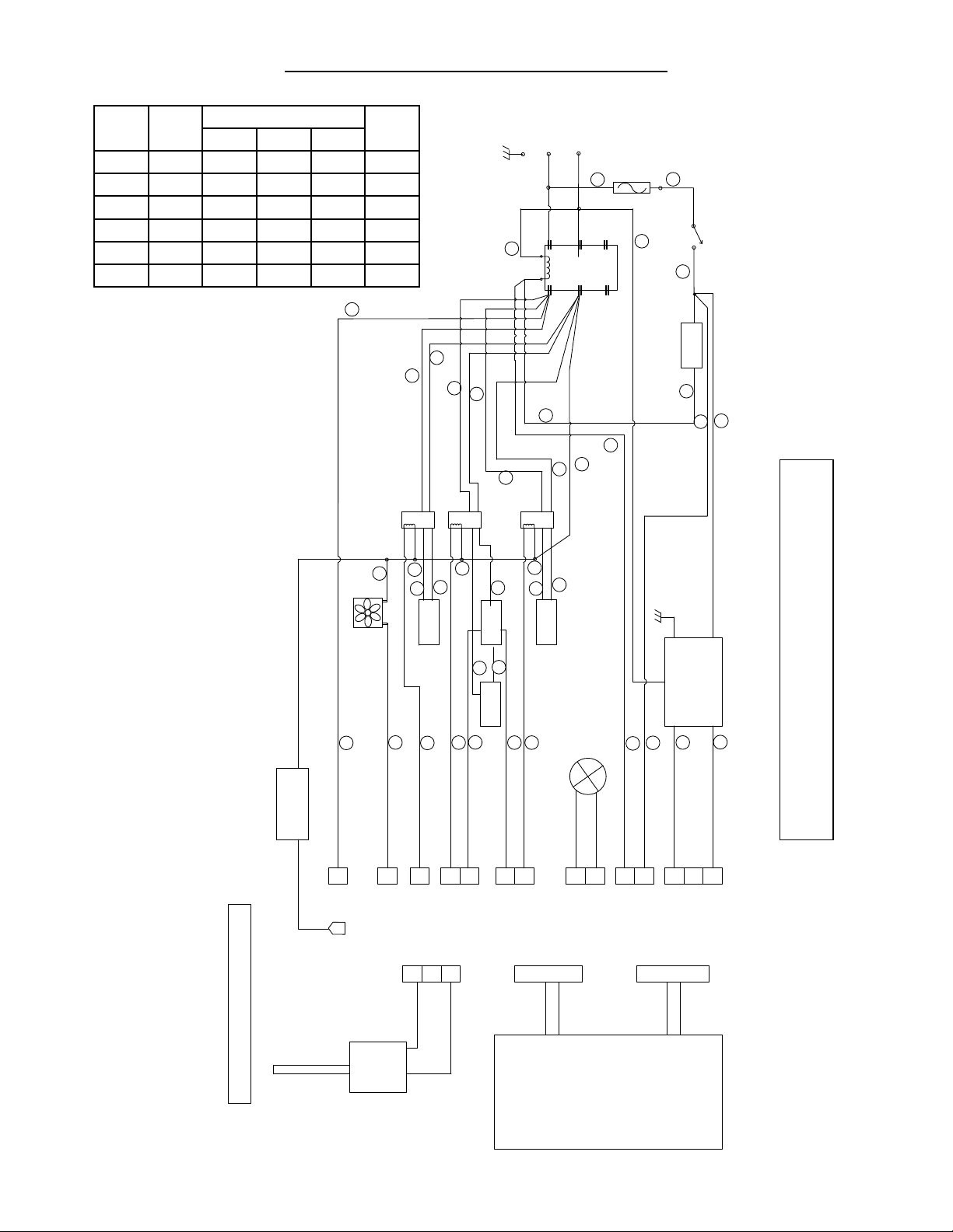
DIGITAL STERILMATIC MODEL STM-ED - 1 PHASE WIRING DIAGRAM
DRAWING No. 95-6311 Revision A - Date 10/25/13
DRAWING No. 95-6311 Revision A
Volts Phase
AMPs Per Line Wire
L1 L2 L3
kW
208 1 45 45 -- 9.3
208 3 26 26 26 9.3
220 1 48 48 -- 10.4
220 3 28 28 28 10.4
240 1 52 52 -- 12.4
240 3 30 30 30 12.4
5
Page 9
SECTION 1 INSTALLATION INSTRUCTIONS
SSR
3+
-
1
CONTROL
BOARD
2
1
2
1
2
4
9
8
3
7
2
1
P4
P13
PRINTER
1
2
J4
POWER
J3
J21
J21
J21
J21
J21
J5
J14
J1
J13
C
C
T1
POWER
LOW WATER LED
P21
P5
T1
THERMISTOR
PROBE
EXHAUST
VALVE
4
2
1
+
-
L
G
POWER
SUPPLY
5 VDC
K1
2
3
5
4
24
7
8
9
6
26
23
LOW WATER
CUTTOFF
13
13
13
13
27
L1
L2
L1
L2
POWER
31
29
2.0 A
FUSE
1
5
20
N
1
22
L3 (3A)
L2 (2A)
L1 (1A)
30
L1L2L3
T2
T3
23
16
14
21
25
RS232
RS232
13
18
15
4
MK
22
WIRE RED 18 GA
WIRE BLK 22 GA
WIRE ORG 22 GA
WIRE YEL 22 GA
WIRE BRN 22 GA
WIRE RED 22 GA
WIRE RED 22 GA
WIRE ORG 22 GA
WIRE ORG 22 GA
WIRE BLK 16 GA
WIRE ORG 18 GA
WIRE ORG 22 GA
WIRE RED 22 GA
WIRE BLU 18 GA
WIRE BLU 22 GA
WIRE RED 16 GA
WIRE WHT 16 GA
WIRE RED 16 GA
WIRE BLK 16 GA
WIRE ORG 18 GA
WIRE BLU 18 GA
WIRE ORG 22 GA
WIRE RED 18 GA
WIRE ORG 18 GA
WIRE BLK 18 GA
WIRE RED 18 GA
WIRE WHT 16 GA
WIRE ORG 18 GA
WIRE RED 18 GA
WIRE ORG 22 GA
FAN
K3
L1
L2
HEATER 1
T1
T2
K2
T1
T2
HEATER 3
T1
T2
25
11
10
12
HEATER 2
17
19
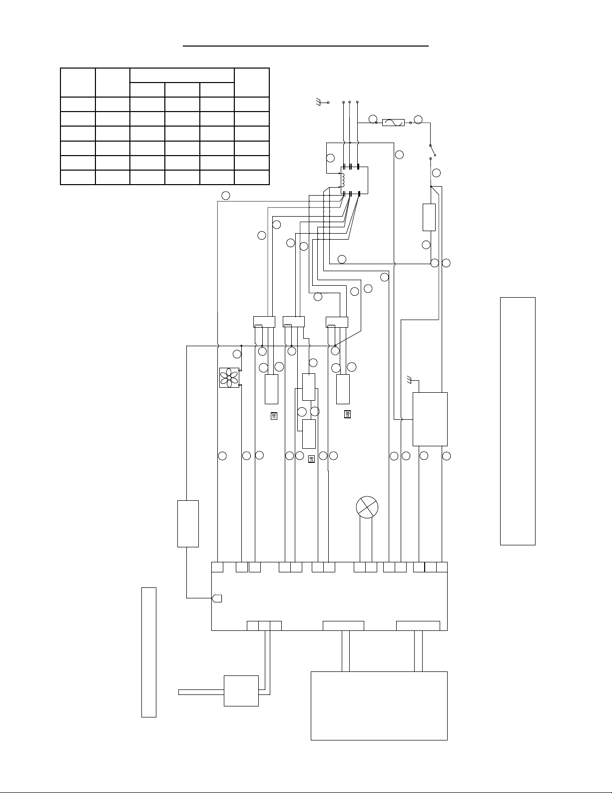
DIGITAL STERILMATIC MODEL STM-ED - 3 PHASE WIRING DIAGRAM
DRAWING No. 95-6312 Revision A - Date 10/25/13
DRAWING No. 95-6312 Revision A
Volts Phase
AMPs Per Line Wire
L1 L2 L3
kW
208 1 45 45 -- 9.3
208 3 26 26 26 9.3
220 1 48 48 -- 10.4
220 3 28 28 28 10.4
240 1 52 52 -- 12.4
240 3 30 30 30 12.4
6
Page 10

SECTION 1 INSTALLATION INSTRUCTIONS
15
240 Volt, 3 Phase
240
240
16
23
13
25
14
18
21
40A
40A
40A
L
1
L2
L3
ELECTRICAL SOURCE UNIT WIRING
FUSE AND
DISCONNECTED MEANS
TYPICAL CIRCUIT CONNECTION FOR STM-ED STERILIZER
240
15
208 Volt, 3 Phase
208
208
16
23
13
25
14
18
21
40A
40A
40A
L
1
L2
L3
208
15
240 Volt, 1 Phase
240
21
16
23
18
25
14
13
60A
60A
L
1
L2
15
208 Volt, 1 Phase
208
21
16
23
18
25
14
13
50A
50A
L
1
L2
7
Page 11

SECTION 1 INSTALLATION INSTRUCTIONS
1
4- Wire, 3 Phase
Delta (480/240V)
4- Wire, Wye Connected
380/220V, 3 Phase
240
240
8
2
12
19
25
7
5
20A
20A
20A
L
2
L1
N
N
L
3
480
ELECTRICAL SOURCE UNIT WIRING
FUSE AND
DISCONNECTED MEANS
TYPICAL CIRCUIT CONNECTION FOR STM-EDX STERILIZER -EXPORT-
480
415
415
20A
20A
20A
L
1
L2
L3
240
1
8
2
12
19
25
7
5
4- Wire, Wye Connected
415/240V, 3 Phase
N
380
380
20A
20A
20A
L
1
L2
L3
220
1
8
2
12
19
25
7
5
This page intentionally left blank.
8
Page 12

SECTION 2 WATER CONDITIONS
Market Forge from time to time is asked the question about using distilled or deionized water for use with our
Sterilizer models STM-ED and STM-EDX. We are always asked why these water choices are not allowed for use
with our units and what would be recommended. To address this situation, we have complied the following as a
means of satisfying these questions:
We have found that the use of distilled or deionized water will aggressively attack the pure coat of Aluminum
1.
Alclad, which protects the bottom surface from oxidizing and then eventually pitting (reference: Operating
and Maintenance Instructions).
In addition pitting can also be caused by several other external environmental factors. Few examples are as
2.
follows. These conditions have been highlighted in our documentation.
Grains of hardness in the water supply should be as follows (.25 to 2).
•
A pH imbalance in the water supply can greatly affect the life to the aluminum cylinder. The pH range that
•
would be recommended is between 7.0-8.5.
The lack of a positive electrical ground can cause an electrolytic reaction that will accelerate pitting.
•
Another contribution to accelerate pitting is the type of cleaning solutions used or the abrasive scrubbing
•
pads. If a low pH is present with the detergents being used or an abrasive pad, the protective Alclad coating
will be removed during the cleaning process.
Spillage of media being sterilized can also contribute to the accelerated pitting if it is corrosive.
•
CHLORINE LEVEL ≤ 1 PPM.
•
IMPORTANT NOTE:
Market Forge will not be responsible for damage resulting from the use of hard or corrosive water, from
failure to drain the unit daily, or from inadequate cleaning procedures.
9
Page 13

SECTION 3 OPERATING INSTRUCTIONS
GENERAL OPERATING INSTRUCTIONS:
IMPORTANT: Make sure the drain valve is closed.
1.
Fill bottom of the sterilizer chamber with approxi-
mately six quarts of water or just below ledge at
bottom of door opening. (If water supply is known
to be hard or corrosive, a source of treated water
should be used.) DO NOT USE DISTILLED OR
DEIONIZED WATER. (See section 2)
LOAD STERILIZER: Use proper sterilizer load-
2.
ing procedures when placing materials in sterilizer
chamber. All solid containers or instruments must
be placed so that water or air will not be trapped
in them.
CLOSE DOOR: Grasp handle, and holding it
3.
in vertical position, pull door down until bottom of
door rests in the bottom of door opening. Then
rotate handle forward, engaging the lower curved
portion under the horizontal rod in the casting at
the bottom of the door opening. Push handle all the
way down and back until door is locked securely in
position.
DETERMINE CORRECT STERILIZATION
4.
TIMES: (Referring to page 11 for minimum steril-
ization times table.) NOTE: In no case should the
timer be set to less than 15 minutes. Sterilization
will not be accomplished in less than 15 minutes
exposure time.
When the sterilizer chamber reaches the selected
5.
temperature, the timed Heating/Sterilization cycle
will begin. When the Heating/Sterilization cycle
is completed, the electric supply to the heating
elements will be opened (shut off) automatically.
When the chamber pressure reaches 0 (zero) the
door may be opened.
NOTE: Before opening the chamber door be
sure to have the Control Panel Flip Cover in the
‘DOWN’ position. This protects the LCD screen
from coming into contact with too much steam.
position. This will allow steam and moisture to es-
cape. Allow door to remain in this position for 15
to 20 minutes before removing load. Small packs
can be dried successfully with this procedure. We
do not recommend the sterilization of large packs,
such as linens. Be sure condensate bafes are in
position in the chamber.
Remove load and check water level for next opera-
7.
tion.
STERILIZATION GUIDE:
PACKS (Linens, gloves, etc.): Use wire basket
•
to facilitate drying. Be sure condensate bafes are
in place. Place packs on edge and arrange load in
chamber, so that only minimal resistant to passage
of steam through the load will exist.
NOTE: Place gloves in upper two-thirds of chamber.
•
JARS, CANISTERS (etc.): Place containers on
side to allow for displacement of air and complete
contact of steam to surfaces. Drying is also facili-
tated.
PETRI DISHES, PIPETTES, DESICCATORS
•
(etc.): Should be inverted.
UTENSILS, TREATMENT TRAYS: Placed on
•
edges to facilitate drying.
INSTRUMENT SETS: Place instruments set in
•
trays having mesh or perforated bottoms. Place
trays at on shelves.
COMBINING FABRICS & HARD GOODS:
•
Place hard goods on lowest shelves.
PLASTIC UTENSILS: DO NOT stack or nest
•
plastic items.
LIQUIDS: Sterilize liquids separately from other
•
supplies or materials. Set vent to slow.
SMALL ITEMS: Sterilize small items in baskets,
•
or trays.
At this point you may release the handle and let
go to avoid possible contact with the remaining
escaping steam. When opening the door allow a
few seconds for steam to escape from the cham-
ber before opening completely.
NOTE: For more detailed Operating Instructions
please refer to Section 3 titled ‘DETAILED OPERATING INSTRUCTIONS’
6.
To assist in drying racks, release door handle af-
ter pressure has been attained at start of cycle.
Pressure in chamber will keep door closed. The
use of a wire basket will provide better drying for
dressings. At end of sterilizing cycle, release door
handle and open slightly. Do not lift door to open
NOTE: IF THE EQUIPMENT IS USED IN A MAN-
NER NOT SPECIFIED BY THE MANUFACTURER,
THE PROTECTION PROVIDED BY THE EQUIPMENT MAY BE IMPAIRED.
10
Page 14

SECTION 3 OPERATING INSTRUCTIONS
TIME (Minutes) ARTICLES
15 Glassware, empty, inverted.
•
Instruments, metal in covered or open tray, padded or unpadded.
•
Needles, unwrapped.
•
Pipettes, blood diluting, serological, volumetric, etc
•
Tubing glass (6mm), (10mm) inverted
•
MINIMUM STERILIZATION TIMES
20 Flasked solutions 75-250 ml.
30 Brushes in dispensers, in cans of individually wrapped.
45 Flasked solutions 1500-2000 ml.•
•
Instruments, metal combined with other materials in covered and/or padded tray.
•
Instruments wrapped in double thickness muslin.
•
Rubber gloves, catheters, drains, tubing, etc. Unwrapped or wrapped in muslin or
•
paper.
•
Dressings, wrapped in paper or muslin, small packs only.
•
Flasked solutions 500-1000 ml.
•
Syringes, unassembled, individually packaged in muslin or paper.
•
Needles, luer, individually packaged in glass tubes or paper.
•
11
Page 15

SECTION 3 OPERATING INSTRUCTIONS
DETAILED OPERATING INSTRUCTIONS
Before operating this unit be sure to have read the Owner’s manual for proper setup, service connections and
installation. In addition, the Owner’s manual will cover sterilization recommendations, daily cleaning procedures
and parts lists.
A. ControlPanelIdentication
2 11
10 9 7 8 13
1 3 12 4 5 6
IITEM DESCRIPTION BUTTON
1 Control Panel Power - ON ( I ), OFF ( 0 )
2 Reset Button
3 Low Water Indicator Light
14
4 Down Key
5 Printer Key
6 Preset Keys
7 Up Key
8 Start / Cancel Key
9 Digital LCD Display
10 Temperature Key
11 Time Key
12 Vent Key
13 Print out
14 Printer Door Button
12
Page 16

SECTION 3 OPERATING INSTRUCTIONS
B. Controller Overview
The Digital Controller is made up of the Operational Keys, Digital LCD Display and the Data Logger/Printer. The
operator can set the controller to display in either degrees Fahrenheit (°F) with pressure in PSI or in degrees
Celcius (°C ) with pressure in kPa.
During operation the Digital LCD Display will show the actual temperature within the sterilizer chamber, the time
remaining for the sterilizer cycle and the vessel pressure in digital form and bar form. It will also display the current cycle state, Heating up, Timing (sterilizing) or Venting.
The three operating parameters that can be set by the operator are sterilizing Temperature, sterilizing Time
and Venting mode.
The sterilizing temperature can be set in a range from 225°F (107°C) to 250°F (121°C).
The sterilizing Time can be set in Minutes and Seconds (if desired).
The Venting mode can be set to FAST (approximately 3 minutes) or SLOW (approximately 11 minutes).
To initiate a sterilizing cycle you need to set three parameters, Temp, Time and Venting. Or you can set com-
monly used values for these parameters into three ‘Preset’ keys. Each Preset key can store a value for all three
parameters. The parameter values stored in the Preset keys can easily be selected before running a sterilization
cycle. This avoids you having to set all three parameters every time you run the unit.
Each sterilization cycle records the temperature, time and pressure at one minute intervals during the heat-up
cycle, the sterilization cycle and the venting cycle. These cycles are described in more detail below. The re-
corded data can be printed out after each complete run or printed out later, on an as-needed basis.
C. Setup
Make sure unit is connected to its electrical source. Make sure unit has recommended amount of water in its
chamber. Make sure unit drain is closed. If a ventilation hood is required, make sure unit is placed accordingly
under the hood.
Be sure that the unit’s door is closed and locked before operating!
Once the unit has power, push the black Control Panel Power switch to On ( I ). This will bring power to the
control panel and illuminate the Digital LCD Display screen.
You are now ready to use the unit.
D. Manual Programming
The rst step is to decide what form of temperature and pressure measurement you want to use, Fahrenheit and
PSI or Celsius and kPa. This can be changed at any point during operation.
Setting units (°F & PSI) or (°C & kPa);
●
Press and hold the UP key and the DOWN key while simultaneously pressing and releasing the TEMP
▪
key will toggle between (°F/PSI) and (°C/kPa).
Setting Temperature
●
While the unit is powered up but not in use, considered the ‘Idle State’, the temperature being displayed
▪
is the current temperature within the sterilizer chamber.
Pressing and releasing the TEMP key will display the current set-point temperature for three seconds.
▪
To set the target sterilization temperature set-point;
▪
13
Page 17

▫
▫
Setting Time
●
While in the ‘Idle State’ the Time being displayed is the current time set-point.
▪
To set the target sterilization time set-point;
▪
▫
▫
▫
Setting VENT mode
●
While in the ‘Idle State’ the VENT mode will be displayed as either FAST or SLOW, whichever is active.
▪
To set the desired VENT mode (SLOW or FAST);
▪
▫
SECTION 3 OPERATING INSTRUCTIONS
Press and hold the TEMP key until the display goes blank and shows only the temperature. Now
press the appropriate UP or DOWN key to get to desired set-point.
When the full display returns the target set-point has been set.
Press and hold the TIME key until the display goes blank except for the minutes. Now press the
appropriate UP or DOWN key to reach the desired sterilization set-time minutes.
After three seconds the minutes will blank and the seconds set-point will be displayed. If you
need to set the desired seconds, again, use the appropriate UP or DOWN keys.
If seconds are not required than either don’t touch any key and after three seconds the full dis-
play will come back and the TIME is now set or immediately press the TIME key again and that
will also set the time.
At any point during any cycle the VENT mode can be toggled simply by pressing and releasing
the VENT key.
Starting the unit
●
Once you have set your desired TEMP, TIME and VENT type you can now proceed in starting the unit.
▪
To start unit;
▪
Press the START/CANCEL key
▫
Stopping the unit
●
Once the unit is started it will run through all 3 cycles automatically (cycles are described below) and fin-
▪
ish in the DONE state (also described below).
If at any time throughout the cycle you have to stop or cancel the cycle just press and hold (for 3 seconds)
▪
the START/CANCEL key.
After stopping the unit in this manner the unit will still have to go through the VENT cycle to release the
▪
pressure within the chamber before you can open the unit door.
Description of cycles;
●
HEATING cycle – Once the START/CANCEL key is pressed the unit will flash the HEATING icon while
▪
the sterilizer is heating up to the sterilization temperature set-point. While it is heating the set-point TIME
is displayed and will not change.
TIMING (sterilizing) cycle – When the unit reaches its set-point temperature the unit will enter the steril-
▪
ization or TIMING cycle. At this point the unit will display and count down the sterilization time.
VENTING cycle – When the timing (sterilization) cycle time reaches zero the set VENTING cycle begins.
▪
The FAST VENT is programmed to vent for 3 minutes through the solenoid valve. The SLOW VENT is
programmed to vent for 11 minutes through a bleeder orifice.
DONE state – At the completion of the VENTING cycle the unit will display DONE and a beeper will
▪
sound. The beeper sequence will be ON for 1 second and OFF for 9 seconds. This sequence will repeat
until any key on the control panel is pressed or 3 minutes have passed.
Once in the DONE state it is safe to open the chamber door. Before opening the chamber door be sure
to have the Control Panel Flip Cover in the ‘Down’ position. This protects the LCD screen from coming
into contact with too much escaping steam from the chamber. When the door is left in the closed position
you may notice a rise in the temperature and pressure on the LCD screen. You should open the chamber
14
Page 18

SECTION 3 OPERATING INSTRUCTIONS
door to allow the chamber to cool.
NOTE: There is never any harm in releasing the chamber door latch. If there is pressure inside the chamber the door cannot open due to its design which does not allow the door to open under pressure.
E. Preset Keys
There are three PRESET keys numbered 1, 2 & 3. In each key you can save set-point values for the Tempera-
ture, Time and Vent mode. For example, if you commonly need to sterilize a media that requires specic set-
point values, you can save these specic values into a PRESET key. This way you don’t need to keep setting
the Temp, Time and Venting info before each running of a sterilization cycle.
Programming PRESET Keys
●
To save values into a PRESET key;
▪
Press and hold the desired PRESET key (1, 2 or 3). The display
▫
shows the values currently stored in that preset key. When the
“PRESET” icon and the preset “number” icon in the display start to
flash, the values are now ready to re-program. At this point you can
change any or all of the parameters, Temp, Time, Vent as described
previously.
Every three seconds without an UP or DOWN key press the display
▫
will proceed from TEMP, MINUTES, then to SECONDS waiting for
new preset set-points then exits the program preset state.
During this programming state you can advance from the Temp
▫
menu to the Time menu simply by pressing the TIME key.
Likewise, while in the Time menu you can advance from Time-min-
▫
utes to Time-seconds simply by pressing the TIME key.
In addition, while in the Time menu you can go back to the Temp
▫
menu by pressing the TEMP key.
At any point during this programming state you can press the appro-
▫
priate PRESET number key and that will store the new values and
exit the programming state.
Using PRESET Keys
●
While the unit is in the ‘Idle State’ simply press the appropriate PRESET key
▪
(1, 2 or 3) to use the values previously stored into that PRESET key. At this
point you just need to press the START/CANCEL key.
F. Printing/Data Logger
This unit is set up to record the Time, Temperature and Pressure during all phases of
the full sterilization cycle. All three of these parameters are recorded at one-minute
intervals. The data logging clearly labels the printed output with headers separating
the three cycles, HEATING, STERILIZING and VENTING.
Each run is assigned a unique ID number that is printed at the top of the printout.
Each unique ID number is made up of two numbers separated by a dash (-).
(Example; #237-00053)
PRINT OUT EXAMPLE
The rst 3 digit number is a number that never changes. It is a unique number that identies the sterilizer unit
itself. The last ve digits are incremented by one for every time the unit is run.
15
Page 19

SECTION 3 OPERATING INSTRUCTIONS
Also included at the end of each printout is the following; Example:
The DATE, OPERATOR and COMMENTS elds can be hand written in if
required.
PRINT Key
●
In the LCD Display, if the word PRINT is displayed then the recorded data will be automatically printed
▪
at the end of the full sterilization cycle. Likewise, if the word PRINT is not displayed then the recorded
data will not be printed automatically after the full sterilization cycle completes.
To toggle between PRINT enable and PRINT disable just press and release the PRINT key. This can
▪
be performed at any time during the Heating, Timing (Sterilization) or Venting cycles.
Printing previously run cycles
●
The data logger will store approximately 20 full sterilization cycles. This number may vary slightly de-
▪
pending on how long each cycle runs. For example, the data logger can store more cycles set at 30
minutes versus cycles all set at 60 minutes.
As stated before each full cycle is assigned a unique ID number. This number can be used to scroll
▪
back through the data logger and print out the exact cycle you want to print out. There is also an option
to print out ALL the previous cycles.
To print out selected cycles;
▪
Press and hold the PRINT key. The display will show the ID of the last run cycle. To scroll back
▫
through the cycles just press the DOWN key. Likewise, during the scrolling, you can hit the
UP key to scroll forward through the cycles. At your selected cycle ID number just press and
release the PRINT key.
To print out all the cycles;
▪
Press and hold the PRINT key. When the display shows the last run ID number keep hitting the
▫
DOWN key until the word ‘ALL’ is displayed. Now press and release the PRINT key.
▫
Printer Paper cutting
●
The paper will be cut automatically at the end of each single print or printing ALL.
▪
DATE:
OPERATOR:
COMMENTS:
G. Printer Paper Changing
Follow these steps to re-load the printing paper;
Push the printer door “open” button. Two doors will open, the inner door and outer door.
1.
Remove paper roll spool from printer. Remove black plastic spindle from center of spent paper roll. DO
2.
NOT DISCARD BLACK PLASTIC SPINDLE!
Insert black plastic spindle into new paper roll. Insert new paper roll into printer. (Note: paper exits
3.
from top of roll)
Hold paper tip with one hand and close the inner door by pressing on the yellow strip.
4.
Close black outer door making sure that paper protrudes through the slot.
5.
16
Page 20

SECTION 3 OPERATING INSTRUCTIONS
H. Low Water Reset
If the water inside the chamber is allowed to run dry it will trigger the Low Water Cut-off. At this point the unit
will;
Shut down all three heating elements
▫
Light the red Low Water indicator light.
▫
Start the Venting cycle
▫
The Data Logger will record the error code
▫
(Note: The sterilizer’s LCD display may show the temperature and pressure rising slightly during this venting
period but that is normal.)
Once the unit completes the VENTING cycle the screen will flash ‘DONE’ and display ‘SERVICE’
▫
and the Beeper will sound.
Steps to Reset the unit;
1. The LCD display now shows ‘ERR 06’ and beeper changes to a constant tone.
(Note: An explanation of Error Codes is shown below in the Appendix)
Recommended steps but not required:
Shut off ‘ON/OFF’ power switch to controller.
▪
Wait until unit cools down. Opening the unit door will help the unit to cool down quicker.
▪
When power is restored the buzzer tone will continue and ‘ERR 06’ will be displayed again.
▪
2. Open the door and add water to the chamber.
3. Once the chamber has cooled enough you can press the Low Water Cutoff RESET button. Listen for
the ‘click’ sound.
4. If constant tone continues press any menu key to turn off.
5. The unit is now back in the ‘Idle State’ and ready to be run again.
17
Page 21

SECTION 4 MAINTENANCE
DAILY CLEANING PROCEDURE (AT THE END OF EACH DAY):
1.
Remove bottom splash bafe.
NOTE: IMPORTANT! STERILIZING CHAMBER MUST BE CLEANED AND DRAINED DAILY US-
ING THE FOLLOWING PROCEDURE. WASH WETTED PORTION OF THE CYLINDER THOROUGHLY BY ADDING A MILD DETERGENT TO WATER IN CYLINDER.
If a soft cloth or brush is used with the detergent and does not completely remove the surface lm, a nylon
2.
soap pad should be used. After washing thoroughly rinse with clean water. Dry cylinder* and leave door open
overnight.
* The Sterilmatic cylinder is constructed of corrosion resistant Alclad aluminum alloy. The protective properties
of this material afforded to the interior portion of the cylinder which is exposed to water may be destroyed by al-
lowing a lm to form. Such a lm can be caused by salts or other contaminants in the water. Corrosion may also
occur if water is not drained daily.
18
Page 22

SECTION 5 FIELD SERVICE INSTRUCTIONS & ASSEMBLY
STERILMATIC OPEN STAND:
Market Forge Sterilmatic Stand can
be supplemented with an Optional
Stand for utility use where maxi-
mum compactness is desired.
The sturdy, stainless steel unit is
equipped with adjustable leg ex-
tensions which allow the unit to be
installed and leveled over existing
contours in the oor.
The open design lends itself to maximum sanitary conditions because of the ease with which periodic clean-
ing can be done.
Though simple in design and appearance, the steril-
matic stand is the ideal arrangement for mounting in
that it allows secondary air to circulate.
STERILMATIC OPEN STAND WITH
CONDENSER:
Market Forge can provide the open stand with an op-
tional steam condenser system for use where steam
exhaustion into the room is undesirable.
The condenser is automatically controlled by the ther-
mostat. The normal factory thermostat setting is 130°F
(54°C). The open under-shelf of the stand gives added
utility providing a handy tabouret for utensils and access for drainage of water from the sterilizing cham-
ber.
PARTS LIST FOR CONDENSER WITH
OPTIONAL STAND:
PART NO. 50 Hz DESCRIPTION
10-4653 10-4653 Thermostat
10-4035 10-7074 3/8” Solenoid
10-5731 10-5731 1/2” Water Stop Valve
95-2106 95-2106 Water Injection Assy.
95-1680 95-1680 Shelf
Door Figure 1.
DOOR ADJUSTMENT:
The Door Adjustment is Located in the Fulcrum Cast-
ing at the base of the door opening. This adjustment
employs the use of a screw and locknut in order to adjust the Sterilmatic Door to a tighter closed position (to
prevent steam from leaking by the door gasket as pressure builds up), it is necessary to loosen the locknut
and back off the screw at least one-quarter of a turn
and re-tighten the locknut (see Door gure 1 shown
above & Door Figure 2 shown below).
STERILMATIC DOOR ASSEMBLY:
The Door of the Sterilmatic has been engineered to
establish a positive method of sealing the steam pres-
sure within the sterilizing cylinder. As steam pressure
builds up within the cylinder, the door seal will tend to
become more positive.
However, the door should be adjusted to make a good
initial seal between the door gasket and the door open-
ing without the added assistance of internal cylinder
steam pressure with the simple action of securing the
door handle down in a locked position, the door gas-
ket should be sufciently compressed against the door
opening, all the way around to prevent any steam leak-
age from occurring.
Door Figure 2.
19
Page 23

SECTION 5 FIELD SERVICE INSTRUCTIONS & ASSEMBLY
DOOR ASSEMBLY
ITEM PART NO. DESCRIPTION
1 10-6765 Pivot Spring Bearing
2 91-2718 Right and Left Door Spring (sold as a pair)
3 10-1776 10-32 Machine Screw 1/2” Long
4 10-2666 Door Gasket
5 95-3204 Door & Door Spring Assembly
- 95-0124 Items 1 through 5
THE DOOR GASKET:
Keep the gasket clean. With normal closing and lock-
ing of the door assembly, a steam-tight seal should be
made between the door gasket and the door opening.
This seal cannot be maintained if particles of foreign
matter are allowed to accumulate upon either of the
contacting surfaces.
If there is leakage by the door gasket before a steam
build-up within the steam chamber and leakage does
not stop when the sterilizer reaches sterilizing tem-
perature and pressure than regard the door assembly
as improperly adjusted. A re-adjustment must then be
made of the seal adjustment door screw.
To change the door gasket, remove the entire door as-
sembly as a unit. Discard the old gasket, replace it with
a new one (no cement is required), and reinstall the
door assembly. Make an operational check for leakage
and adjust the door, if necessary.
DOOR LIFT SPRING:
Market Forge supplies door lift springs in sets only. This
policy has been found to be in the best interest of the
customer. Through continuous use, some of the original qualities of the springs are lost and it becomes ad-
vantageous to make replacements to both the left and
right door lift springs in the event that one becomes
damaged or broken.
Replacement door lift springs are marked with tabs at
the factory prior to shipment to identify a right from a
left spring. These springs must be installed with the
right door lift spring on the right of the door and the left
door lift spring on the left of the door as viewed from
the front of the sterilizer.
TO REMOVE THE DOOR ASSEMBLY:
The Door Assembly can be removed from the inner
sterilizing chamber as a unit without the use of any
special tools or equipment. However, a systematic ap-
proach to this is warranted as the clearances through
the portal are close, and much confusion can result if
not removed in the sequence described below:
First, lift off and remove the two pan supports to
1.
expose the door linkage on either side of the inner
sterilizing chamber .
Raise the door to a fully opened position, and
2.
disengage the door spring from each of the door
spring studs. Accomplish this by counteracting the
force of the door lift spring with one hand while
working the end of the door spring off the spring
stud with the free hand. Do this on both sides of
the door assembly.
When the end of the door springs have been com-
3.
pletely freed from their respective door spring
studs, the door springs on either side of the door
assembly can easily be slipped off their studs.
Rotate the entire door assembly out through the
4.
door opening, passing the door handle through the
opening rst, and then one end of the door spring
as shown in the illustration. The remainder of the
door assembly will then pass through the door
opening quite easily.
To replace the door assembly, reverse the step-by-
5.
step procedure described above.
20
Page 24

SECTION 5 FIELD SERVICE INSTRUCTIONS & ASSEMBLY
THE FULCRUM & DRAIN ASSEMBLY:
The fulcrum and drain assembly is located
at the lower front of the sterilizing chamber
and furnishes a sturdy anchorage for the
door locking system of the door handle. Also
provided in this assembly is a means for ad-
justment of the door seal. The drain port and
drain valve provide a means of discharging
accumulations of water from within the steril-
izing chamber.
ROLLER ASSEMBLY (Items 8 & 9):
The Roller Assembly must be kept free-rolling at all times. Should this assembly be allowed to become frozen due to lack of lubri-
cation, undue strain will be put on the door
handle and the fulcrum casting while the
door is being locked. Use only a dry lubricant
such as graphite; as oil or grease will tend to
attract dirt to this area.
FULCRUM & DRAIN ASSEMBLY
ITEM PART NO. DESCRIPTION
1 10-3116 1/4” - 20 X 5/8 helicoil
2 10-1999 10-32 Machine screw, 1 5/8” long
3 10-2358 1/4” - 20 fulcrum nut
4 10-2087 1/4” - 20 allen set screw
5 10-3111 1/4” - 20x 3/8 helicoil
6 10-2513 1/4” Shakeproof washer
7 10-1763 1/4” - 20 Machine screw 3/4” long
8 95-0120 Bearing spacer
9 95-0198 Bronze Bearing
10 10-3111 1/4” - 20 x 3/8 helicoil
11 10-2513 1/4” Shakeproof washer
12 10-1790 1/4” - 20 Cap screw 7/8” long
13 10-4485 Drain valve knob
14 10-2514 #10 Shakeproof lockwasher
15 10-2318 10-32
16 95-2643 Adapter - steinball valve
17 10-1950 6-32 Round head screw 1 5/8” long
18 95-2616 Front outer case lower
19 95-0116 Fulcrum and drain casting
20 10-1049 Nipple 1/2” IPS 2 1/4” long stainless steel
21 10-1041 Ball valve stein
- 95-0115 Fulcrum and drain assembly, Items 1 through 12, 14, 15, and 19
acorn nut
21
Page 25

SECTION 5 FIELD SERVICE INSTRUCTIONS & ASSEMBLY
CAST-IN HEATING ELEMENTS:
Located under the sterilizing cylinder is a bank of (3) U-shaped heating elements. These elements are welded in
place in a protective aluminum shield. The elements cannot be removed, and in the unlikely event that one or all
fail, the complete cylinder must be replaced.
THE LOW WATER CUT-OFF
(
MANUAL RESET
Fastened to a special mounting brace behind the front panel, the Low Water Cut-Off acts to shut off the complete
unit, should the water run dry. The Low Water Cut Off is factory set, to shut the unit off when the cylinder tem-
perature rises between 380o and 440° Fahrenheit.
When the Sterilmatic is turned on without water or the water has been evaporated away, the temperature of the
aluminum sterilizing cylinder will rise and by heat induction effect the Low Water Cut-Off. Its inner electrical con-
tacts will be forced open from heat expansion, thus cutting off the ow of electric current to the heating elements.
With the replacement of water into the cylinder the cylinder temperature will drop and the contacts of the Low
Water Cut-Off can be again closed. The unit will only restart after the manual button has been re-set.
THE SAFETY VALVE:
The Safety Valve is factory set to automatically open and exhaust excess steam from within the sterilizing cylin-
der, thereby assuring that operating pressures remain within safe limits. The lever action of the safety valve must
be free to operate unrestricted at all times. If the Safety Valve should leak continually with a pressure build-up
or should it cause an interruption on a sterilizing cycle prematurely (below 124° Centigrade on the temperature
gauge), it must be replaced.
):
THE FLUE:
The Flue serves as a protective shield for the safety valve, exhaust valve, and electrical components as well
as a mounting base for the control panel. The Flue cover may be removed to allow more room for servicing the
control components.
THE EXHAUST SOLENOID VALVE: The exhaust solenoid is normally
closed. It opens at the start of heating cycle to allow cold air to escape the
chamber. It closes when chamber temperature reaches 209
opens during a FAST VENT cycle.
o
F (98oC). It also
22
Page 26

SECTION 6 ILLUSTRATED PARTS
1 2 3 4
21
7
8
23
16
22
111213
17
9
20
19
18
Vent Piping View
ITEM PART NO. DESCRIPTION QTY.
1 10-0938 Exhaust Solenoid Valve, 220/240 Volts 1
2 95-3730 90° Street Elbow, Brass, ½” IPS, (reworked) 1
3 10-7942 Safety Valve, 17 lbs 1
4 Heat Sink 1
5 10-2863 90° Street Elbow, Brass, 1/2” NPT 1
6 10-3327 1/2” IPS Plug, Square Head, Brass 1
7 95-6318 Compression Tube Fitting, 1/8” x 1/4”, Brass (Drilled out with #29 – 0.136” Bit) 1
8 Temperature Probe (Not Shown) 1
9 15-7212 Hose, S/S Teon, 9” Length 1
10 10-3945 Hose Clamp 2
11 95-6319 Compression Fitting, 1/8”-27 NPT, Brass (Drilled out orice with 0.0625” bit) 1
12 10-7988 1/4 NPT- 1/8 FPT Bushing, Brass 1
13 10-3741 3/8 – 1/4 Hex Bushing 1
14 10-1054 3/8 IPS Elbow, Brass 2
15 10-1056 1/2
16 08-5007 1/2 - 1/8 NPT Reducer Bushing, Brass 1
17 10-3352 1/2” NPT Tee, Brass 1
*18 08-4999 1/4” NPT Plug, Brass 1
19 10-3644 3/8” IPS Plug, Square Head, Brass 1
20 10-1055 3/8
21 95-3216 5/8” OD Copper Tubing, Soft, 9” Length 1
22 10-7987 3/8” IPS Close Nipple 1
23 10-1057 3/8” IPS Straight Union, Brass 1
- 1/2 - 3/8, Tee, Brass 1
– 3/8 – 3/8 FPT Tee, Brass 1
5
6
10
15
14
* Reserved for secondary temperature probe used only for testing calibration of autoclave.
23
Page 27

SECTION 6 ILLUSTRATED PARTS
2
1
7
Electrical Components, Open Top View, Rear
6
5
8
9
10
4
11
3
12
1
Electrical Components, Open Top View, Front
ITEM PART NO. DESCRIPTION QTY.
1 09-6484 Contactor, 240V, 75 Amp 1
2 Solid State Relay, 50 Amp 1
3 Contactor, 2 Pole 3
4 Axial Fan, 230V 1
5 Printer 1
6 Controller Board 1
7 Low Water LED 1
8 10-5990 Low Water Cutoff 1
9 Power Switch 1
10 Power Supply 1
11 Fuse,
12 Fuse Holder 1
Slo-Blo 1
24
Page 28

SECTION 6 ILLUSTRATED PARTS
Sterilizer Assembly
ITEM
1 1 95-2558 Flue Cover Assy.
2 1 95-2652 Flue Outer Case Wrap
3 1 95-2650 Upper Case, Front
4 1 95-2616 Lower Case, Front
5 1 10-6363 Insulation, Body
6 1 10-6365 Insulation, Back
7 1 10-6364 Insulation, Bottom
8 1 95-0465 Bottom Cover for Elements
9 1 95-2628 Cylinder, 208V - 240V (Shown with Door Assy.)
ALL MODELS
QTY. PART NO.
DESCRIPTION
25
Page 29

SECTION 5 FIELD SERVICE INSTRUCTIONS & ASSEMBLY
Pan Supports and Bafe
ITEM
1 1 95-3196 Outside Case, Left Side
2 1 95-3195 Outside Case, Right Side
3 1 95-3194 Outside Case, Back
4 1 10-0226 Handle Bumper
5 1 95-3484 Terminal Box Cover
6 2 95-2545 Pan Rack, 1 Left & 1 Right
7 1 95-2637 Condensate Bafe, Upper
8 1 95-3207 Perforated Water (Splash) Bafe
9 4 95-3284 Wear Strip
ALL MODELS
QTY. PART NO.
DESCRIPTION
26
Page 30

SECTION 6 ILLUSTRATED PARTS
10
9
11
12
13
3
4
5
6
7
1
2
8
14
15
16
Door Handle Assembly
27
Page 31

SECTION 6 ILLUSTRATED PARTS
DOOR HANDLE ASSEMBLY
ITEM PART NO. DESCRIPTION
1 10-2318 10-32
2 10-2514 #10 Shakeproof Lockwasher
3 95-0571 10-32 Machine Screw 1 3/8” Lg.
4 95-0120 Bearing Spacer
5 95-0136 Door Lock Casting
6 10-2517 3/8” Shakeproof Lockwasher
7 10-0050 Door Lock Knob
8 95-0134 Door Handle Casting
9 10-2359 1/4”-20 Acorn Nut
10 95-0658 Door Handle Bearing Stud
11 95-0659 Door Handle Bearing Plate
12 10-2513 1/4” Shakeproof Lockwasher
13 10-1731 1/4”-20 Machine Screw 5/8” Lg.
14 95-0190 Door Lock Casting Assy. (Items 1 through 6)
15 95-0145 Door Lock Knob Assy. (Items 1 through 7)
16 95-0144 Complete Door Handle Assy. (Items 1 through 13)
17 95-0198 Handle Bushing (Not Shown)
Acorn Nut
28
Page 32

TROUBLE POSSIBLE CAUSE CORRECTION
Sterilizer fails to operate at all
(no pressure build up).
Sterilizer operates, but fails to
build up 15.5 PSI pressure.
Unit releases pressure before
cycle has terminated on timer.
Left and/or right side(s) heating element(s) remain on dur-
ing TIMING/STERILIZATION
cycle.
SECTION 7 TROUBLE-SHOOTING
TROUBLE-SHOOTING GUIDE
Not installed correctly.
1.
Blown fuse.
2.
Contactor burned out.
3.
Wiring is defective.
4.
Current not heating all of the
1.
elements.
Exhaust valve fails to hold
2.
pressure at 15.5 PSI.
Steam leaks around door.
3.
Safety valve blows-off prema-
4.
turely.
Low water cut-off has func-
1. Replace low water cut-off.1.
tioned prematurely.
Contactors of the temperature
1. Replace switches.1.
control switch remains closed.
Check wire diagram for correct hook
1.
up.
Replace fuse. If it blows, check that
2.
source of electric supply is 60 amps.
Replace.
3.
Check all wiring. Repair or replace.
4.
Remove lower front panel and see if
1.
the heating elements are working..
Replace
2.
Check for worn gasket or make door
3.
adjustment.
Replace safety valve.
4.
exhaust valve.
29
Page 33

SECTION 8 APPENDIX
A. Error Codes
When an error occurs such as a Low Water condition, an error number will be displayed on the Digital LCD Dis-
play. Following is a list of the error numbers and their descriptions;
Err 01
●
Factory calibration corrupted. Must perform factory calibration.
▪
This would typically be done initially at the factory only
▪
Err 02
●
User setup data corrupted, user setup will be reset to defaults on any key press
▪
Err 03
●
Thermistors probe input open. This indicates one of three conditions;
▪
The user did not set a temperature before starting a cycle
▫
One or more probe wires are not connected
▫
The probe has failed and should be replaced
▫
Once the problem has been resolved any key press will clear the error and stop the buzzer
▪
●
●
●
Err 04
Thermistor probe over max temperature limit of 350°F (177°C)
▪
Err 05
PCB ambient sensor senses temperature above limit of 115°F (46.1°C)
▪
Err 06
Low water warning. Water must be added then hit the RESET button.
▪
30
Page 34

SECTION 9 WARRANTY INFORMATION
STERILIZER (AUTOCLAVE) WARRANTY
MODELS: STM-E, STM-ED, STM-EL, STM-EX*, STM-EDX*, and STM-ELX*
We warrant to the original purchaser that the sterilizers manufactured by Market Forge Industries, Inc.
will be free from defects in material and factory workmanship if properly installed and operated under
normal conditions. Within one year from date of original installation, or within 15 months from date of
shipment from factory, whichever is sooner, we will repair or replace that part of any such machine that
becomes defective at no cost to the customer.
This warranty is effective for One (1) Year Parts and 90 Days Labor, Travel and Mileage.
This warranty does not apply to damage resulting from use of hard or corrosive water, from failure to
drain and dry cylinder daily or from inadequate cleaning procedures. Nor does it cover any part or as-
sembly, which has been subjected to accident, alteration, or is from a machine where the serial number
has been removed or altered. Normal service adjustments are not covered by this warranty.
Any defect during the warranty period shall be brought to the attention of a factory authorized service
agency or the dealer from whom the equipment was purchased. He will be authorized to furnish or ar-
range for repairs or replacements within the terms of the warranty.
PLEASE NOTE: This warranty only applies to the USA and Canada. Elsewhere, warranty covers parts
only for one year as described above.
* Export Model.
Market Forge Ind., Inc.
35 Garvey Street
Everett, Massachusetts
02149 - 4403
Tel: (617) 387-4100
(866) 698-3188
Fax: (617) 387-4456
(800) 227-2659
custser@mi.com
www.mi.com
Sterilizers.com - Your Sterilizer Expert
Distribution – Maintenance - Guaranteed
Alfa Medical - 10 Bond St Great Neck NY 11021
1-800-762-1586 - info@Sterilizers.com
31
Page 35

STERILIZER (AUTOCLAVE) WARRANTY
DOMESTIC MODELS:
STM-E (95-2678)
STM-EL (95-3441)
STM-ED (95-6300)
EXPORT MODELS:
STM-EX (95-2902)
STM-ELX (95-2903)
STM-EDX (95-6301)
We warrant to the original purchaser that the sterilizers manufactured by Market Forge
Industries, Inc. will be free from defects in material and factory workmanship if properly
installed and operated under normal conditions. Within one year from date of original
installation, or within 15 months from date of shipment from factory, whichever is sooner,
we will repair or replace that part of any such machine that becomes defective at no cost to
the customer.
This warranty is effective for One (1) Year Parts and 90 Days Labor, Travel and Mileage.
This warranty does not apply to damage resulting from use of hard or corrosive water, from
failure to drain and dry cylinder daily or from inadequate cleaning procedures. Nor does it
cover any part or assembly, which has been subjected to accident, alteration, or is from a
machine where the serial number has been removed or altered. Normal service
adjustments are not covered by this warranty.
Any defect during the warranty period shall be brought to the attention of a factory
authorized service agency or the dealer from whom the equipment was purchased. They
will arrange for repairs or replacement parts within the terms of the warranty.
PLEASE NOTE: This warranty only applies to the USA and Canada. Elsewhere, warranty
covers parts only for one year as described above.
Tear Off Bottom Section and Return to Market Forge Ind., Inc. Keep Top Section. All Fields Required.
Sterilizer Warranty Registration
Model No.
Serial No.
Name
Company/Organization
Telephone No.
Date Installed
/ /
Street Address
City
State
Zip
Email Address
Mail to: Market Forge Ind. 35 Garvey St., Everett, MA 02149, Attn: Warranty; or
fill out online at http://www.mfii.com/sterilizers/SterilizerWarrantyRegistration.
SECTION 9 WARRANTY INFORMATION
Alfa Medical - 10 Bond St Great Neck NY 11021
1-800-762-1586 - info@Sterilizers.com
32
Page 36

STERILIZER (AUTOCLAVE) WARRANTY
MODELS:
STM-E
STM-EL
STM-EX (Export)
STM-ELX (Export)
We warrant to the original purchaser that the sterilizers manufactured by Market Forge
Industries, Inc. will be free from defects in material and factory workmanship if properly
installed and operated under normal conditions. Within one year from date of original
installation, or within 15 months from date of shipment from factory, whichever is sooner,
we will repair or replace that part of any such machine that becomes defective at no cost to
the customer.
This warranty is effective for One (1) Year Parts and 90 Days Labor, Travel and Mileage.
This warranty does not apply to damage resulting from use of hard or corrosive water, from
failure to drain and dry cylinder daily or from inadequate cleaning procedures. Nor does it
cover any part or assembly, which has been subjected to accident, alteration, or is from a
machine where the serial number has been removed or altered. Normal service
adjustments are not covered by this warranty.
Any defect during the warranty period shall be brought to the attention of a factory
authorized service agency or the dealer from whom the equipment was purchased. They
will arrange for repairs or replacement parts within the terms of the warranty.
PLEASE NOTE: This warranty only applies to the USA and Canada. Elsewhere, warranty
covers parts only for one year as described above.
Sterilizer Warranty Registration
Model No.
Serial No.
Owner/Business Name
Telephone No.
Date Installed
Street Address
City
State
Zip
Email Address
Mail to:
Market Forge Ind.
Attn: Warranty
35 Garvey St.
Everett, MA 02149
Comments:
Disclaimer:
Thank you for Submitting your Sterilizer Warranty Information. This info is just for our records. Your information will not be
sold. We may share your information with your local Market Forge Sales Representatives for information to respond to
inquiries, inform you about products, services or events that are relevant to your sterilizer purchase. If you have any questions
please don’t hesitate to contact us at custserv@mfii.com or call our toll free number (866) 698-3188.
For more information on our products, please visit us at www.mfii.com.
Scan this QR Code with your smartphone.
If you need a QR reader,
there are many free apps
available for download.
When you scan this code
it will take you directly to
the sterilizer warranty
registration page.
The serial number and model number
of your unit are located on the top
(roof) of the sterilizer (show in the
picture on the left).
Serial Number
Model Number
SECTION 9 WARRANTY INFORMATION
Sterilizers.com - Your Sterilizer Expert - Distribution – Maintenance - Guaranteed
Alfa Medical - 10 Bond St Great Neck NY 11021
1-800-762-1586 - info@Sterilizers.com
Sterilizers.com - Your Sterilizer Expert - Distribution – Maintenance - Guaranteed
Alfa Medical - 10 Bond St Great Neck NY 11021
1-800-762-1586 - info@Sterilizers.com
33
 Loading...