

Market Forge Industries STM-ED, STM-EDX Owner's Manual

OWNER’S MANUAL
ELECTRIC STERILMATIC STERILIZER
ELECTRIC STERILMATIC STERILIZER
DIGITAL VERSION
DOMESTIC MODEL: □ STM-ED
EXPORT MODEL:
INSTALLATION
•
OPERATION
•
MAINTENANCE
•
TROUBLE-SHOOTING
•
PARTS & SERVICE
•
WARRANTY
•
□ STM-EDX
FORM NO.:
03/14 REV. A
H-2117
Sterilizers.com - Your Sterilizer Expert
Telephone: (617) 387-4100, (866) 698-3188
Distribution – Maintenance - Guaranteed
Alfa Medical - 10 Bond St Great Neck NY 11021
1-800-762-1586 - info@Sterilizers.com
35 Garvey Street, Everett, MA 02149
Fax: (617) 387-4456, (800) 227-2659
custserv@m i.com, www.m i.com

TABLE OF CONTENTS
INTRODUCTION
Product Description ..........................................................i
Service Contacts ..............................................................i
SECTION 1 INSTALLATION INSTRUCTIONS
Service & Technical Information Contact ..........................1
Operating Environmental Conditions ................................1
Intended Use - Sterilization Cycle ....................................1
Installation ........................................................................1
Electrical ...........................................................................1
Outside Venting ................................................................1
Water-Cooled Exhaust Condenser ...................................1
Tray Supports ...................................................................1
Bafe Installation ..............................................................1
Operation Check...............................................................1
Cold Water Condenser .....................................................2
Service Connections.........................................................3
Electrical Requirements....................................................3
Dimensions .......................................................................3
Instructions for Installing Pan Supports & Bafes.............4
Electrical Supply Connections ..........................................4
Wiring Diagram - 1 Phase ................................................5
Wiring Diagram - 3 Phase ................................................6
Typical Circuit Connection for STM-ED ............................7
SECTION 2 WATER CONDITIONS
Water Conditions ..............................................................9
SECTION 3 OPERATING INSTRUCTIONS
General Operating Instructions.........................................10
Load Sterilizer...................................................................10
Close Door........................................................................10
Determine Correct Sterilization Times ..............................10
Sterilization Guide ............................................................10
Minimum Sterilization Times Table ...................................11
SECTION 4 MAINTENANCE
Daily Cleaning Procedure .................................................18
SECTION 5 FIELD SERVICE INSTRUCTIONS & ASSEMBLY
Sterilmatic Open Stand.....................................................19
Sterilmatic Open Stand with Condenser...........................19
Parts List for Condenser with Optional Stand...................19
Door Adjustment ...............................................................19
Door Assembly .................................................................20
The Door Gasket ..............................................................20
Door Lift Spring.................................................................20
To Remove the Door Assembly ........................................20
The Fulcrum & Drain Assembly ........................................21
Roller Assembly ................................................................21
Cast-In Heating Elements.................................................22
Low Water Cut-Off Manual Reset .....................................22
Saftey Valve ......................................................................22
The Flue ...........................................................................22
Echaust Solenoid Valve ....................................................22
SECTION 6 ILLUSTRATED PARTS LIST
Vent Piping .......................................................................23
Electrical Components......................................................24
Sterilizer Assembly ...........................................................25
Pan Supports & Bafe ......................................................26
Door Handle Assembly .....................................................27
SECTION 7 TROUBLE-SHOOTING
Trouble Shooting Guide ....................................................29
SECTION 8 APPENDIX
Error Codes ......................................................................30
SECTION 9 WARRANTY INFORMATION
Sterilizer Warranty ............................................................31
Sterilizer Warranty Resistration ........................................32
CONTROL PANEL
Detailed Operating Instructions ........................................12
Controller Overview ..........................................................13
Set Up...............................................................................13
Manual Programing ..........................................................13
Setting Units .....................................................................13
Setting Temperature .........................................................13
Setting Time......................................................................14
Setting Vent Mode ............................................................14
Stopping the Unit ..............................................................14
Description of Cycles ........................................................14
Keys ......................................................................15
Preset
Programing Preset Keys...................................................15
Using Preset Keys ............................................................15
Printing Data Logger.........................................................15
Print Key ...........................................................................16
Printing Previously Run Cycles ........................................16
Printer Paper Cutting ........................................................16
Printer paper Changing ....................................................16
Low Water Reset ..............................................................17
Steps to Reset the Unit.....................................................17
Recommended Steps but not Required ...........................17

INTRODUCTION
A. Product Description:
The Market Forge Sterilmatic Sterilizer with Digital Controller (model STM-ED) is a compact, automatic, low cost
steam pressure sterilizer (autoclave).
The sterilizing cylinder is a 3/16” (4.8mm) thick wall, welded aluminum. The exterior is made of polished stainless
steel. Interior dimensions of 16” (406mm) diameter and 26” (660mm) long with a cubic content of 5,220 cubic
inches (0.085 cubic meters) and has a door opening of 13-1/2” (343mm) wide and 11” (279mm) high. The steril-
izing compartment has a pan capacity of:
□ (3) 12” x 20” x 2 ½” (305mm x 508mm x 64mm) or,
□ (2) 12” x 20” x 4” (305mm x 508mm x 102mm) or,
□ (1) 12” x 20” x 6” (305mm x 508mm x 152mm)
The sterilizer door is a self-sealing type that cannot be opened until the steam pressure is completely exhausted
from the chamber. The door is 12 gauge stainless steel and removable for cleaning without tools. The door gas-
ket is one-piece molded, also replaceable without tools or cement.
The sterilizing cycle is fully automatic with the time, temperature and venting controlled by the microprocessor
based, digital controller.
The sterilizing temperature can be set anywhere in a range from 225°F (107°C) and 250°F (121°C). There is an
on-board data logger/printer. The data logger records the time, temperature and pressure for each sterilization
cycle. This data can be stored for future printing or printed out following each cycle.
B. Service Contacts:
Should repairs be required, a network of authorized agencies is available to assist with prompt service. A current
Directory of Authorized Service Agencies may be obtained by contacting:
Market Forge Industries, Inc.
Sterilizers.com - Alfa Medical - 10 Bond St Great Neck NY 11021
1-800-762-1586 - info@Sterilizers.com
To nd an Authorized Service Agent in your area, go to:
Everett, Massachusetts 02149-4403
Outside MA Fax: (800) 227-2659
Parts / Price / Service Telephone: (888) 259-7076
http://www.mi.com/company/service
35 Garvey Street
Telephone: (617) 387-4100
Toll Free: (866) 698-3188
Fax: (617) 387-4458
Email: custserv@mi.com
Web Site: www.mi.com
i

SECTION 1 INSTALLATION INSTRUCTIONS
AUTOMATIC STERILMATIC STEAM
PRESSURE STERILIZER
MODELS: STM-ED, & STM-EDX
SERVICE & TECHNICAL INFORMATION CONTACT
NOTE: This unit should be serviced by qualied
service personnel only.
Your Sterilmatic Sterilizer has been developed to
answer the need for a compact, automatic, low-cost
steam pressure sterilizer. The following instructions
cover installation. Should service be required, it is
readily available by contacting our authorized ser-
vice agency located nearest to you. The name of
your local service company can be obtained by con-
tacting the Service Department at Market Forge.,
Tel (617) 387-4100 or e-mail custserv@mi.com, or
go to: http://www.mi.com/company/service to nd
an authorized service agent in your area.
OPERATING ENVIRONMENTAL CONDITIONS
This unit is designed for commercial use and to be
safe at least under the following conditions:
For indoor use only.
•
For use at altitudes up to 6500ft (2000m)
•
For use at temperatures from 41
•
o
F (5oC) to 104oF
(40oC).
Maximum relative humidity 80% for temperatures
•
up to 88oF (31oC) decreasing linearly to 50% rela-
tive humidity at 104
Main supply voltage uctuations not to exceed ±
•
o
F (40oC).
10% of nominal voltage.
Transient overvoltages according to Installation
•
Categories II (in accordance with IEC 664).
Pollution Degree 2 (in accordance with IEC 664).
•
INTENDED USE - STERILIZATION CYCLE
This unit is intended to be operated intermittently.
After a pre-heat cycle, the longest period of sterilization (heating) should be a maximum of 60 min-
utes. The digital timer allows up to 99 minutes, but
it should be kept at no more than 60 minutes. After
each use the unit should be opened for removal
and reloading of product. The water level should
be checked after each use and relled when nec-
essary.
INSTALLATION
Set sterilizer on counter, using the 6” (152mm) legs
provided or assemble the optional stainless steel stand
with under-shelf. If your Sterilmatic includes a watercooled exhaust condenser, we recommend the use
of the Sterilmatic stand, part number 95-6060. First,
level unit in place, then adjust rear legs to pitch the unit
forward 1/4” (6mm) to insure positive drainage of the
cylinder.
ELECTRICAL
Connect to proper electrical supply box and disconnect
switch as shown on one of the following schematic diagrams - 208 or 240 volts, single or three phase. Con-
nection is made from the rear of the unit, through the
conduit to the terminal box located at the front of the
unit. See installation specications on page 5.
OUTSIDE VENTING
Connect 1/2” (13mm) nominal tubing exhaust to out-
side vent connection located on top of unit, within the
control housing. IMPORTANT: Exhaust line must be
vented to the outside to eliminate the exhausted steam
and the accompanying noise from entering the room.
Use 1/2” (13mm) copper tubing or suitable alternate.
The overall height and length of the line should not rise
more then 4 feet (1.2 meters) above the unit and exceed 15 feet (4.5 meters) with a minimum of bends.
The line should slope downward after leaving the steril-
izer in order to insure condensate drainage.
WATER-COOLED EXHAUST CONDENSER
If outside venting is not possible, an optional watercooled condenser is available for connection to an
open drain. If required order part no. 95-0436 kit.
TRAY SUPPORTS
Install side tray supports. Tray supports are attached
by means of key-hole clearance slots which are slipped
over studs located on the sides of the Sterilmatic cham-
ber.
BAFFLE INSTALLATION
To insure maximum drying of packs, a bafe is supplied
with your Sterilmatic. Place perforated splash bafe in
bottom of the sterilizing chamber. Install small bafe
with no perforation at the rear of the upper tray support
channel.
NOTE: The perforated bafe is not to be used as a
shelf to place media or other items. It is intended to
eliminate splashing.
OPERATION CHECK
To check for proper operation of unit:
Close drain valve by turning handle clockwise.
1.
WARNING: DO NOT OPEN DRAIN VALVE WHILE
UNIT IS OPERATING. PREMATURE OPENING
MAY RESULT IN SCALDING OF OPERATOR.
Fill chamber with 4 to 5 quarts (3.8 to 4.7 liters) of
2.
ordinary tap water. DO NOT USE DISTILLED OR
1
SECTION 1 INSTALLATION INSTRUCTIONS
DEIONIZED WATER.
Close chamber door.
3.
Set exhaust selector to INSTRUMENTS AND
4.
PACKS (fast exhaust) or LIQUIDS (slow exhaust).
Set timer to 15 minutes. Cycle will go to completion
5.
automatically.
NOTE: Sterilizing cycle timer will not start until steril-
izing set point temperature is obtained.
AMPS PER WIRE *STERILIZER
Phase 3 Phase 1 Phase
Volts 208 240 208 240
Amps 26 30 45 52
208V
240V
(197-219)
or
(220-240)
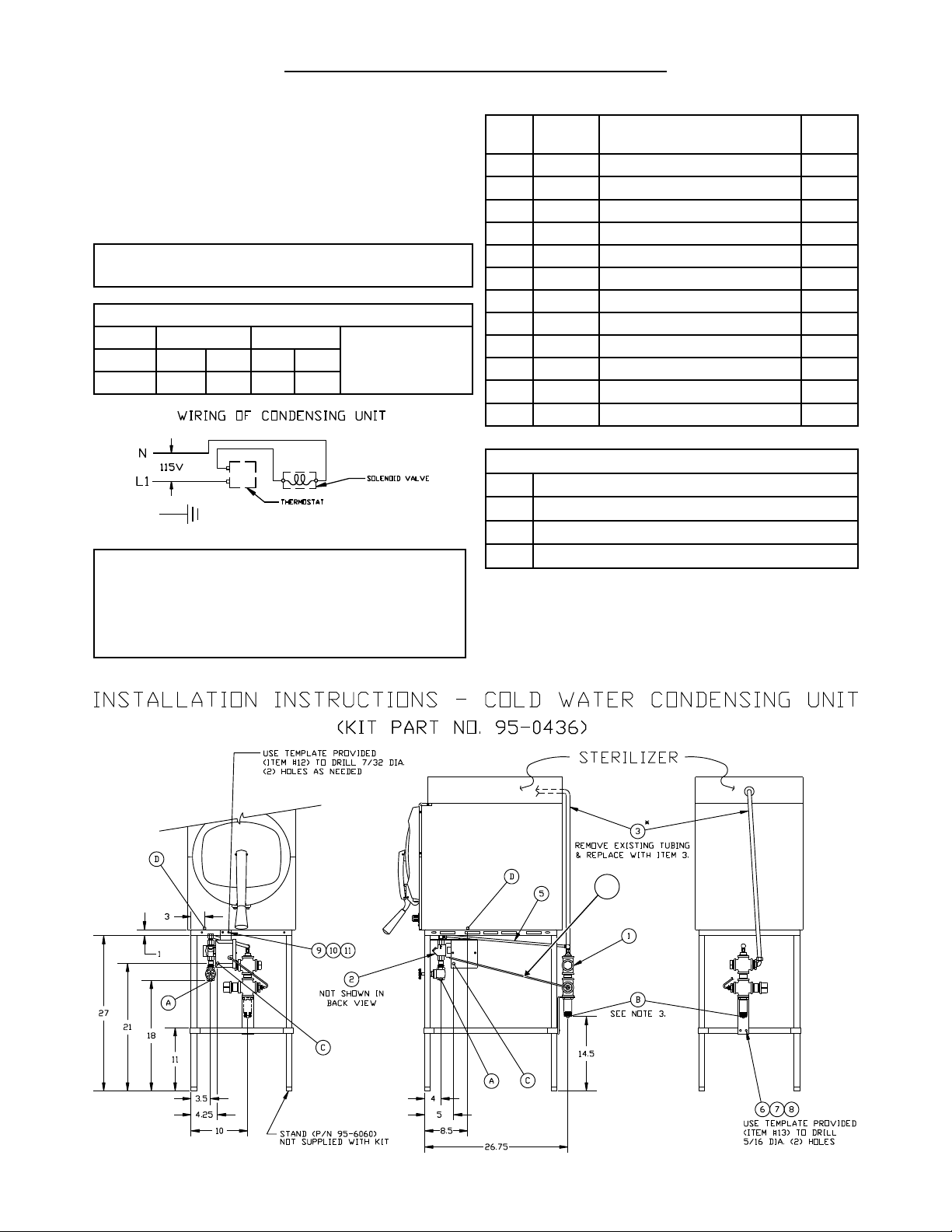
NOTES:
Unit must be grounded and all wiring to comply with local
1.
codes.
Pipe to open drain. Do not make solid connection to sewer.
2.
Condensing unit to bt installed. Requires a front to back pitch,
3.
shown in the illustration below (see A).
COLD WATER CONDENSER
PART
ITEM
1 95-2119 Steam condensing unit 1
2 95-2219 Thermostat
3 95-0086 Exhaust line 1
5 15-7057 Copper tubing 3/8
6 10-1775 Rd. Hd. Mach. Screw, 1/4-20 2
7 10-2500 Lockwasher, 1/4 2
8 10-2308 Hex Nut, 1/4-20 2
9 10-1812 Rd. Hd. Mach. Screw, 10-32 2
10 10-2505 Lockwasher, 10 2
11 10-2340 Hex Nut, 10-32 2
12 95-4009 Front
13 95-4010 Back Template (11” Lg) 1
A
B
C
D
NO. DESCRIPTION
Box Assy. 1
OD
Template (7” Lg) 1
SERVICE CONNECTIONS REQUIRED
1/2” IPS Cold Water Connection
1” IPS Drain Connection (See Note 3)
115V Elec. Connection 7/8 Ø knockout (cond. unit)
Electrical Connection
QTY.
22.25”
A
2
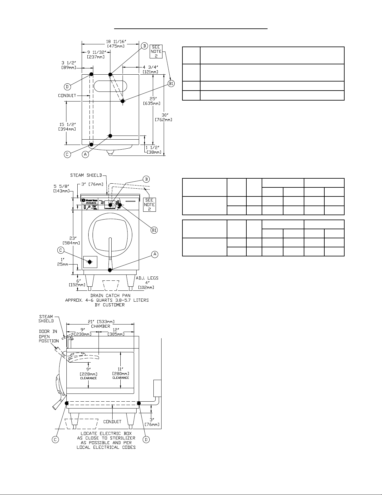
SECTION 1 INSTALLATION INSTRUCTIONS
REQUIRED CONNECTIONS:
A Drain - 1/2” (13mm) FPT of 5/8” (16mm) OD
copper (see note 1)
B Steam Exhaust Connection - 3/8” (10mm) IPS
(see note 2)
C Electrical Connection - (*see table below)
D Power Supply
ELECTRICAL REQUIREMENTS: Unit will be rated at
12kW at 236V and will be equipped for operation at:
□ 208-240V, 3 Wire, 1 Phase, 60 Hz
□ 208-240V, 4 Wire, 3 Phase, 60 Hz
□ 220V, 1 Phase, 50 Hz
□ 220V, 3 Phase, 50 Hz
AMP/PHASE
DOMESTIC
MODEL
STM-ED
kW Hz
9.3 60 45A - 26A -
12.4 60 - 52A - 30A
Single Phase
208V 240V 208V 240V
Three Phase
EXPORT
MODEL
STM-EDX
•
UNIT MUST BE GROUNDED
•
MAIN SUPPLY VOLTAGE FLUCTUATIONS ARE NOT TO
EXCEED ± 10% NOMINAL SUPPLY VOLTAGE
kW Hz
10.4 50 48A - 16A -
12.4 50 - 52A - 18A
Single Phase
220V 240V
Three Phase
220/380V 240/415V
NOTES:
An air break must be provided if a unit drain line is run.
1.
Vent exhaust to atmosphere. B1 is actual connection,
2.
but must exit casing at B.
IMPORTANT: Exhaust line must be vented to the outside to eliminate the exhaust steam and the accompanying noise from entering the room. Use 1/2” (13mm)
copper tubing or suitable alternate. The overall height
and length of the line should not rise more then 4’ (1.2
meters) above the unit and exceed 15’ (4.5 meters) with
a minimum of bends. The line should slope downward
after leaving the sterilizer in order to ensure condensate
drainage.
IMPORTANT: Failure to comply with this outline will af-
fect the sterilization process.
When an exhaust condenser is supplied; the following
services must be provided: 1/2” (13mm) IPS cold water:
1” (25mm) IPS waste: 115V electrical line.
3

SECTION 1 INSTALLATION INSTRUCTIONS
INSTRUCTIONS FOR INSTALLING PAN SUPPORTS AND BAFFLES
Locate the mounting studs on the inside of the chamber. There are two rack mounting studs on each side
1.
(see Fig. 1).
Taking one pan support and positioning rack so that the pan stop is facing the rear of the unit and the wires
2.
are facing toward the center of the unit. The pan stop is a piece of sheet metal welded to the rack with a 65° bend.
Begin to hang the pan support by placing the rear key-way slot onto the rear mounting stud and slide the rack
3.
until the slot sits on the mounting stud. When this is done correctly the front mounting stud will be in position
to place the front key-way slot. Slide the rack down into its correct position (see Fig 2).
After installing one pan support rack correctly, you can install the upper bafe. Position the bafe so that the
4.
45° bend is facing up towards the front of the unit (see Fig. 3). Slide the mounting tab onto the at bend on
the pan stop bracket. The bafe should now stay in place by itself, but in a tilted state (see Fig. 4).
Position the second pan support rack into the cavity and slide the other mounting tab onto the rack at bend
5.
while the pan support rack is not on the mounting studs. Hang the pan support by placing the rear key-way
slot onto the rear mounting stud and slide the rack until the slot sits on the mounting stud. When this is done
correctly the front mounting stud will be in position to place the front key-way slot. Slide the rack down into
its correct position.
Place the Perforated Water Bafe so that it sits on the bottom of the inside of the sterilizer chamber (see Fig. 5).
6.
CAUTION: Do not cover the holes in the Perforated Water Bafe by using it as a shelf. This will result in a
7.
disrupted ow of steam.
THE ELECTRIC SUPPLY CONNECTIONS FOR STM-ED: Connect to proper electrical supply as indicated on
nameplate on top of unit. The power supply cord is brought in from the rear of the unit, through the conduit and
the connection is made at the terminal box located at the front of the unit.
THE ELECTRIC SUPPLY CONNECTIONS FOR STM-EDX: Connect to proper electrical supply as indicated on
nameplate on top of unit. Connection is made from the rear of the unit, through the conduit to the terminal box
located at the front of the unit. All control circuits are 220 volts.
In order to accomplish this, a current-carrying grounded neutral must be provided.
Thus, a three phase system must be 4-wires. Most electrical codes require, and we recommend, that a separate
switch be located within sight of the sterilizer.
4
SECTION 1 INSTALLATION INSTRUCTIONS
SSR
3+
-
1
CONTROL
BOARD
2
1
2
1
2
4
9
8
3
7
2
1
P4
P13
PRINTER
1
2
J4
POWER
J3
J21
J21
J21
J21
J21
J5
J14
J1
J13
T1
POWER
LOW WATER LED
P21
P5
T1
THERMISTOR
PROBE
EXHAUST
VALVE
4
2
1
+
-
L
G
POWER
SUPPLY
5 VDC
K1
2
3
5
4
24
7
8
9
6
26
23
K3
LOW WATER
CUTTOFF
13
13
13
13
27
L1
L2
L1
L2
L1
L2
POWER
31
29
1.5 A
FUSE
1
5
20
N
28
22
L2 (2A)
L1 (1A)
L1
L2
L3
T2
T3
23
16
14
21
25
RS232
RS232
13
18
15
4
MK
22
HEATER 2
17
HEATER 1
T1
T2
K2 T1
T2
19
HEATER 3
T1
T2
25
11
10
12
WIRE YEL 22 GA
WIRE BRN 22 GA
WIRE RED 22 GA
WIRE RED 22 GA
WIRE RED 22 GA
WIRE BLU 18 GA
WIRE BLU 22 GA
WIRE RED 18 GA
WIRE BLK 22 GA
WIRE ORG 22 GA
WIRE ORG 22 GA
WIRE ORG 18 GA
WIRE ORG 22 GA
WIRE ORG 18 GA
WIRE RED 18 GA
WIRE BLK 18 GA
WIRE ORG 18 GA
WIRE RED 18 GA
30
WIRE BLU 18 GA
WIRE ORG 22 GA
WIRE ORG 22 GA
WIRE BLK 16 GA
WIRE RED 16 GA
WIRE WHT 16 GA
WIRE RED 16 GA
WIRE WHT 16 GA
WIRE BLK 16 GA
WIRE RED 18 GA
WIRE ORG 22 GA
WIRE ORG 22 GA
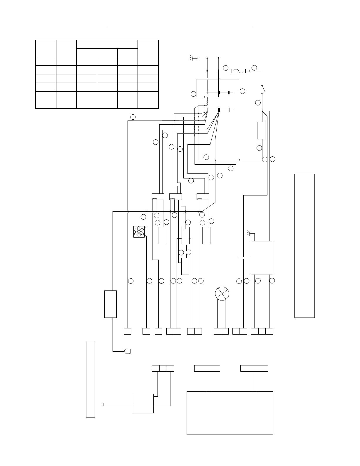
DIGITAL STERILMATIC MODEL STM-ED - 1 PHASE WIRING DIAGRAM
DRAWING No. 95-6311 Revision A - Date 10/25/13
DRAWING No. 95-6311 Revision A
Volts Phase
AMPs Per Line Wire
L1 L2 L3
kW
208 1 45 45 -- 9.3
208 3 26 26 26 9.3
220 1 48 48 -- 10.4
220 3 28 28 28 10.4
240 1 52 52 -- 12.4
240 3 30 30 30 12.4
5
SECTION 1 INSTALLATION INSTRUCTIONS
SSR
3+
-
1
CONTROL
BOARD
2
1
2
1
2
4
9
8
3
7
2
1
P4
P13
PRINTER
1
2
J4
POWER
J3
J21
J21
J21
J21
J21
J5
J14
J1
J13
C
C
T1
POWER
LOW WATER LED
P21
P5
T1
THERMISTOR
PROBE
EXHAUST
VALVE
4
2
1
+
-
L
G
POWER
SUPPLY
5 VDC
K1
2
3
5
4
24
7
8
9
6
26
23
LOW WATER
CUTTOFF
13
13
13
13
27
L1
L2
L1
L2
POWER
31
29
2.0 A
FUSE
1
5
20
N
1
22
L3 (3A)
L2 (2A)
L1 (1A)
30
L1L2L3
T2
T3
23
16
14
21
25
RS232
RS232
13
18
15
4
MK
22
WIRE RED 18 GA
WIRE BLK 22 GA
WIRE ORG 22 GA
WIRE YEL 22 GA
WIRE BRN 22 GA
WIRE RED 22 GA
WIRE RED 22 GA
WIRE ORG 22 GA
WIRE ORG 22 GA
WIRE BLK 16 GA
WIRE ORG 18 GA
WIRE ORG 22 GA
WIRE RED 22 GA
WIRE BLU 18 GA
WIRE BLU 22 GA
WIRE RED 16 GA
WIRE WHT 16 GA
WIRE RED 16 GA
WIRE BLK 16 GA
WIRE ORG 18 GA
WIRE BLU 18 GA
WIRE ORG 22 GA
WIRE RED 18 GA
WIRE ORG 18 GA
WIRE BLK 18 GA
WIRE RED 18 GA
WIRE WHT 16 GA
WIRE ORG 18 GA
WIRE RED 18 GA
WIRE ORG 22 GA
FAN
K3
L1
L2
HEATER 1
T1
T2
K2
T1
T2
HEATER 3
T1
T2
25
11
10
12
HEATER 2
17
19
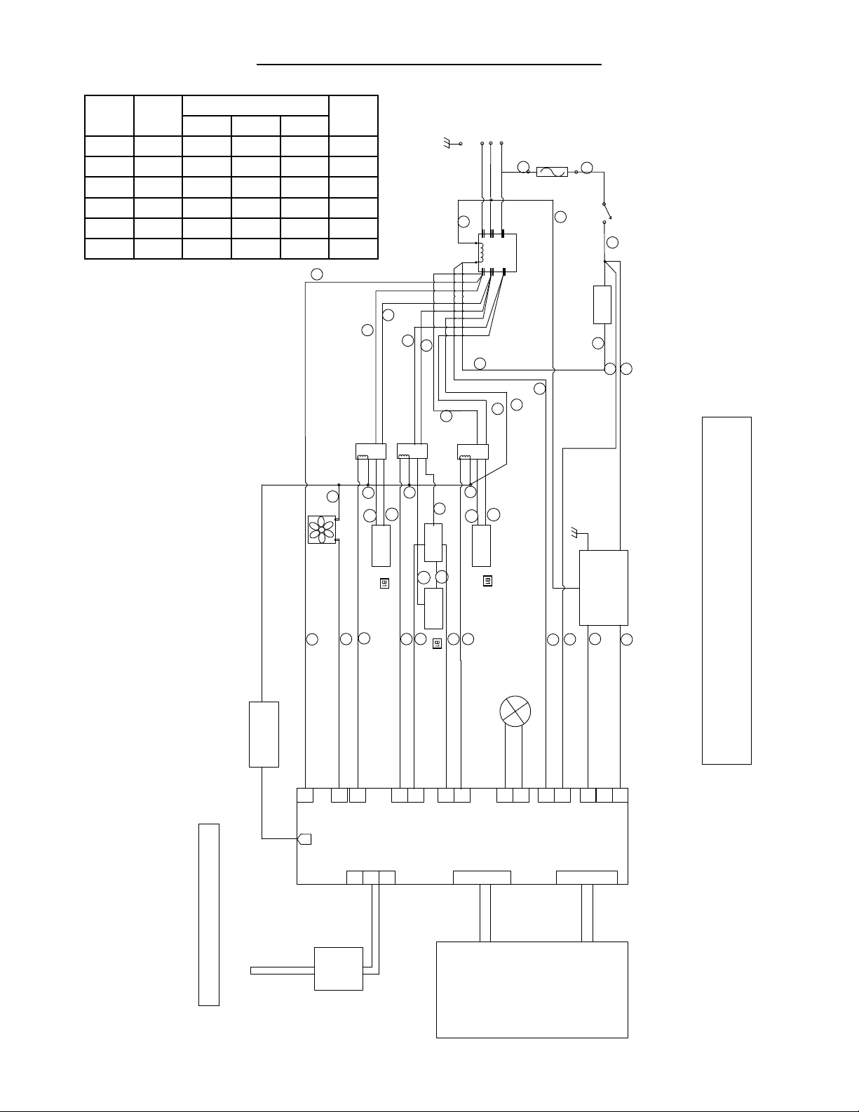
DIGITAL STERILMATIC MODEL STM-ED - 3 PHASE WIRING DIAGRAM
DRAWING No. 95-6312 Revision A - Date 10/25/13
DRAWING No. 95-6312 Revision A
Volts Phase
AMPs Per Line Wire
L1 L2 L3
kW
208 1 45 45 -- 9.3
208 3 26 26 26 9.3
220 1 48 48 -- 10.4
220 3 28 28 28 10.4
240 1 52 52 -- 12.4
240 3 30 30 30 12.4
6

SECTION 1 INSTALLATION INSTRUCTIONS
15
240 Volt, 3 Phase
240
240
16
23
13
25
14
18
21
40A
40A
40A
L
1
L2
L3
ELECTRICAL SOURCE UNIT WIRING
FUSE AND
DISCONNECTED MEANS
TYPICAL CIRCUIT CONNECTION FOR STM-ED STERILIZER
240
15
208 Volt, 3 Phase
208
208
16
23
13
25
14
18
21
40A
40A
40A
L
1
L2
L3
208
15
240 Volt, 1 Phase
240
21
16
23
18
25
14
13
60A
60A
L
1
L2
15
208 Volt, 1 Phase
208
21
16
23
18
25
14
13
50A
50A
L
1
L2
7

SECTION 1 INSTALLATION INSTRUCTIONS
1
4- Wire, 3 Phase
Delta (480/240V)
4- Wire, Wye Connected
380/220V, 3 Phase
240
240
8
2
12
19
25
7
5
20A
20A
20A
L
2
L1
N
N
L
3
480
ELECTRICAL SOURCE UNIT WIRING
FUSE AND
DISCONNECTED MEANS
TYPICAL CIRCUIT CONNECTION FOR STM-EDX STERILIZER -EXPORT-
480
415
415
20A
20A
20A
L
1
L2
L3
240
1
8
2
12
19
25
7
5
4- Wire, Wye Connected
415/240V, 3 Phase
N
380
380
20A
20A
20A
L
1
L2
L3
220
1
8
2
12
19
25
7
5
This page intentionally left blank.
8
 Loading...