

Page 1
INSTALLATION AND OPERATION
MANUAL AND PARTS LIST
GAS FIRED STEAMER
MODELS: STHE-7-TGG
STHE-12-TGG
STHE-16-TGG
WARNING
Improper installation, adjustment,
alteration, service or maintenance can
cause property damage, injury or death.
Read the installation, operating and
maintenance instructions thoroughly
before installing or servicing this
equipment.
FOR YOUR SAFETY
Do not store or use gasoline or other
flammable vapours and liquids in the
vicinity of this or any other appliance.
PRINTED IN CANADA
PART NUMBER 10225R0 1 2010-09-07
Page 2

INSTALLATION AND OPERATION MANUAL AND PARTS LIST,
MODELS: STHE-7-TGG, STHE-12-TGG, STHE-16-TGG
IMPORTANT NOTES FOR INSTALLATION AND OPERATION
Retain this manual for future reference.
NOTICE
Instructions to be followed in the event that the operator of this appliance
smells gas must be posted in a prominent location. This information shall be
obtained by consulting the local gas supplier.
IMPORTANT
Do not attempt to operate this unit in the event of power failure.
Adequate clearances must be maintained for safe and proper operation.
The appliance area must be kept free and clear of combustibles.
Do not obstruct the flow of combustion and ventilation air.
Contact the factory, the factory representative or a local service company to
perform maintenance and repairs should the appliance malfunction. Refer to
warranty terms.
PART NUMBER 10225R0 2 2010-09-07
Page 3

INSTALLATION AND OPERATION MANUAL AND PARTS LIST,
MODELS: STHE-7-TGG, STHE-12-TGG, STHE-16-TGG
TABLE OF CONTENTS
DESCRIPTION PAGE
1.0 SERVICE CONNECTIONS ................................................4
2.0 INTRODUCTION ........................................................5
3.0 PERFORMANCE CHECK ................................................12
4.0 OPERATION INSTRUCTIONS ............................................13
5.0 PREVENTIVE MAINTENANCE ............................................23
6.0 TROUBLESHOOTING ...................................................25
7.0 MAINTENANCE ........................................................33
8.0 PARTS LIST .........................................................34
PART NUMBER 10225R0 3 2010-09-07
Page 4
INSTALLATION AND OPERATION MANUAL AND PARTS LIST,
MODELS: STHE-7-TGG, STHE-12-TGG, STHE-16-TGG
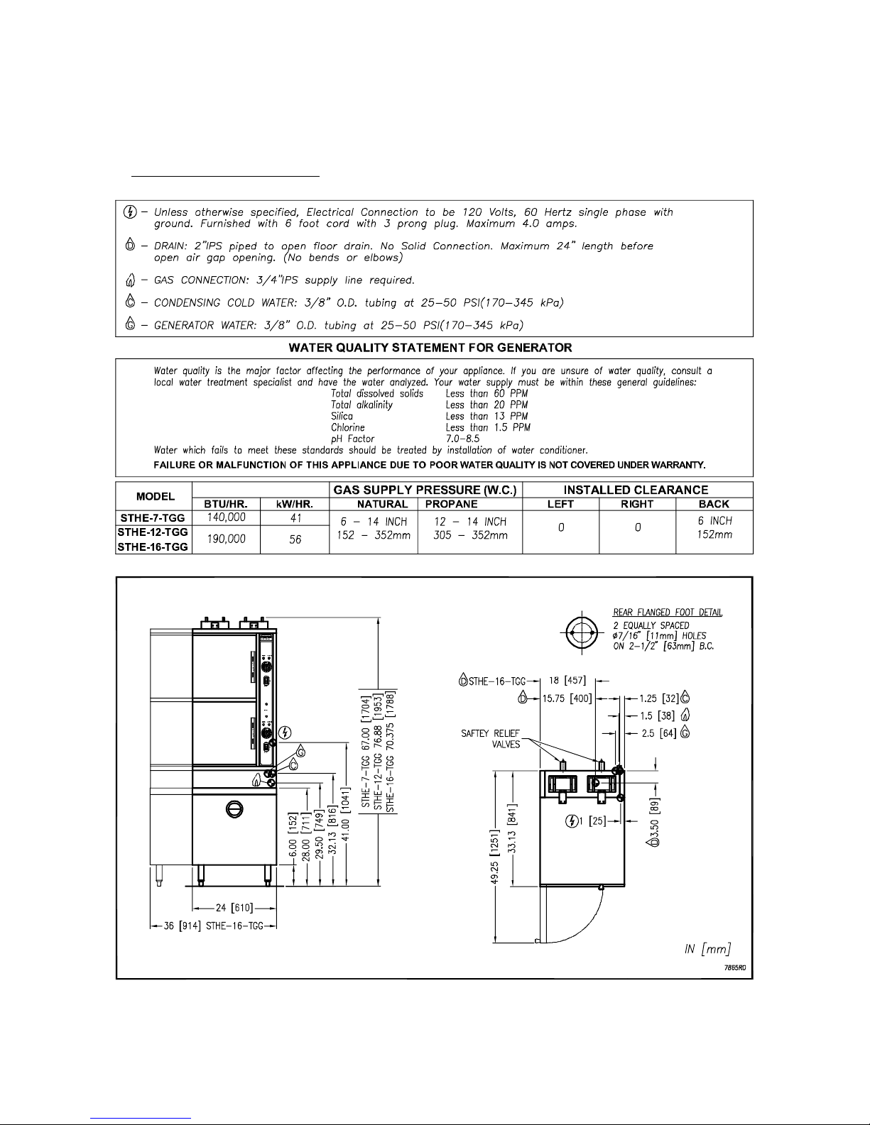
1.0 SERVICE CONNECTIONS
PART NUMBER 10225R0 4 2010-09-07
Page 5

INSTALLATION AND OPERATION MANUAL AND PARTS LIST,
MODELS: STHE-7-TGG, STHE-12-TGG, STHE-16-TGG
2.0 INTRODUCTION
DESCRIPTION
The STHE series steamers are pressureless steam cookers consisting of two independently
controlled compartments enclosed in a single cabinet. Each compartment is equipped with a
separate heavy duty door with inner gasket plate isolated from the exterior surface. Door
latches operate by action for positive sealing of inner door. Operation controls are displayed on
a single front-mounted panel and include separate timers with indicator lights for selection of
constant steam or 60-minute-long duration cooking. Two gas fired, stainless steel generators
operating at “0" psi (0 kPa) and rated at 70,000 BTU (STHE-7-TGG) or 95,000 BTU (STHE-12TGG and STHE-16-TGG) are located in the bottom cabinet and may be operated separately.
BASIC FUNCTIONING
The steamers may be operated with only one compartment in use; or both may be used
simultaneously. Each compartment is equipped with identical controls, allowing selection of
constant steam or 60-minute timer operation. The cooker becomes operational when it is set to
constant steam, or the timer is set at the desired cooking time and the compartment door is
closed.
When steam flowing inside the compartment has raised the interior temperature to 195 degrees
F, the contacts of a thermostatic switch close, completing the circuit to the timer motor and
starting the coking time period. At the end of the set interval, timer contacts switch to shut off
the cooking operation and sound a signal buzzer. The buzzer is silenced by returning the timer
dial to the OFF position. In the constant steam mode, operation will be continuous.
Steam emitted from the compartment along with liquid cooking drainage is directed through a
drain screen inside the compartment into the cooker drain line to the generator drain box that is
automatically actuated by a thermostatic cooling valve to condense the steam to water prior to
discharge into the floor drain.
PART NUMBER 10225R0 5 2010-09-07
Page 6

INSTALLATION AND OPERATION MANUAL AND PARTS LIST,
MODELS: STHE-7-TGG, STHE-12-TGG, STHE-16-TGG
INSTALLATION
SETTING IN PLACE
The location of installation must be under an exhaust hood, which will remove small amounts of
water vapor emitted when the cooker doors are opened, and exhaust fumes. Level the unit in
final location by turning the adjustable feet. Using the cabinet top as a reference, obtain level
adjustment left-to-right and front-to-back.
MECHANICAL CONNECTIONS
Since the Pressureless Cooker is interconnected at the factory to the steam boiler, no field
connections to the cooker are required. All electrical and plumbing connections are located on
the rear middle panel of the cabinet.
PART NUMBER 10225R0 6 2010-09-07
Page 7
INSTALLATION AND OPERATION MANUAL AND PARTS LIST,
MODELS: STHE-7-TGG, STHE-12-TGG, STHE-16-TGG
2.0 GENERAL
Gas installation to conform to local codes, or in absence of local codes, with the National Fuel
Gas Code - ANSI Z223.1/NFPA 54. In Canada installation to be in accordance with the Natural
Gas and Propane Installation Code, CSA B149.1. and or local codes.
1. The appliance and its individual shut off valve must be disconnected from the gas supply
piping system during any pressure testing of that system at pressures in excess of ½ psig
(3.45 kPa).
2. The appliance must be isolated from the gas supply piping system by closing its individual
manual shut off valve during any pressure testing of the gas supply piping system at test
pressures equal to or less than ½ psig (3.45 kPa).
Electrical grounding must be provided in accordance with local codes, or in the absence of local
codes, with the National Electrical Code ANSI/NFPA 70. In Canada, installation must be in
accordance with the Canadian Electrical Code CSA C22.2.
WARNING: Electrical grounding instructions - Units come equipped
with a three-prong (grounding) plug for your protection against
shock hazard and should be plugged directly into a properly
grounded three-prong receptacle. Do not cut or remove the
grounding prong from this plug. (120 VOLT UNITS ONLY)
WIRING DIAGRAM FOR APPLIANCE IS LOCATED ON RIGHT HAND SIDE PANEL OF THE
COOKER CABINET.
2.1 EXHAUST FANS AND CANOPIES:
Canopies are set over ranges, ovens, kettles, etc., for ventilation purposes. It is
recommended that a canopy extend 6" past the appliance and be located 6' 6" from the
floor. Filters should be installed at an angle of 45 degrees or more with the horizontal.
This position prevents dripping of grease and facilitates collecting the run-off grease in a
drip pan, usually installed with the filter. A strong exhaust fan tends to create a vacuum in
the room and may interfere with burner performance or may extinguish pilot flames.
Makeup air openings approximately equal to the fan area will relieve such vacuum. In
case of unsatisfactory performance on any appliance, check with the exhaust fan in the
“OFF” position.
2.2 WALL EXHAUST FAN:
The exhaust fan should be installed at least two feet above the vent opening at the top of
the unit.
PART NUMBER 10225R0 7 2010-09-07
Page 8
INSTALLATION AND OPERATION MANUAL AND PARTS LIST,
MODELS: STHE-7-TGG, STHE-12-TGG, STHE-16-TGG
INSTALLATION (Continued)
2.3 CLEARANCES:
Adequate clearance must be provided in aisle and at the side and back. Adequate
clearances for air openings into the combustion chamber must be provided, as well as for
serviceability for use on noncombustible floors. Minimum clearance from combustible and
noncombustible construction, 0" on left side, 0" on right side and 6" from back.
WARNING: These procedures must be followed by qualified
personnel or warranty will be voided. An open gap floor drain is
required immediately below the appliance drain.
To Install:
1. Uncrate carefully. Report any freight damage to the freight company immediately.
2. Set the unit in place. Be certain to maintain the minimum clearances from combustibles
and non-combustibles.
3. For an appliance supplied with legs, level the appliance using a spirit level. Should
flanged adjustable feet be provided, anchor to floor using proper anchoring devices.
4. Seal bolts and flanged feet with Silastic or other equivalent compound.
5. Be certain to leave adequate clearances for cleaning, maintenance and service.
PART NUMBER 10225R0 8 2010-09-07
Page 9

INSTALLATION AND OPERATION MANUAL AND PARTS LIST,
MODELS: STHE-7-TGG, STHE-12-TGG, STHE-16-TGG
INSTALLATION (Continued)
GAS CONNECTION:
1. The Serial and Rating Plate on the unit indicates the type of gas your unit is equipped to
burn. DO NOT connect to any other gas type.
2. A ¾” NPT line is provided at rear for the connection. Each compartment is equipped with
an internal pressure regulator which is set at 3.5" W.C. manifold pressure for natural gas
and 10" W.C. for propane gas. Use c” pipe tap on the burner manifold for checking
pressure.
An adequate gas supply is imperative. Undersized or low pressure lines will restrict the volume
of gas required for satisfactory performance. A steady supply pressure, between 6" W.C. and
14" W.C. for natural gas and 11" W.C. and 14" W.C. for propane gas is recommended. With all
units operating simultaneously, the manifold pressure on all units should not show any
appreciable drop. Fluctuations of more that 25% on natural gas and 10% on propane gas will
create problems, affecting burner operation. Contact your gas company for correct supply line
sizes.
Purge the supply line to clean out any dust, dirt or other foreign matter before connecting the
line to the unit. Use pipe joint compound which is suitable for use with Liquid Propane on all
threaded connections.
Test pipe connections thoroughly for gas leaks.
Use soapy water only for testing on all gases.
Never use an open flame to check for gas leaks.
All the connections must be checked for leaks
after the unit has been put in operation.
ELECTRICAL CONNECTION:
120 VAC-60 Hz - Single Phase
Units with this electrical rating are factory supplied with a three-wire cord and three-prong plug
which fits any standard 120V, three-prong grounded receptacle. A separate 15 amp supply is
needed for each unit.
PART NUMBER 10225R0 9 2010-09-07
Page 10
INSTALLATION AND OPERATION MANUAL AND PARTS LIST,
MODELS: STHE-7-TGG, STHE-12-TGG, STHE-16-TGG
INSTALLATION (Continued)
PLUMBING CONNECTIONS:
WARNING: Plumbing connections must comply with applicable
Sanitary, Safety and Plumbing Codes.
Two water lines are provided. Connect water supply lines to the 3/8" copper tubes at the rear of
the steamer.
One line is for supply of water to the generator and one for cold condensate water to condense
live steam entering the drain line.
DRAIN CONNECTIONS:
Appliance drain is 2 inch pipe size. Provide open air gap type drain.
WARNING: An open gap floor drain is required immediately below
the appliance drain.
CAUTION: PVC OR CPVC are not acceptable materials for drains.
PART NUMBER 10225R0 10 2010-09-07
Page 11

INSTALLATION AND OPERATION MANUAL AND PARTS LIST,
MODELS: STHE-7-TGG, STHE-12-TGG, STHE-16-TGG
INSTALLATION (Continued)
COLD WATER CONDENSER:
The steamer is equipped with a cold water condenser, in the rear of the cooking chamber,
which helps to condense the steam prior to discharge into the drain. The steamer freely vents
itself by the negative pressure created by the condensate water drainage. This negative
pressure prevents steam leakage around the door gasket and helps draw the steam through
the cooking compartment. Steam leakage at the door may indicate a plugged or improperly
installed drain.
Temperature of condensate water flowing through the drain is controlled by the thermostatic
cooling valve (TCV) located inside the controls compartment on the right side of the unit. The
valve has been factory set to keep condensate water flowing into the drain at or below 140°F.
Depending on local plumbing code requirements, this setting may be changed to obtain a
different maximum drainage temperature. Refer to next section Performance Check for
instructions to set the (TCV).
WATER CONDITIONING:
It is important that the water supplied to the generator be softened to no more than 2.0 grains of
hardness and have a pH of 7.0 to 8.5. This degree of hardness can be easily obtained with the
use of a properly maintained water softener. The use of a water meter will determine the water
consumption and when the water softener needs regeneration or recharging. Failure to comply
with these water condition standards may void the warranty.
Untreated water contains scale producing minerals which can precipitate onto the surfaces in
the steam generator. Due to the temperatures in the steam generator, the minerals can bake
onto the surfaces and components. This can result in early component failure and reduced
product life. Water level probes become coated with scale. Scale may bridge across the probe
insulator from the metal extension which senses the water level in the steam generator shell.
Once this scale becomes wet, the water level control is unable to maintain the proper water
level in the steam generator.
STRAINERS and FILTERS will NOT remove minerals from the water.
PART NUMBER 10225R0 11 2010-09-07
Page 12
INSTALLATION AND OPERATION MANUAL AND PARTS LIST,
MODELS: STHE-7-TGG, STHE-12-TGG, STHE-16-TGG
3.0 PERFORMANCE CHECK
WARNING: The steamer and its parts are hot. Use care when
operating, cleaning or servicing the steamer. The cooking
compartment contains live steam. Stay clear while opening door.
Once the steamer is installed and all mechanical connections have been made, thoroughly test
the steamer before operation.
1. Check that proper water, drain and electrical and gas connections have been made.
2. Turn main power switch ON.
3. Check that “Ignition” light comes on and that burners ignite.
4. After approximately 15 minutes, the “READY” light should come on, indicating that the water
temperature has reached 205º Fahrenheit (97º Celsius). At this time, set timer to the “5
minute” position. With door open, observe that no steam is entering the compartment and
that the “COOKING” light is OFF.
5. Close compartment door. The COOKING light should now illuminate and steam should be
heard entering the compartment shortly after.
6. After five minutes of operation check that water from the cold water condenser is flowing
through the drain line.
7. Open compartment door and observe that steam supply to compartment is cut off.
“READY” light should again come on as “COOKING” light turns “OFF”.
8. Close compartment door and observe cooker operation for several minutes. Operation is
correct if timer dials begin to rotate after a short delay period required for preheating. After
the delay period plus the “5-Minute” initial setting, the timer dials will return to the “0-Minute”
position, at which a buzzer sounds. The buzzer is silenced by turning the dial to the “OFF”
position.
9. With all compartments of the steamer operating in the cooking cycle, check the temperature
of the condensate coming out the drain. If the drain temperature exceeds local plumbing
code requirements, adjust the Thermostatic Cooling Valve (TCV) out for a lower drain
temperature and in for a higher drain temperature. A TCV setting of approximately 2.75
yields a drain temperature of 140°F. A setting of approximately 2.5 or 3 yields temperatures
of 125°F and 155°F, respectively.
PART NUMBER 10225R0 12 2010-09-07
Page 13
INSTALLATION AND OPERATION MANUAL AND PARTS LIST,
MODELS: STHE-7-TGG, STHE-12-TGG, STHE-16-TGG
4.0 OPERATION INSTRUCTIONS
LIGHTING
1. Ensure power, gas and water supply is on.
2. Turn power switch “ON”.
3. Steam generator tanks will begin filling with water.
4. Once proper water level has been reached, the ignition light will come on and should remain
on until the ready light comes on.
5. Cooker is now ready for use.
Your steamer has been factory set, when “ON” to maintain water temperature during the
READY phase at approximately 205º Fahrenheit (97º Celsius) just below water boiling point.
WARNING: In the event of main burner ignition failure, a 5 minute
purge period must be observed prior to re-establishing ignition
source.
WARNING: In the event a gas odor is detected, shut down
equipment at the main shut off valve and contact the local gas
company or gas supplier for service.
PART NUMBER 10225R0 13 2010-09-07
Page 14

INSTALLATION AND OPERATION MANUAL AND PARTS LIST,
MODELS: STHE-7-TGG, STHE-12-TGG, STHE-16-TGG
4.0 OPERATION INSTRUCTIONS (Continued)
PREHEATING
Before each initial operation of the cooker, and at any other time when the cooking
compartment is cold, a 1-minute preheating period is required. To preheat the cooker, put
steam source into operation and proceed as follows:
1. Close cooking compartment door.
2. Set 60-Minute Timer Dial (1) to “1-minute” setting.
NOTE: Total elapsed preheating time equals the timer setting plus a short delay period
needed to activate a thermostatic switch included in the controls.
3. Turn off buzzer, which sounds to indicate cooking is complete, by setting the
Timer Dial (1) to OFF position.
COOKING
Before loading the cooker, be sure compartment is hot. See preheating instructions.
1. Slide pans of food into cooking compartment pan supports.
2. Close cooking compartment door.
3. Set timer cooking time:
a. CONSTANT STEAM - for continuous cooking
b. 60-MINUTE TIMER - for timed cooking.
4. Set appropriate timer to the required cooking time (see Cooking Guidelines).
5. Turn off buzzer, which sounds to indicate cooking is complete, by setting timer dial (1) to
the OFF position.
6. Open door slightly at first letting most of the steam out of the compartment and then
fully open the door.
7. Unload by sliding pans of food from pan supports.
PART NUMBER 10225R0 14 2010-09-07
Page 15
INSTALLATION AND OPERATION MANUAL AND PARTS LIST,
MODELS: STHE-7-TGG, STHE-12-TGG, STHE-16-TGG
4.0 OPERATION INSTRUCTIONS (Continued)
SHUT-DOWN PROCEDURE
No shut-down procedure is required for the cooker except to check that both timer dials (1) are
in the OFF position and that both compartment doors are open. When all cooking has been
completed for the day, the steam source must be shut off.
COMPLETE SHUTDOWN
a. Set timer to “OFF” and turn power switch “OFF”. Steam generator will drain automatically.
b. Turn water supply “OFF”.
c. Close manual gas shutoff valve.
d. Disconnect power supply.
CAUTION: When the unit is not in use, leave the cooking
compartment door slightly ajar to prolong the life of the door gasket.
CLEANING
After each period of daily operation (more frequently as required to maintain cleanliness), the
cooker should be thoroughly cleaned by completing the following steps:
1. Remove left and right side pan supports and drain screens by lifting up and off mounting
studs. Remove drain screen by pulling straight out. Wash with a mild detergent. Rinse and
set aside for reassembly.
2. Wash cooking compartment interior using a mild detergent and water. Rinse and dry
thoroughly.
3. Replace pan supports and drain screens in compartment and leave door open.
DRAINAGE
Cooking Compartment Drainage
The bottom of the cooking compartment is angled slightly toward the rear of the unit. This
assures that any condensate build-up or spills will be directed toward the drain, which is located
at the rear bottom center of the cooking compartment. Any liquid exiting the cooking
compartment runs down the cooking compartment drain tube and into the drain line.
PART NUMBER 10225R0 15 2010-09-07
Page 16

INSTALLATION AND OPERATION MANUAL AND PARTS LIST,
MODELS: STHE-7-TGG, STHE-12-TGG, STHE-16-TGG
4.0 OPERATION INSTRUCTIONS (Continued)
Drip/Spill Trough Drainage
The Pressureless Steam Cookers have a drip/spill trough below the cooking compartment door.
It will catch any condensate gathering on the front of the unit when the door is opened.
WARNING: The steamer and its parts are hot. Use care when
operating, cleaning or servicing the steamer. The cooking
compartment contains live steam. Stay clear when opening door.
CAUTION: An obstructed drain can cause personal injury or
property damage.
CONTROLS
1. Ignition Light When lit, indicates burners have been ignited
and are heating the steam generator tank.
2. Ready Pilot Light When lit, indicates steam generator has reached
205º Fahrenheit (97º Celsius) and is ready for
the cooking cycle.
3. Cooking Pilot Light When lit, indicates that a cooking cycle is in
progress.
4. Timer /Constant Steam Set the cooking time (0 to 60 minutes) - steam
cooking will begin when the door is closed. The
cooking cycle will be interrupted if the door is
opened during the cooking cycle; resume
cooking by closing the door. Constant Steam For continuous cooking.
5. Main Power Switch
DELIME Closes the drain valve while CLR liquid is being poured into
the steam generator during the Delime procedure. Amber
light will ignite on the main power switch.
ON The steam generator will automatically fill and begin heating to the pre-set temperature. Red light
will ignite on the main power switch.
OFF The steam generator will drain. No lights.
6. Buzzer Signals end of cooking period (not shown).
PART NUMBER 10225R0 16 2010-09-07
Page 17

INSTALLATION AND OPERATION MANUAL AND PARTS LIST,
MODELS: STHE-7-TGG, STHE-12-TGG, STHE-16-TGG
4.0 OPERATION INSTRUCTIONS (Continued)
NOTE
Each cooking compartment has its own steam generator
and controls and can be operated independently.
TEST KITCHEN BULLETIN
Pressureless Cooker - Facts On Parade
1. Frozen vegetables should always be cooked in perforated 12" x 20" x 2 ½ “ (1/1 65 mm)
pans 7 ½ lb (34 kg) maximum per pan.
2. Frozen entrees should be underlined with a perforated pan for best results. If they are
defrosted first, the heating time will be decreased.
3. Fresh foods may also be cooked in this unit. Vegetables and other foods where the stock
is not to be retained should be cooked in perforated 12" x 20" x 2 ½" (1/1 65 mm) pans for
the most nutritious results.
4. There is a thermostatic time delay built into this unit which adapts the unit to the proper
cooking time. This means that the total time will usually be longer than the time setting.
5. There is a safety microswitch on the door which shuts off the steam each time the door is
opened if the unit is in the cooking cycle.
6. Both compartments may be filled and timers set simultaneously.
7. Total cooking time will vary depending on the load, even though the timer setting is the
same.
8. All foods, except cakes and pastry, can be cooked in a steam cooking unit.
9. Steam cooked meals have greater nutritional value since they retain most of their vitamins
and minerals.
10. Because foods are cooked faster by the higher temperatures of steam cooking, they can
be prepared closer to serving time, insuring maximum freshness.
11. Steam cooked foods have a higher percent yield more portions per dollar spent.
PART NUMBER 10225R0 17 2010-09-07
Page 18

INSTALLATION AND OPERATION MANUAL AND PARTS LIST,
MODELS: STHE-7-TGG, STHE-12-TGG, STHE-16-TGG
TEST KITCHEN BULLETIN
12. Food may be served from the same pan in which it is steam cooked, thus reducing food
breakage since there is no extra handling or transferring of food from cooking pans to
serving pans. It also reduces pot washing tasks.
13. Some important advantages of steam cooking are labor saving, reduced operating costs,
space saving, and the lifting of heavy stock pots is eliminated.
14. Rice and spaghetti products, if thoroughly wet at the start of the cooking process, are very
easily prepared.
15. Food such as potatoes, poultry, seafood, and some meats may be blanched in the steam
cooker, thus reducing the total cooking time and grease absorption.
16. Fuel is used only when the steam cooking unit is in operation.
17. The steam cooker will loosen foods burned on pans making washing easier.
18. Solid pans are recommended when liquid is to be retained and perforated pans when the
liquid is not to be retained.
19. Eggs may be cooked out of the shell if they are to be chopped which eliminates peeling
after steaming.
20. The steam cooker can be opened during the cooking period to add or remove items.
21. Steam cooking information, including recommended pan size and type, weight per pan,
cooking times and pan yields are given on the following pages of this bulletin.
STEAM COOKING
The Pressureless Cooker is a two compartment unit. The STHE-7-TGG holds seven 12" x 20"
x 2- ½" or four 12" x 20" x 4" pans. The STHE-12-TGG holds twelve 12" x 20" x 2-½” or six 12"
x 20" x 4" pans. The STHE-16-TGG holds sixteen 12" x 20" x 2-½” or eight 12" x 20" x 4" pans.
This enables the cook to prepare foods close to the time of service. The cooking times given
are timer settings and should be set on a preheated compartment. There is a thermostatic time
delay in each compartment that adjusts the total time depending on the temperature and
amount of the food. Therefore, the total time will be greater than the timer setting. At the end
of the timer cooking cycle the buzzer will sound, steam will stop flowing and the food can be
removed.
PART NUMBER 10225R0 18 2010-09-07
Page 19

INSTALLATION AND OPERATION MANUAL AND PARTS LIST,
MODELS: STHE-7-TGG, STHE-12-TGG, STHE-16-TGG
COOKING GUIDELINES
The following guidelines given are suggested quantities, time settings and estimated numbers
of orders per pan.
COOKING GUIDELINES
MISCELLANEOUS
ITEM
Eggs,
In Shell
Eggs,
Out of Shell
Rice,
Bulletin 16 gives
direction
Spaghetti,
Bulletin 13 gives
direction
FROZEN VEGETABLES
ITEM
WEIGHT PER
PAN
3 dozen 2 ½" (65 mm) 1-3 9-11 36
4 dozen 2 ½" (65 mm) 1-3 6-8 48
4 lbs (1.8 kg) 2 ½" (65 mm) 1-2 18-22 60-65 3 oz (85 g)
3 lbs (1.4 kg) 4" (65 mm) 1-2 18-22 40-45 (115 g)
APPROXIMATE
FROZEN
WEIGHT PER
PAN
RECOMMENDED
12" X 20" (1/1)
PERFORATED
PAN
RECOMMENDED
12" X 20" (1/1)
PERFORATED
PAN
NUMBER OF
PANS
NUMBER OF
PANS
TIMER
SETTINGS IN
MINUTES
TIMER
SETTINGS IN
MINUTES
APPROX.
NUMBER
COOKED
SERVINGS
PER PAN
1 egg each
1 egg each
APPROXIMATE
NUMBER
COOKED
SERVINGS
PER PAN
Asparagus Spears 7 ½ lbs (3.4 kg) 2 ½" (65 mm) 1-3 12-15 30 3 oz (85 g)
Beans, Green
Regular
Beans, Green
French Cut
Beans, Lima 7 ½ lbs (3.4 kg) 2 ½" (65 mm) 1-3 12-15 30 3 oz (85 g)
Broccoli 6 lbs (2.7 kg) 2 ½" (65 mm) 1-3 4-6 25 3 oz (85 g)
Brussel Sprouts 7 ½ lbs (3.4 kg) 2 ½" (65 mm) 1-3 10-15 30 3 oz (85 g)
Carrots 6 lbs (2.7 kg) 2 ½" (65 mm) 1-3 10-15 25 3 oz (85 g)
Cauliflower 6 lbs (2.7 kg) 2 ½" (65 mm) 1-3 7-12 25 3 oz (85 g)
Corn-Cut 7 ½ lbs (3.4 kg) 2 ½" (65 mm) 1-3 8-12 30 3 oz (85 g)
Mixed Vegetables 7 ½ lbs (3.4 kg) 2 ½" (65 mm) 1-3 8-12 30 3 oz (85 g)
6 lbs (2.7 kg) 2 ½" (65 mm) 1-3 10-15 25 3 oz (85 g)
6 lbs (2.7 kg) 2 ½" (65 mm) 1-3 5-7 25 3 oz (85 g)
PART NUMBER 10225R0 19 2010-09-07
Page 20

INSTALLATION AND OPERATION MANUAL AND PARTS LIST,
MODELS: STHE-7-TGG, STHE-12-TGG, STHE-16-TGG
FROZEN VEGETABLES
Peas (Loose) 7 ½ lbs (3.4 kg) 2 ½" (65 mm) 1-3 3-5 30 3 oz (85 g)
Spinach 9 lbs (4 kg) 2 ½" (65 mm) 1-3 Must be defrosted 30 4 oz (115 g)
Squash 12 lbs (5.4 kg) 2 ½" (65 mm) 1-3 Must be defrosted 50 3 oz (85 g)
FROZEN PREPARED ENTREES
ITEM
Lobster Tails,
6-8 oz
(170-255 g)
Shrimp, C.D.P. 16-20 lbs (7-9 kg) 2 ½" (65 mm) 1-3 8-11 75 3 oz (85 g)
Shrimp, Raw 16-20 lbs (7-9 kg) 2 ½" (65 mm) 1-3 11-15 50 3 oz (85 g)
Bulk Pack,
Frozen
Bulk Pack,
Defrosted
WEIGHT PER
PAN
7-8 lbs
(3.2-3.6 kg)
3½-4 lbs
(1.6-1.8 kg)
3½-4 lbs
(1.6-1.8 kg)
RECOMMENDED
12" X 20" (1/1)
PERFORATED
PAN
2 ½" (65 mm) 1-3 15-25 15 6 oz (170 g)
2 ½" (65 mm) 1-3 11-15 10 6 oz (170 g)
2 ½" (65 mm) 1-3 25-35 10 6 oz (170 g)
NUMBER OF
PANS
TIMER
SETTINGS IN
MINUTES
APPROXIMATE
NUMBER
COOKED
SERVINGS
PER PAN
PART NUMBER 10225R0 20 2010-09-07
Page 21

VEGETABLES
INSTALLATION AND OPERATION MANUAL AND PARTS LIST,
MODELS: STHE-7-TGG, STHE-12-TGG, STHE-16-TGG
COOKING GUIDELINES (Continued)
ITEM
Beans, Snap Green
or Waxed
Beets (50 mm)
2" Diameter
Broccoli, ½ - ¾"
(12-20 mm) Stalks
Carrots, Sliced 9 lbs (4 kg) 2 ½" (65 mm) 1-3 18-21 35-40 3 oz (85 g)
Cauliflower,
Trimmed, 1 ½-2"
(38-50 mm)
Corn on Cob,
Husked
Cabbage 1/4-1/6 of
Head, Cored
Onions, 2" (50 mm)
Diameter
Peas, Shelled 5 lbs (2.25 kg) 2 ½" (65 mm) 1-3 5-6 25-30 3 oz (85 g)
APPROX.
FROZEN
WEIGHT PER
PAN
6 lbs (2.7 kg) 2 ½" (65 mm) 1-3 18-22 25-30 3 oz (85 g)
7 ½ lbs (3.4 kg) 2 ½" (65 mm) 1-3 40-50 30-35 3 oz (85 g)
6 lbs (2.7 kg) 2 ½" (65 mm) 1-3 14-18 25-30 3 oz (85 g)
6 lbs (2.7 kg) 2 ½" (65 mm) 1-3 12-16 30-35 3 oz (85 g)
1 dozen 2 ½" (65 mm) 1-3 10-15 12
5 lbs (2.25 kg) 2 ½" (65 mm) 1-3 14-18 15-20 4 oz
6 lbs (2.7 kg) 2 ½" (65 mm) 1-3 20-25 25-30 4 oz (85 g)
RECOMMENDED
12" X 20" (1/1)
PERFORATED
PAN
NUMBER OF
PANS
TIMER
SETTINGS IN
MINUTES
APPROXIMATE
NUMBER
COOKED
SERVINGS
PER PAN
(115 g)
Potatoes, French
Fry Cut
Potatoes, Regular
Cut, 3" (75 mm)
Spinach, Cleaned
Cut
Squash, Summer,
Sliced 1" Thick
(25 mm)
Squash, Winter
Peeled
Turnip, Diced 5 lbs (2.25 kg) 2 ½" (65 mm) 1-3 28-32 20-25 4 oz
10 lbs (4.5 kg) 2 ½" (65 mm) 1-3 18-21 50 3 oz (85 g)
10 lbs (4.5 kg) 2 ½" (65 mm) 1-3 35-40 50 3 oz (85 g)
3 lbs (1.4 kg) 2 ½" (65 mm) 1-3 3-5 10-12 3 ¾oz
(105 g)
7 lbs (3.2 kg) 2 ½" (65 mm) 1-3 7-10 30-35 3 oz (85 g)
9 lbs (4 kg) 2 ½" (65 mm) 1-3 10-15 25-30 3 oz (85 g)
(115 g)
PART NUMBER 10225R0 21 2010-09-07
Page 22

INSTALLATION AND OPERATION MANUAL AND PARTS LIST,
MODELS: STHE-7-TGG, STHE-12-TGG, STHE-16-TGG
VEGETABLES - CANNED
COOKING GUIDELINES (Continued)
ITEM
Vegetables,
Canned
MEAT - POULTRY - FISH
ITEM
Chicken, Cut-up 8 lbs (3.64 kg) 2 ½" (65 mm) 1-3 20-30 15-20 2 oz
Chicken, 4 lbs
Whole
Fowl, 5 lbs or more,
Whole
Fish, Fillets 3 lbs (1.4 kg) 2 ½" (65 mm) 1-3 10-15 12-15 2 oz (55 g)
Frankfurters 5 lbs (2.3 kg) 2 ½" (65 mm) 1-3 3-5 35-40 2 oz (55 g)
WEIGHT PER
PAN
7 lbs (3.2 kg) 2 ½" (65 mm) 1-3 5-10 25-30 3 oz (85 g)
APPROX.
FROZEN
WEIGHT PER
PAN
3 each 4" (100 mm) 1-3 45-50 25-30 2 oz Protein
2 each 4" (100 mm) 1-3 50-60 20-25 2 oz Protein
RECOMMENDED
12" X 20" (1/1)
PERFORATED
PAN
RECOMMENDED
12" X 20" (1/1)
PERFORATED
PAN
NUMBER OF
PANS
NUMBER OF
PANS
TIMER
SETTINGS IN
MINUTES
TIMER
SETTINGS IN
MINUTES
APPROXIMATE
NUMBER
COOKED
SERVINGS
PER PAN
APPROXIMATE
NUMBER
COOKED
SERVINGS
PER PAN
Protein (55 g)
(55 g)
(55 g)
Hamburgers, 3 oz
(85 g)
Meatballs, 1 oz
(30 g), size*
Meatloaf* 15 lbs (6.8 kg) 2 ½" (65 mm) 1-3 40-50 50-60 2 oz Protein
Pork Chops, 4 oz.
Loin Bone (115 g)
Sausage, 1 ½ oz
(45 g)
Turkey, On Carcass 20-22 lbs
5 lbs (2.3 kg) 2 ½" (65 mm) 1-3 18-22 20-25 2 oz Protein
6 lbs (2.7 kg) 2 ½" (65 mm) 1-3 20-25 20-25 2 oz Protein
6 lbs (2.7 kg) 2 ½" (65 mm) 1-3 25-30 24 2 oz Protein
6 lbs (2.7 kg) 2 ½" (65 mm) 1-3 18-21 18-20 oz (55 g)
2 ½" (65 mm) 1 2 - 2 ½ hours 50-65 2 oz Protein
(9-10 kg)
(55 g)
(55 g)
(55 g)
(55 g)
(55 g)
* Raw weight for Meatballs and Meatloaf includes hamburger and extenders and yields 2 oz
(55 g) protein plus extenders or 3 oz (85 g) total portion.
PART NUMBER 10225R0 22 2010-09-07
Page 23

INSTALLATION AND OPERATION MANUAL AND PARTS LIST,
MODELS: STHE-7-TGG, STHE-12-TGG, STHE-16-TGG
5.0 PREVENTIVE MAINTENANCE
A good preventive maintenance program begins with the daily cleaning procedure. Additional
preventive maintenance operations are presented in this section. In establishments that
employ full-time maintenance personnel, the tasks described can be assigned to them. For
other installations, tasks requiring mechanical or electrical experience should be performed by
an authorized service agency.
The following paragraphs set for minimum preventive maintenance procedures that must be
completed periodically to assure continued trouble-free operation of the cooker.
CAUTION: Under no circumstances should hardware (or parts) be
replaced with a different length, size, or type other than as specified
in the parts list. The hardware used in the cooker has been selected
or designed specifically for its application, and the use of other
hardware may damage the equipment and will void any warranty.
NOTICE
As a safety precaution, disconnect the power supply during
cleaning or servicing.
WARNING: The steamer and its parts are hot. Use care when
operating, cleaning or servicing the steamer. The cooking
compartment contains live steam. Stay clear when opening door.
WEEKLY
Weekly, or more often if necessary...
1. Clean exterior with a damp cloth and polish with a soft dry cloth.
2. Use a non-abrasive cleaner to remove discolorations.
3. Clean around burner air mixer and orifice if lint has accumulated.
PART NUMBER 10225R0 23 2010-09-07
Page 24

INSTALLATION AND OPERATION MANUAL AND PARTS LIST,
MODELS: STHE-7-TGG, STHE-12-TGG, STHE-16-TGG
MONTHLY
REMOVAL OF SCALE DEPOSITS
It is recommended that your steamer be delimed once a month, or more often if necessary.
Should your steamer develop a heavy build-up of lime scale deposits, use the CLR
TREATMENT KIT available from your authorized servicer.
Before beginning deliming procedures, ensure that water is not overflowing into the cooking
compartment.
DELIMING PROCEDURE
WARNING: Read and follow instructions on the CLR bottle. Use
plastic or rubber gloves to avoid skin contact. If CLR comes in
contact with skin, rinse with clean water.
1. Completely drain steam generator by setting on/off switch to “OFF”. Set cooking timer to 0.
2. Set on/off switch to DELIME.
3. Unscrew deliming port located in front of generator. Screw in the supplied deliming funnel.
Make sure funnel is in upright position. Pour 200 ounces of solution into generator slowly to
avoid spillage. Remove funnel and screw in delime port cap securely. Turn on/off switch to
“ON”. Use a towel to protect the burners below from any spillage.
4. Operate steamer in READY cycle for ½ hour, then turn on/off switch “OFF” and allow
generator to drain.
5. Flush cycle. Turn on/off switch to “ON”. When ready light comes on, switch to “OFF” to
flush generator. Repeat this step three times to completely flush generator.
6. Clean exterior and interior. Use a mild solution of soap and water. Rinse with clean water.
Dry with a soft cloth. LEAVE COMPARTMENT DOOR OPEN WHEN NOT IN USE.
The steamer is now ready for use. Turn off for overnight shutdown.
PART NUMBER 10225R0 24 2010-09-07
Page 25

INSTALLATION AND OPERATION MANUAL AND PARTS LIST,
MODELS: STHE-7-TGG, STHE-12-TGG, STHE-16-TGG
6.0 TROUBLESHOOTING
GENERAL
The information in this section is intended to assist both the operator and service personnel in
locating the general source of problems that may occur with the cooker. Before following any of
the procedures given in this section, the operator should be thoroughly familiar with the
operating instructions and the function of all controls that are described. If the problem cannot
be readily corrected, the operator should contact the nearest service agency for assistance.
The electrical troubleshooting procedures that follow require access to components and
terminals of the electrical control panel. Electrical controls are reached by removing screws
that fasten the control panel to the frame. The panel may be pulled forward for testing while
interconnected to the cooker circuits or disconnected at the pin connection for complete
removal and repair.
INCOMING POWER
Before troubleshooting any of the electrical parts or assemblies, verify that power is being
supplied to the cooker. Incoming power is connected to the terminal block in the upper controls
section, accessible by the right side panel. With power connected to the cooker, an AC voltmeter is used to measure 120 volts across L1 and L2. If 120 volts is present, and the cooker
will not operate, the fault lies within the electrical circuits of the cooker.
WARNING: Before removing control panel or checking connections
and wiring, be sure that the circuit breaker for incoming power is
OFF. When power is supplied, all exposed terminals of the control
panel carry 120 Volts.
ELECTRICAL FAULT ISOLATION
Correction of an electrical failure first requires isolation of the fault to a single circuit or
component. In most cases, the nature of the failure and its effect upon the operation of the
cooker will be sufficient to narrow it down to one or more circuit elements. See “Electrical Fault
Isolation Guide” for isolating electrical faults.
ELECTRICAL TROUBLESHOOTING PROCEDURES
Before performing the troubleshooting procedures in this section, the serviceman must be
familiar with the function of all controls as described as well as with the Principles of Operation.
PART NUMBER 10225R0 25 2010-09-07
Page 26

INSTALLATION AND OPERATION MANUAL AND PARTS LIST,
MODELS: STHE-7-TGG, STHE-12-TGG, STHE-16-TGG
6.0 TROUBLESHOOTING (Continued)
ELECTRICAL INSPECTION
The first step in any electrical troubleshooting procedure is a thorough physical inspection of all
wiring connections. To access electrical components, remove the right-side access panel on
the upper cabinet.
Check all wiring connections by hand to assure that both ends of all connection points are
tightly secured. Use a screwdriver to tighten connection points. If necessary, visually inspect
all quick-disconnect terminals for evidence of corrosion. Terminals in this condition should be
separated, cleaned with emery cloth until shiny, and tightly reconnected.
PART NUMBER 10225R0 26 2010-09-07
Page 27

INSTALLATION AND OPERATION MANUAL AND PARTS LIST,
MODELS: STHE-7-TGG, STHE-12-TGG, STHE-16-TGG
GENERAL TROUBLESHOOTING GUIDE
PROBLEM PROBABLE CAUSE REMEDY
1. COOKING INDICATOR LIGHT FAILS TO
LIGHT WITH TIMER SET.
2. STEAM FAILS TO ENTER COOKING
COMPARTMENT WITH COOKING
INDICATOR LIGHT ON.
3. STEAM ENTERS COMPARTMENT
CONTINUOUSLY. TIMER DIAL NOT
TURNING.
4. STEAM CONTINUES TO FLOW INTO
COMPARTMENT AND/OR BUZZER
FAILS TO SOUND AT END OF TIMER
SETTING.
a. Constant steam position Locate external circuit breaker for incoming
power and place in ON position.
b. Door interlock switch contacts
not closed
Shut cooker door to close switch contacts.
Check alignment of door with switch.
c. Door interlock switch faulty Replace switch.
d. Indicator light burned out Replace light.
e. Faulty timer contacts Replace timer.
f. Faulty wiring Inspect condition of wire and tightness of
all connections. Correct as needed.
a. Faulty wiring Inspect condition of wire and tightness of
all connections. Correct as needed.
a. Constant steam position Move knob to timing location.
b. Faulty thermostatic switch Replace switch.
c. Faulty timer motor Replace timer.
d. Faulty wiring Inspect condition of wire and tightness of
all connections. Correct as needed.
a. Timer contacts faulty Replace timer.
b. Buzzer faulty Replace buzzer.
c. Faulty wiring Inspect condition of wire and tightness of
all connections. Correct as needed.
5. STEAM FLOWS CONTINUOUSLY FROM
BOILER DRAIN LINE WITH COOKER IN
OPERATION.
PART NUMBER 10225R0 27 2010-09-07
a. Cold water not connected Turn on external shut off valve.
b. Thermostatic Cooling Valve
See page 15 “Performance Check”
(TCV) needs adjusting
c. Faulty thermostatic cooling
Replace thermostatic cooling valve.
valve
d. Faulty wiring Inspect condition of wire and tightness of
all connections. Correct as needed.
Page 28

INSTALLATION AND OPERATION MANUAL AND PARTS LIST,
MODELS: STHE-7-TGG, STHE-12-TGG, STHE-16-TGG
ELECTRICAL FAULT ISOLATION GUIDE
FAILURE FAULT LOCATION
1. WILL NOT OPERATE IN EITHER CONSTANT STEAM OR 60MINUTE TIMER POSITIONS.
2. OPERATING IN CONSTANT STEAM POSITION BUT NOT IN 60MINUTE TIMER POSITION.
3. OPERATES IN 60-MINUTE TIMER POSITION BUT NOT IN
CONSTANT STEAM POSITION.
4. WITH INDICATOR LIGHT ON AND STEAM SOLENOID VALVE OPEN,
TIMER DIAL FAILS TO TURN.
5. BUZZER FAILS TO SOUND AT END OF 60-MINUTE TIMER MODE. a. 60-Minute timer contacts
6. STEAM FLOWS CONTINUOUSLY FROM BOILER DRAIN LINE. a. Thermostatic Cooling valve needs adjusting
a. Incoming power
b. Timer
c. Door interlock switch
d. Wiring
a. 60-Minute timer
b. Wiring
a. Timer
b. Wiring
a. Compartment thermostatic switch
b. Constant steam position
c. Timer motor
d. Wiring
b. Buzzer
c. Wiring
b. Thermostatic cooling valve needs replacing
PART NUMBER 10225R0 28 2010-09-07
c. Wiring
Page 29

INSTALLATION AND OPERATION MANUAL AND PARTS LIST,
MODELS: STHE-7-TGG, STHE-12-TGG, STHE-16-TGG
60-MINUTE TIMER
Timer Contacts
Defective timer contacts will result in failure of either cooker compartment to operate. When
this occurs, remove the control pan and proceed as follows:
1. Turn off power to the cooker at external circuit breaker.
2. Disconnect all five wires from timer terminals.
3. Connect an ohmmeter between terminals 1 and 3.
4. Rotate timer dial beyond the “0-Minute” point (any setting) to obtain a reading of zero ohms
on the ohmmeter. If zero ohm reading cannot be obtained, timer contacts are defective and
the timer must be replaced.
5. Move ohmmeter leads to terminals 1 and 4.
6. Rotate timer dial to “0-Minute” position (an audible click indicates correct position). If zero
ohm reading cannot be obtained, the timer is defective and must be replaced.
7. Remove ohmmeter and replace all five leads on timer terminals.
Timer Motor
A defective timer motor will cause continuous operation in the TIME mode, with the timer dial
failing to return to the “0-Minute” position. Since thermostatic switch failure can cause the same
symptom, fault must first be isolated to the timer by testing the thermostat.
To confirm timer motor condition, proceed as follows:
1. Carefully check motor wire leads and tighten loose connections.
WARNING: Use care while working with control panel. Terminals
carry 120 Volts.
2. Turn on power to the steamer.
3. Set timer dial (any setting beyond “0-Minute”). If operation is correct, the motor will turn the
dial toward “0-Minute”. If the motor fails to operate, it is defective and the entire timer must
be replaced.
4. Shut off power to the cooker.
PART NUMBER 10225R0 29 2010-09-07
Page 30

INSTALLATION AND OPERATION MANUAL AND PARTS LIST,
MODELS: STHE-7-TGG, STHE-12-TGG, STHE-16-TGG
Door Interlock Switch
Malfunction of the cooker door interlock switch prevents timer indicator lights from turning on
and steam solenoid from opening when the timer dial is set. If steam does not enter the
compartment and the cooking indicator light fails to turn on with the door latch securely
engaged, the fault may be in the door interlock switch. Proceed as follows:
1. Turn off power to the cooker.
2. Disconnect wires to the door switch terminals.
3. Connect an ohmmeter between the terminals of the switch.
4. Actuate the switch by closing the cooking compartment door. If a zero reading cannot be
obtained, the switch is defective and must be replaced.
5. Remove the ohmmeter and replace the leads on switch terminals.
Indicator Lights
If the cooker compartment functions correctly, with the single exception that the indicator light
fails to light during operation, the fault is a defective indicator light. A “burned out” or defective
light is verified by using an AC volt-meter at the leads, with input power on the selector switch in
the correct position for that timer, the timer set, and the door latches closed. If 120 volts is
present, the fault is in the indicator light and requires replacement. If 120 volts is not present,
the fault is in the wiring or control components (selector switch, timer or door switch).
Cooking Compartment Thermostatic Switch
A thermostatic switch included in the circuit for the timer motor delays timer operation until
steam flowing into the compartment satisfies the temperature-actuated switch device. If a timer
motor fails to operate within about one minute after the indicator light comes on (with cooker
compartment empty), the cause may be a defective thermostatic switch. To test the switch,
proceed as follows:
1. Disconnect the two wires connected to the thermostatic switch terminals.
2. Connect an ohmmeter between the two terminals.
3. Place the cooker into operation and observe ohmmeter dial. Within one minute of
operation, the switch contacts close automatically to register a zero ohm reading on the dial.
If zero ohm reading is not obtained, the switch is defective.
4. Shut off cooker, disconnect ohmmeter leads, and replace wires on switch terminals.
PART NUMBER 10225R0 30 2010-09-07
Page 31

INSTALLATION AND OPERATION MANUAL AND PARTS LIST,
MODELS: STHE-7-TGG, STHE-12-TGG, STHE-16-TGG
Buzzer
If the buzzer does not sound at the termination of the operator-selected timer setting (timer dial
returned to “0-Minute” position), the fault may be a defective buzzer. Buzzer operation is
verified using an AC volt-meter at buzzer coil connections with input power on and selector
switch and coinciding timer dial set at the “0-Minute” position. If voltage is 120 volts, the fault is
in the buzzer, which must be replaced. If 120 volts is not present, the fault is in the wiring or
control components (timer or selector switch).
Wiring
Using an ohmmeter, wiring continuity between the connections shown on the wiring diagram is
readily verified. This is best done in stages, removing only those wires required for each continuity
check. As each lead is replaced, it should be checked for evidence of corrosion, and cleaned if
necessary. All leads must be tightly attached so as to provide a good electrical connection.
PROBLEM PROBABLE CAUSE REMEDY
1. DOOR LEAKS. a. Damaged Door Gasket. Check gasket for cuts and re-place.
b. Door latch. Adjust tension
c. Door hand. Adjust tension
2. WATER FLOWS INTO COOKING
COMPARTMENT.
NOTE THESE PROBLEMS ARE AN INDICATION OF SEVER WATER CONDITIONS WHICH SHOULD BE CORRECTED IMMEDIATELY TO AVOID
DAMAGE TO THE COMPONENTS AND PERFORMANCE OF THE STEAMER. CALL YOUR SERVICE AGENCY FOR ASSISTANCE.
3. WATER ACCUMULATES IN
COMPARTMENT.
4. WATER FLOWS INTO DRAIN DURING
SHUT DOWN.
5. WATER NOT BEING SUPPLIED TO
GENERATOR.
a. Level probe short circuited. Check and correct
b. Scale build-up on probe. Clean all probes
c. Water fill solenoid valve. Plugged, defective, clean or replace
a. Plugged compartment drain Remove screen and clean drain line
a. Thermostatic cooling valve does
not close.
a. Water supply off Check in coming water valve is on
b. Supply water pressure too low Call supply agency
c. Defective water solenoid valve Replace or clean
d. Level Probe shorted Check and correct
e. Defective water level control Replace
f. Drain valve is open Check valve, clean or replace
Check valve for foreign material, or
damage
PART NUMBER 10225R0 31 2010-09-07
Page 32

INSTALLATION AND OPERATION MANUAL AND PARTS LIST,
MODELS: STHE-7-TGG, STHE-12-TGG, STHE-16-TGG
6.0 TROUBLESHOOTING (Continued)
ADJUSTMENTS
All units are adjusted at the factory. In case of operation problems at initial installation, check
type of gas supply and manifold pressure and compare it with information on the rating plate.
BURNER TROUBLESHOOTING GUIDE
PROBLEM PROBABLE CAUSE REMEDY
1. BURNERS DO NOT COME ON a. Gas supply is off. Locate supply line and turn on
b. Power switch is off. Locate switch in cabinet and turn on
c. Probe not sensing water level. Clean probes, check wiring
d. Ignitor not functioning. Check ignition module, relay
e. Combination gas valve not
opening.
2. BURNERS PRODUCE CARBON
DEPOSITS
3. FLASH BACK a. Burning inside mixer tube Reduce primary air
a. Incorrect orifice size. Check size and correct
b. Incorrect gas supply. Check size and correct
c. Incorrect gas pressure. Check gas pressure at manifold, correct if
b. Incomplete combustion Increase burner input
c. Sooting of burner Increase primary air
d. Mislocated ignitor Adjust ignitor
Check that control knob is in the ON
position, check that 120 volts is at the gas
valve.
necessary
WARNING: At least twice a year, have an authorized service person
clean and adjust the unit for maximum performance.
WARNING: Adjustments and service work may be performed only by
a qualified technician who is experienced in, and knowledgeable with
the operation of Commercial Gas Cooking Equipment. However, to
assure your confidence, contact your authorized service agency for
reliable service, dependable advice or other assistance and for
genuine factory parts.
PART NUMBER 10225R0 32 2010-09-07
Page 33

INSTALLATION AND OPERATION MANUAL AND PARTS LIST,
MODELS: STHE-7-TGG, STHE-12-TGG, STHE-16-TGG
7.0 MAINTENANCE
Door Gasket Replacement
The cooking compartment door gaskets are made of a silicone-type rubber material that is very
durable but subject to wear during normal operation. Should the gasket leak, readjust the door
gasket to the unit or replace it.
Procedure - Replace Gasket:
1. Open the cooking compartment door.
2. Remove the screws from the gasket retaining plate and remove.
3. Remove the old gasket and replace the new gasket.
4. Re-install gasket retaining plate with screws.
5. The door will be very difficult to close initially. Firmly slam the door to close. The gasket will
set in about an hour enabling the door to close easily thereafter.
Exterior Panel Removal
WARNING: To prevent hazard in servicing the cooker, be certain that
the steam supply boiler is shut down, the cold water shut-off valve is
closed, and the electrical disconnect circuit breaker for the
Cooker/Boiler unit is OFF before removing side panels.
Access to all internal plumbing and electrical assemblies is from the right side and right front.
The right-side panel is removed by removing the bottom screw and pushing up on the panel until
the lower lip disengages the frame.
PART NUMBER 10225R0 33 2010-09-07
Page 34

INSTALLATION AND OPERATION MANUAL AND PARTS LIST,
8.0 PARTS LIST
MODELS: STHE-7-TGG, STHE-12-TGG, STHE-16-TGG
FIGURE 1
PART NUMBER 10225R0 34 2010-09-07
Page 35

INSTALLATION AND OPERATION MANUAL AND PARTS LIST,
MODELS: STHE-7-TGG, STHE-12-TGG, STHE-16-TGG
ITEM PART NO. DESCRIPTION QUANTITY
FIGURE 1
STHE7-TGG
STHE-
12-TGG
STHE-
16-TGG
1 7159-4 Left Hand Side Panel 1
7159-1 Left Hand Side Panel 1
7159-2 Left Hand Side Panel 1
2 8-5076-8 Door Assembly 2
8-5076-7 Door Assembly,
1
Lower Compartment
8-5076-9 Upper Compartment 1
4251-1 Door Assembly 2
3 8-5101-5 Hinge Rod (3977) 1
4247-1 Hinge Rod 1
3977-1 Hinge Rod (3977) 1
4 5116-1 Flue Support 2 2 2
5 6714-1 Flue Top 2 2 2
6 1344-1 Flue 2
1344-5 Flue 2
1344-3 Flue 2
7 7863-1 Decal 1
7862-1 Decal 1
7864-1 Decal 1
8 8-5021 Striker (3498) 2 2 2
8-5022 Washer Stainless Steel 2 2 2
1-90S0 Lock Washer 2 2 2
1-99S0 Nut 2 2 2
9 4-PL04 Pilot Light - Green 4 4 4
10 4-PL07 Pilot Light - Red 2 2 2
PART NUMBER 10225R0 35 2010-09-07
Page 36

INSTALLATION AND OPERATION MANUAL AND PARTS LIST,
MODELS: STHE-7-TGG, STHE-12-TGG, STHE-16-TGG
ITEM PART NO. DESCRIPTION QUANTITY
STHE7-TGG
STHE-
12-TGG
STHE-
16-TGG
11 08-3826 Dial 60 Hz (60 Minutes) 2 2 2
11A 08-6464 Timer (60 Minutes) 2 2 2
12 9124-2 Switch, 120V 2 2 2
13 9109-1 Rotary Shaft Seal 2 2 2
14 5288-1 Delime Funnel 1 1 1
15 3-696A Elbow, 3/8" Copper x 1/8"
4 4 4
MPT
16 5281-1 Steam Diverters 4 8 8
17 4721-1 Rack Hanger Assembly 8 8 8
18 5224-2 Compartment Strainer 2 2 2
19 2-686C Thermostat Fitting 2 2 2
20 4874-3 High Limit Thermostat 2 2 2
* 5299-2 High Limit Thermostat
2 2 2
Cover
21 3-6912E Elbow - Blowdown,
4 4 4
3/4"C x 3/4" MPT
22 3-S543 Blowdown Valve,
2 2 2
3/4" C x 3/4" MPT
23 3-121C Brass Plug, 3/8" MPT 2 2 2
24 3-124C 45° Brass St. Elbow,
2 2 2
3/8" MPT
25 5380-1 Bullet Leg Assembly, 6" 2 2 2
26 5379-1 Flanged Leg Assembly, 6" 2 2 2
* 27 5381-1 Swivel Caster, 5" c/w
2 2 2
Brake, Optional
* 28 5382-1 Swivel Caster, 5", Optional 2 2 2
29 2681-1 Pan Rack 2
PART NUMBER 10225R0 36 2010-09-07
Page 37

INSTALLATION AND OPERATION MANUAL AND PARTS LIST,
MODELS: STHE-7-TGG, STHE-12-TGG, STHE-16-TGG
ITEM PART NO. DESCRIPTION QUANTITY
STHE7-TGG
STHE-
12-TGG
STHE-
16-TGG
29 7625-1 Pan Rack 4
2681-2 Pan Rack 2 4
2667-1 Centre Pan Support 2
30 9026-18 Gas Flex Tube, 1/2" x 18" 2 2 1
9026-24 Gas Flex Tube, 1/2" x 24" 1
31 5772-2 Cabinet Door Assembly 1 1
5772-3 Cabinet Door Assembly,
1
Left Hand
5772-4 Cabinet Door Assembly,
Right Hand
32 1-34S4 Screw, 10 - 32 x 1/2"
28 28 28
Stainless Steel
33 2859-1 Side Riser Panel 2 2
2835-1 Side Riser Panel 2
1
34 9012-3 Street Elbow, 1/2" 3 3 3
** 35 5188-1 Combination Control,
2 2 2
Natural Gas
5188-2 Combination Control, LP 2 2 2
36 3-U4BE Union Elbow, 1/2" 2 2 2
37 9010-030 Nipple, 3/4" x 3" 1 1 1
38 9012-4 St. Elbow, 3/4" 1 1 1
39 9009-076 Nipple, 1/2" x 7 - 3/4" 1 1 1
40 9013-3 Tee, 1/2" 1 1 1
41 9009-000 Close Nipple, 1/2" 2 2 2
42 9014-1 Reducing Elbow,
1 1 1
1/2" x 3/4"
PART NUMBER 10225R0 37 2010-09-07
Page 38

INSTALLATION AND OPERATION MANUAL AND PARTS LIST,
MODELS: STHE-7-TGG, STHE-12-TGG, STHE-16-TGG
ITEM PART NO. DESCRIPTION QUANTITY
43 3-686D Connector,
STHE7-TGG
1 1 1
STHE-
12-TGG
STHE-
16-TGG
3/8" C x 1/2" MPT
44A 5162-1 Generator Fill Solenoid,
1 1 1
Upper Cavity
44B 5162-1 Generator Fill Solenoid,
1 1 1
Lower Cavity
45 3-686A Connector, 3/8" C x 1/8"
1 1 1
MPT
46 3-726A Tee, 3/8 C x 3/8" C x 1/8"
1 1 1
MPT
47 3-696D Elbow, 3/8" C x 1/2" MPT 1 1 1
48 5444-1 Thermostatic Cooling
1 1 1
Valve
* 5376-1 Cooling Valve Bracket 1 1 1
49 3738-10 Probe, 2" 2 2 2
50 3738-11 Probe, 2-1/2" 2 2 2
51 3738-12 Probe, 3" 2 2 2
52 5286-1 Relief Valve, 5 psi 2 2 2
53 3-776 Water Fill - Bulk Head,
2 2 2
3/8" C
54 5233-1 Gas Supply Pipe,
1 1 1
3/4" x 9 - 13/16"
55 6765-3 Right Hand Side Panel 1
6765-2 Right Hand Side Panel 1
8-5102-6 Right Hand Side Panel 1
56 4127-3 Cord Set, 120V 1 1 1
** 57 9083-18 Bottom Left, Flex Steam
1 1
Tube, 18"
PART NUMBER 10225R0 38 2010-09-07
Page 39

INSTALLATION AND OPERATION MANUAL AND PARTS LIST,
MODELS: STHE-7-TGG, STHE-12-TGG, STHE-16-TGG
ITEM PART NO. DESCRIPTION QUANTITY
** 57 9083-30 Bottom Right, Flex Steam
STHE7-TGG
1 1
STHE-
12-TGG
STHE-
16-TGG
Tube, 30"
9083-48 Top Left Flex Steam Tube,
1 1 2
48"
9083-36 Flex Steam Tube, 36" 1 1 2
58 5282-1 Steam Manifold 4 4 4
* 59 3-7012E Elbow, 3/4" C x 3/4" FPT 8 8 8
3-100E Brass Elbow, 3/4" 4
60 9-3213 Door Switch 2 2 2
9-3336 Actuator Pin c/w Clip 2 2 2
61 5420-1 Flue Cover 1
3933-1 Flue Cover 1
5420-3 Flue Cover 1
62 8-5108 Top Panel 1 1
8-5108-6 Top Panel 1
63 6768-1 Front Riser Panel 1 1
2833-1 Front Riser Panel 1
64 1-34S8 Screw, 10 - 32 x 1"
6 6 6
Stainless Steel
65 1-33C4 Screw, 10 - 32 x 1/2"
4 4 4
Plated
66 1-53S4 Screw, 1/4 - 20 x 1/2"
2 2 2
Stainless Steel
67 8-5023 Perforated Trough 1 1
8-5023-6 Perforated Trough 1
68 0672-2 Generator Tank 2 2 2
* 69 7156-1 Drain Box Assembly 1 1 1
PART NUMBER 10225R0 39 2010-09-07
Page 40

INSTALLATION AND OPERATION MANUAL AND PARTS LIST,
MODELS: STHE-7-TGG, STHE-12-TGG, STHE-16-TGG
ITEM PART NO. DESCRIPTION QUANTITY
STHE7-TGG
STHE-
12-TGG
* 69 3-686D Connector 2 2 2
* 70 3-6812E Connector - Drain,
4 4 4
3/4C” x 3/4" MPT
* 71 3-U6BE Union Elbow, 3/4" - Drain 2 2 2
72 5784-1 Relief Valve Extension 2 2
* 73 3-TS01 Thermo Switch (Inside
2 2 2
Compartment)
* NOT SHOWN.
** SELECT AS REQUIRED.
STHE-
16-TGG
2
PART NUMBER 10225R0 40 2010-09-07
Page 41

INSTALLATION AND OPERATION MANUAL AND PARTS LIST,
MODELS: STHE-7-TGG, STHE-12-TGG, STHE-16-TGG
FIGURE 2
PART NUMBER 10225R0 41 2010-09-07
Page 42

INSTALLATION AND OPERATION MANUAL AND PARTS LIST,
MODELS: STHE-7-TGG, STHE-12-TGG, STHE-16-TGG
ITEM PART NO. DESCRIPTION QUANTITY
FIGURE 2
STHE7-TGG
STHE-
12-TGG
STHE-
16-TGG
1 8-5060-7 Door Frame, Bottom 1
8-5060-8 Door Frame, (2840) 2
8-5060-9 Door Frame, Top 1
3103-1 Door Frame 2
2 3903-2 Door Handle Assembly
2 2 2
(3903)
* 3646-1 Decal 2 2 2
3 8-5068-9 Latch Assembly (3900) 2 2 2
4A. 5716-1 Spacer - Upper 2 2
4249-1 Spacer - Upper 2
4B. 5717-1 Spacer - Lower 2 2
4250-1 Spacer - Lower 2
5 8-5078 Door Bushing 8 8
4248-1 Door Bushing 8
6 8-5064-7 Gasket Plate, Bottom 1
8-5064-8 Gasket Plate, (2842) 2
8-5064-9 Gasket Plate, Top 1
8-5064-6 Gasket Plate 2
7 8-5063-8 Gasket (2669) 2
8-5063-7 Gasket, Bottom 1
8-5063-6 Gasket 2
8-5063-9 Gasket, Top 1
8 8-5065-7 Door Panel, Bottom 1
PART NUMBER 10225R0 42 2010-09-07
Page 43

INSTALLATION AND OPERATION MANUAL AND PARTS LIST,
MODELS: STHE-7-TGG, STHE-12-TGG, STHE-16-TGG
ITEM PART NO. DESCRIPTION QUANTITY
STHE7-TGG
STHE-
12-TGG
8 8-5065-8 Door Panel 2
8-5065-9 Door Panel, Top 1
8-5065-6 Door Panel 2
9 9-1011-1 Screw, 10 - 32 x 1/2" 16 16 24
10 1-34S4 Screw, 10 - 32 x 1/2" 12 12 12
* NOT SHOWN.
STHE-
16-TGG
PART NUMBER 10225R0 43 2010-09-07
Page 44

INSTALLATION AND OPERATION MANUAL AND PARTS LIST,
MODELS: STHE-7-TGG, STHE-12-TGG, STHE-16-TGG
BURNER PARTS
FIGURE 3
PART NUMBER 10225R0 44 2010-09-07
Page 45

INSTALLATION AND OPERATION MANUAL AND PARTS LIST,
MODELS: STHE-7-TGG, STHE-12-TGG, STHE-16-TGG
BURNER PARTS
QUANTITY
FIGURE 3
ITEM PART NO. DESCRIPTION
STHE-
7-TGG
STHE-12-
TGG
STHE-
16-TGG
1 7283-1 Burner Bracket Assembly 2 2 2
2 5861-1 Bracket, Pilot Assembly 2 2 2
** 3 5171-024 Pilot Burner, Natural Gas 2 2 2
5171-016 Pilot Burner, Propane Gas 2 2 2
4 5593-1 Burner Cover 2 2 2
5 4951-52 Orifice Jet, Natural Gas, #52 16 16
4951-53 Orifice Jet, Natural Gas, #53 8
4951-55 Orifice Jet, Natural Gas, #55 8
4951-61 Orifice Jet, Propane Gas, #61 16 16
4951-64 Orifice Jet, Propane Gas, #64 8
4951-67 Orifice Jet, Propane Gas, #67 8
6 3-109C Square Head Pipe Plug, 1/8" MPT 2 2 2
7 7280-1 Manifold Assembly 2 2 2
8 9011-3 Elbow, 90°, 1/2 NPT 2 2 2
9 9009-050 Nipple, 1/2 NPT x 5 LG. 2 2 2
** SELECT AS REQUIRED.
PART NUMBER 10225R0 45 2010-09-07
Page 46

INSTALLATION AND OPERATION MANUAL AND PARTS LIST,
MODELS: STHE-7-TGG, STHE-12-TGG, STHE-16-TGG
FIGURE 4
PART NUMBER 10225R0 46 2010-09-07
Page 47

INSTALLATION AND OPERATION MANUAL AND PARTS LIST,
MODELS: STHE-7-TGG, STHE-12-TGG, STHE-16-TGG
ITEM PART NO. DESCRIPTION QUANTITY
FIGURE 4
STHE7-TGG
STHE-
12-TGG
STHE-
16-TGG
1 3821-1 Buzzer, 120V 2 2 2
2 7926-1 Component Mounting Board 1 1 1
3 9126-1 Operating Thermostat 2 2 2
4 9210-2 Ignition Module, Intermittent Pilot 2 2 1
5 9123-1 Transformer, 115/230V - 24V CT 2 2 2
6 4-35EU Ground Lug 1 1 1
7 4-22TB Terminal Block 2 2 2
8 4-22ES Terminal Block End Section 1 1 1
9 9-3175-1 Relay, SPDT, 120V 4 4 4
10 9-3174-1 Relay, DPDT, 120V 2 2 2
11 4-T265 Transformer, 240/480V - 120V,
2 2 2
50/60 Hz
** 12 9092-2 Glass Fuse, 2 AMP, 120V 2 2 2
9092-1 Glass Fuse, 1 AMP, 208-240V 2 2 2
13 9068-1 Fuse Holder 2 2 2
** 14 4038-4 Level Control Board, 10K OHM,
2 2 2
120V
5230-1 Level Control Board, 1 M OHM,
4 4 4
208-240V
* NOT SHOWN.
** SELECT AS REQUIRED.
PART NUMBER 10225R0 47 2010-09-07
 Loading...