

Page 1
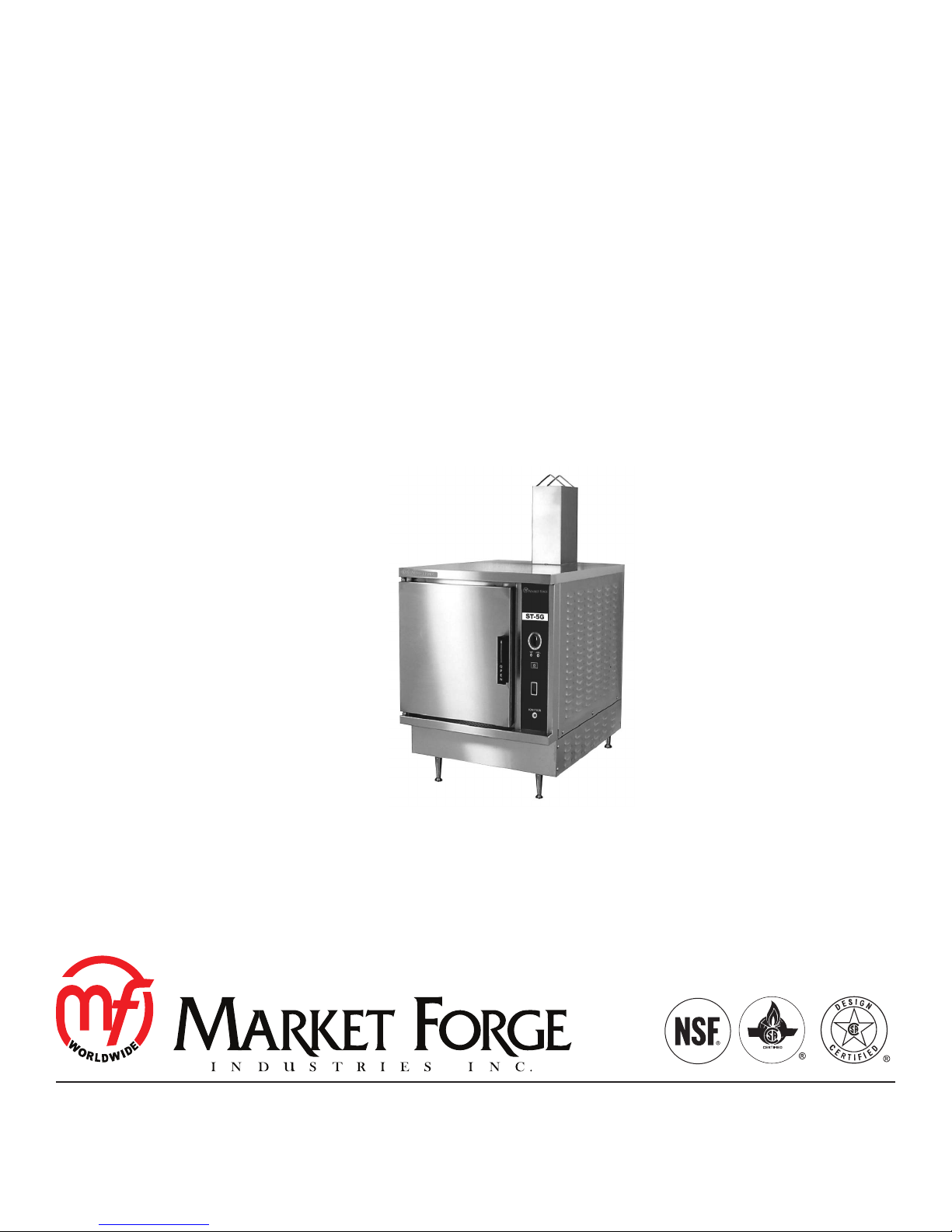
ST-5G
GAS COUNTERTOP CONVECTION STEAMER
INSTALLATION - OPERATION - MAINTENANCE
44 Lakeside Avenue, Burlington, Vermont 05401 USA
Telephone: (802) 658-6600 Fax: (802)864-0183
www.mi.com PN 14-0265 Rev A (7/14)
© 2014 - Market Forge Industries Inc.
Page 2

Your Service Agency’s Address:
Model
Serial number
Oven installed by
Installation checked by
Page 3

IMPORTANT
TABLE OF CONTENTS
WARNING: Improper installation, adjustment, alternation,
service or maintenance can
cause property damage, injury or death. Read the installation, operation and maintenance instructions thoroughly
before installing or servicing
this equipment.
INSTRUCTIONS TO BE FOLLOWED IN THE EVENT THE
USER SMELLS GAS MUST BE
POSTED IN A PROMINENT LOCATION. This information may
be obtained by contacting your
local gas supplier.
FOR YOUR SAFETY
Do not store or use gasoline or
other ammable vapors or liquids in the vicinity of this or any
other appliance.
INSTALLATION
Introduction .............................................................. 2
Service Connections ..................................................... 3
Location and Installation .................................................. 4
Utility Connections ....................................................... 5
Performance Check .................................................. 6
OPERATION
Control Panel ............................................................ 7
Steamer Operation ....................................................... 8
Steam Cooking .......................................................... 9
Suggested Steam Times ................................................. 10
MAINTENANCE
Cleaning & Deliming ...................................................... 1
The information contained in this
manual is important for the proper installation, use, and maintenance of this oven. Adherence
to these procedures and instructions will result in satisfactory
baking results and long, trouble free service. Please read
this manual carefully and retain
it for future reference.
ERRORS: Descriptive, typographic or pictorial errors are
subject to correction. Specications are subject to change
without notice.
Page 4

Introduction
DESCRIPTION
The ST-5G is a gas red countertop pressureless cooker.
The cooking compartment is equipped with a three-piece
door with inner gasket plate isolated from the exterior surface. Door latch operates by action for positive sealing on
inner door. Operation controls are displayed on a frontmounted panel and included timer with indicator lights for
selection of constant steam or selectable timed cooking.
The unit is equipped with a gas red, stainless steel generator operating at 0 PSI and rated at 45,000 BTU.
BASIC FUNCTIONING
The cooker becomes operational when it is set to constant steam, or the timer is set at the desired cooking time
and the compartment door is closed.
At the end of the set interval, timer contact switch to shut
off the cooking operation and sound a signal buzzer. The
buzzer is silences by returning the timer dial to the OFF
position. In the constant steam mode, cooking operation
will be continuous.
Steam emitted from the compartment along with liquid
cooking drainage is directed through a drain screen inside
the compartment into the cooker drain line to the generator drain box. A cold water condenser in the rear of the
cooking chamber helps to condense the steam prior to
discharge into the drain.
The steamer freely vents itself by the negative pressure
created by the condensate water drainage. This negative
pressure prevents steam leakage around the door gasket
and helps draw steam though the cooking compartment.
Steam leakage at the door may indicate a plugged or improperly installed drain screen.
SERVICE
Should repairs be required, a network of Authorized
Agencies is available to assist with prompt service. A
current Directory of Authorized Service Agencies may be
obtained by contacting:
Market Forge Industries, Inc.
44 Lakeside Avenue, Burlington, VT 05401 USA
Tel: (802) 658-6600 • Fax: (802) 864-0183
www.mi.com
The Model and Serial Numbers must be referenced
when corresponding with Market Forge. The data plate
containing the serial number is located on the top front of
the steamer (body panel).
CAUTION
Must read before installation
INSTALLATION CODES AND STANDARDS:
Gas installation to conform local codes, or in absence
of local codes, with the National Fuel Gas Codes - ANSI
ZZ223.1/NFPA 54. In Canada installation to be in accordance with the Natural Gas and Propane installation
code, CSA B149.1 and/or local codes.
• The unit and its individual shut off valve must be disconnected from the gas supply piping system during
any pressure testing of that system at pressures in
excess of 1/2 PSI.
• The unit must be isolates from the gas supply system by closing its individual manual shut off valve
during any pressure testing of the gas supply piping
system at test pressures equal to or less then 1/2
PSI.
Electrical Grounding must be provided in accordance with
local codes, or in the absence of local codes, with the
National Electric Code ANSI/NFPA 70. In Canada, installation must be in accordance with the Canadian Electrical
Code CSA C22.2.
WARNING
Electrical Grounding Instructions:
Units come equipped with a three prong
(grounding) plug for your protection against
shock hazard and should be plugged directly
into a properly grounded three prong receptacle. DO NOT cut or remove the ground prong
from this plug (120 volt units only).
NOTE: WIRING DIAGRAM FOR THIS UNIT IS LOCAT-
ED ON THE RIGHT HAND SIDE PANEL OF THE
COOKER CABINET.
MECHANICAL CONNECTIONS:
The pressureless cooker is interconnected at the factory
to the steam boiler. All electrical and plumbing connections are located on the rear panel of the cabinet.
INSTALLATION
2
Page 5
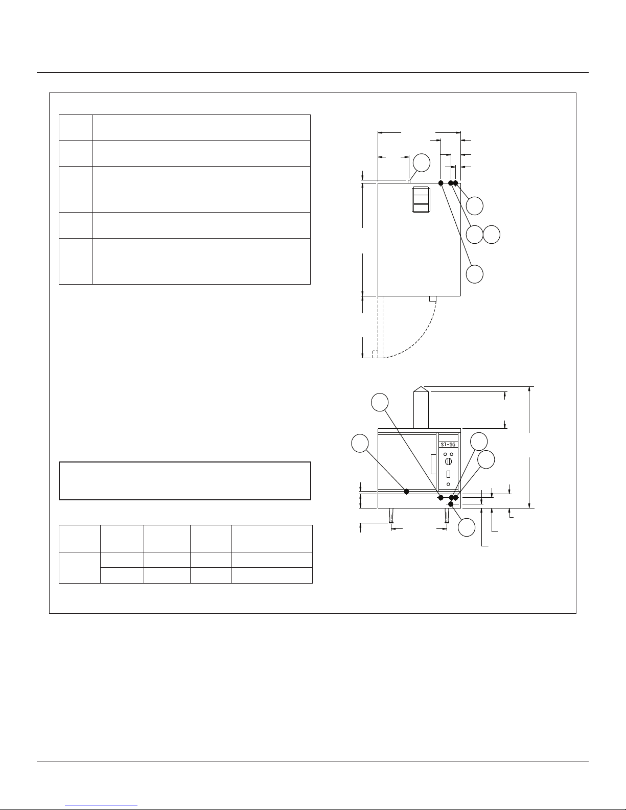
SERVICE CONNECTIONS
G Gas Connection - 3/4” (19mm) IPD O.D. supply line
required.
GW Generator Water - 3/8” (10mm) O.D. tubing at 25-50 PSI
(1.8-3.5kg/cm2)
E Electrical Connection - Unless otherwise specified, field
wire electrical connection to be 120 Volts, 60 Hz and 1pH
with grounding wire. Furnished with 6’ cord and 3 prong
plug. Maximum Amps 2.0.
CW Condensing Water - 3/8” (10mm) O.D. tubing at 25-50
PSI (1.8-3.5kg/cm2)
D Drain - 1” (25mm) IPS O.D. piped to open floor drain.
DO NOT MAKE SOLID CONNECTION TO THE FLOOR.
24” length before open air gap opening. NO BENDS OR
ELBOWS.
WATER QUALITY STATEMENT
Water quality is a major factor affecting the performance of your
appliance. If you are unsure of water quality, consult your local water
treatment specialist and have the water analyzed. Your water supply
must be within these general guidelines:
Total Dissolved Solids
Total Alkalinity
Silica
Chlorine
pH Factor
Water which fails to meet these standards should be treated by
installation of water conditioner.
FAILURE OR MALFUNCTION OF THIS APPLIANCE DUE
TO POOR WATER QUALITY IS NOT COVERED UNDER
WARRANTY.
1.12
[29]
32
[813]
16.75
[425]
D
1
[25]
E
9
[299]
24 [610]
D
Service Connections
5.25 [133]
3 [76]
1.75 [44]
CW
G
GW
E
12
[305]
GW
CW
40.38
[1026]
GAS REQUIREMENTS
MODEL FUEL BUT/HR. kW/HR.
ST-5G
Natural 45,000 13.2 Min. 4” (120mm)
Propane 45,000 13.2 Min. 11” (279mm)
WATER COLUMN
PRESSURE
Figure 1
3
4 [102] MIN.
16 [406] G
DIMENSIONS ARE IN INCHES [MM]
5 [127]
4 [102]
1.75 [44]
INSTALLATION
Page 6

Location and Installation
The location of installation must be under an exhaust
hood, which will remove water vapor emitted when the
cooker door is opened, and exhaust fumes. Level the
unit in nal location by turning adjustable feet. Using the
cabinet top as a reference, obtain level adjustment from
left-to-right and front-to-back.
Exhaust Fans and Canopies
Canopies are set over ranges, ovens, kettles, etc., for
ventilation purposes. It is recommended that a canopy
extend 6” past appliance and be located 6’ - 6” from the
oor. Filters should be installed at an angle of 45O or
more with the horizontal. This position prevents dripping
of grease and facilitates collecting the run-off grease in
adrippan, usually installed with the lter. A strong exhaust
fan tends to create a vacuum in the room and may interfere with burner performance or may extinguish pilot
ames. Makeup air openings approximately equal to the
fan area will relieve such vacuum. In case of unsatisfactory performance on any appliance; check with the exhaust
fan in the “OFF” position.
Wall Exhaust Fans
The exhaust fan should be installed at least two feet
above the vent opening at the top of the unit.
INSTALLATION
WARNING
These procedures must be followed by quali-
ed personnel or warranty will be voided. An
open gap oor drain is required immediately
below the appliance drain.
To Install:
1. Uncrate carefully. Report any hidden freight damage
to the freight company immediately.
2. Set the unit in place. Be certain to maintain the minimum clearances from combustibles and non-combustibles.
3. Level appliance using spirit level. Should anged ad-
justable feet be provided, anchor to oor using proper
anchoring devices.
4. Seal bolts and anged feet with Silastic or other
equivalent compound.
5. Be certain to leave adequate clearances for cleaning,
maintenance and service.
CLEARANCES
Adequate clearance must be provided in aisle and at the
side and back. Adequate clearances for air openings into
the combustion chamber must be provided, as well as for
serviceability for use on noncombustible oors. Minimum
clearance from combustible and noncombustible construction, 3” on left side, 8” on right side and 6” from back.
INSTALLATION
4
Page 7

Utility Connections
GAS CONNECTION
1. The serial and rating plate on the unit indicates the
type of gas your unit is equipped to burn. DO NOT
CONNECT to any other gas types than the type spec-
ied.
2. A 3/4” NPT line is provided at rear for the connection.
Each compartment is equipped with an internal press
regulator which is set at 3.5” WC manifold pressure
for natural gas and 10” WC for propane gas. Use 1/8”
pipe tap n the burner manifold for checking pressure.
An adequate gas supply is imperative. Undersized or low
pressure lines will restrict the volume of gas required for
satisfactory performance. A stead supply of pressure, between 6” WC and 14” WC, for natural gas and between
11” WC and 14” WC for propane gas is recommended.
With all units operating simultaneously the manifold pressure on all units should not show any appreciable drop.
Fluctuations of more that 25% on natural gas and 10% on
propane gas will create problems, affecting burner operation. Contact you local gas company for correct supply
line sizes.
Purge the supply line to clean out any dust, dirt or other
foreign matter before connecting the line to the unit. Use
pipe joint compound which is suitable for use with propane on all threaded connections. A manual gas shut-off
valve for each compartment is supplied with the unit.
Test pipe connections thoroughly for gas leaks.
All the connections must be checked for leaks, after the
unit has been put in operation. Use soapy water only for
testing on all gases. Never use an open ame to check
for gas leaks.
PLUMBING CONNECTION
WARNING
PLUMBING CONNECTIONS MUST COMPLY WITH
APPLICABLE SANITARY, SAFETY AND PLUMBING
CODES.
Two water lines are provided, one for each compartment. Connect water supply line to the 3/8” copper tube
in at the rear of the steamer. The 3/8” copper tube supplies water to both the generator tank and condense live
steam enter the drain line.
DRAIN CONNECTION
The drain connection must be 1” IPS vertically down,
preferably with one elbow only, and maximum length of 6
feet, piped to an open air gap type drain.
ELECTRICAL CONNECTION
WARNING
DO NOT CONNECT THE UNIT TO THE ELECTRICAL SUPPLY UNIT AFTER GAS CONNECTION HAS BEEN MADE.
120 VAC / 60 Hz / 1pH: Units with this rating are factory
supplied with a three-wire cord and three-prong plug
which ts any standard 120V, three-prong receptacle. A
separate 15 amp supply is needed for each unit.
Figure 2
CAUTION
PVC or CPVC are not acceptable materials for
drains.
In order to avoid any back pressure in the
steamer, DO NOT connect solidly to any drain
connection.
5
INSTALLATION
Page 8

Utility Connections
COLD WATER CONDENSER
The steamer is equipped with a cold water condenser in
the rear of the cooking chamber which helps to condense
the steam prior to discharge into drain.
The steamer freely vents itself by the negative pressure
created by the condensate water drainage. This negative
pressure prevents steam leakage around the door gasket
and helps draw the steam through the cooking compartment. Steam leakage at the door may indicate a plugged
or improper installed drain.
WATER CONDITIONING
It is important that the water supply connected to this
steamer be softened to no more than 2.0 grains of hardness and have a pH of 6 to 7.5. This degree of hardness
can be easily obtained with the use of a properly maintained water softener. The use of a water meter eill determine the water consumption and when the water softener
needs regeneration or recharging. Failure to comply with
these water condition standards may void the warranty.
Untreated water contains scale producing minerals which
can precipitate onto the surface in the boiler. Due to the
temperatures in the boiler, the minerals can bake onto the
surface and components. This can result in early component failure and reduced product life.
Water level probes become coated with scale. Scale will
bridge across the probe insulator from the metal extension which senses the water level in the boiler shell. Once
this scale becomes wet, the water level control is unable
to maintain the proper water level in the boiler. STRAINERS and FILTERS will NOT remove minerals from the
water.
PERFORMANCE CHECK
Once the steamer is installed and all mechanical connections have been made, thoroughly test the steamer before
operation.
1. Check that proper water, drain, electrical and gas
connections have been made.
2. Turn main power switch ON. After approximately 19
minutes the READY light should come on, indicating
that the water temperature is 205°F (97°C).
3. Check that IGNITION light comes on and cycles ON
and OFF.
4. When the READY light comes on, set timer to the
5 MINUTE position. With door open, observe that
no steam is entering the compartment and that the
COOKING light is OFF.
5. Close the compartment door. The COOKING light
should now be ON and steam should be heard entering the compartment after about 45 seconds.
6. Ensure that water from cold water condenser is owing through the drain line.
7. Open compartment door and observe that steam supply to chamber is cut off. READY light should come
ON again as COOKING light goes OFF.
8. Close compartment door and let cooking cycle nish. When the timer returns to 0 position, a buzzer will
sound signaling the end of the cooking cycle. Buzzer
must be manually turned off by setting the timer to its
OFF position.
INSTALLATION
6
Page 9

Control Panel
1. IGNITION LIGHT - When lit, indicates burners have
been ignited and are heating the generator tank.
2. READY - PILOT LIGHT: When lit, indicates
steam chamber has reached 205oF (97oC) and is
ready for the cooking cycle.
3. COOKING PILOT LIGHT - When lit, indicates that
cooking cycle is in progress.
4. TIMER - Set the cooking timer (0 to 60 minutes) Steam cooking will begin when the door is closed.
The cooking cycle will be interrupted if the door is
open during the cooking cycle; resume cooking by
closing the door.
5. MAIN POWER SWITCH:
ON - The boiler will automatically ll and begin heating to the pre-set temperature. Red
OFF: - The boiler will drain. No lights.
DELIME GENERTOR LIGHT (IF EQUIPPED) - Indicates that lime scale deposits have accumulated in
the steam generator and that a DELIME procedure
should be performed at the next convenient opportunity.
6. BUZZER - Signals end of cooking period (not shown).
Figure 3
7
OPERATION
Page 10

Steamer Operation
WARNING
The steamer and its parts are hot. Use care
when operating, cleaning or servicing the
steamer. The cooking compartment contains
line steam. Stay clear when opening door.
Your steamer has been factory set when ON to maintain
water temperature during the READY pH at approximately 205°F (97°C) just below water boiling point.
WARNING
IN THE EVENT OF MAIN POWER BURNER
IGNITION FAILURE, A 5 MINUTE PURGE
PERIOD MUST BE OBSERVED PRIOR TO
RE-ESTABLISHING IGNITION SOURCE. IF SO
EQUIPPED, SOME UNITS WILL AUTOMATICALLY RE-ATTEMPT IGNITION.
WARNING
IN THE EVENT THE USER SMELLS GAS
SHALL BE POSTED IN A PROMINENT LOCATION. THIS INFORMATION SHALL BE OBTAINED BY CONSULTING THE LOCAL GAS
SUPPLIER.
LIGHTING
1. Ensure power, gas and water supply is on.
2. Turn POWER switch ON.
3. Generator tank will begin lling with water.
COOKING
Before loading the cooker, be sure the compartment is hot
(Refer to preheating instructions above).
1. Slide pans of food into cooking compartment pan
supports.
2. Close cooking compartment door.
3. Set timer cooking time.
4. Set timer to the required cooking time (Refer to cook-
ing guidelines).
a. Constant Steam - For continuous cooking.
b. 60 Minute Timer - For timed cooking.
5. Turn off buzzer when cooking cycle is complete, by
turning the timer dial to the “off “ position.
6. Open door slightly at rst letting most of the steam
out of the compartment and then fully open the door.
7. Unload by sliding pans of food from pan supports.
SHUTDOWN
NOTE: The cooking compartments are operated indepen-
dently of each other. Each has its own gas, water
supply and generator tank.
STAND BY
1. Set timer to OFF position and leave door slightly
open.
4. Once water level has been reached, the IGNITION
light should come on and remain on until READY light
comes on.
5. Steamer is now ready for use.
PREHEATING
Before each initial operation of cooking and at any other
time when the cooking compartment is cold a 1 minute
preheating period is required. To preheat the cooker put
steam source into operation and proceed as follows:
1. Close cooking compartment door.
2. Set 60 minute timer dial to “1 minute” setting.
3. Turn off buzzer, which sounds to indicate cooking is
complete, by setting the timer dial to the “off ” position.
OPERATION
COMPLETE SHUTDOWN
1. Set timer to OFF and turn POWER switch to OFF.
Generator will drain automatically.
2. Turn water supply OFF.
3. Turn gas supply OFF.
4. Disconnect power supply.
8
Page 11

Steam Cooking
Your steamer efciently cooks vegetables or other foods
for immediate serving. Steam cooking should be carefully timed and controlled. Keep hot food holding time to
a minimum to produce the most appetizing results. Prepare small batches, cook only enough to start serving,
then cook additional amounts to meet demand. Separate
frozen foods into smelled pieces to allow more efcient
cooking.
Use a pan cover for pre-cooked frozen dishes that cannot
be cooked in the covered containers in which they are
packed if they require more than 15 minutes of cooking
time. When cover is used approximately one-third additional cooking time is necessary.
Cooking frozen foods depends on amount of defrosting
is required. If time permits, allow frozen foods to partially
thaw overnight in the refrigerator. This will reduce their
cooking time.
PREPARATION
Prepare vegetables, fruits, meats, seafood and poultry normally by cleaning, separating, cutting, removing
stems, etc. Cook root vegetables in a perforated pan un-
less juices are being saved. Liquids can be collected in a
solid 12” x 20” pan placed under a perforated pan. Perforated pans are used for frankfurters, wieners and simulate items when juices do not need to be preserved. Solid
pans are good for cooking puddings, rice and hot breakfast cereals. Vegetables and fruits are cooked in solid
pans in their own juices. Meats and poultry are cooked in
solid pans to preserve their own juices to to retain broth.
Canned foods can be heated in their opened cans placed
in the pans or the contents may be poured into solid pans.
PANS
The steamer compartment is designed to accept combinations of the pan of 12” x 20” (solid or perforated) as
shown in the table below:
DEPTH OF PAN NUMBER OF PANS
1” 10
2.5” 5
4” 3
6” 2
FACTS ON PARADE
1. Frozen vegetables should always be cooked in perforated 12” x 20” x 2.5” pan. 7.5lbs. (34kg) maximum
per pan.
2. Frozen entrees should be underlined with a perforated pan for best results. If they are defrosted before
hand, the heating time will be decreased.
3. Fresh foods may also be cooked in this unit. When
the stock is not to be retained should be cooked in
perforated 12” x 20” x 2.5” pans for the most nutritious
results.
4. There is a safety micro-switch on the door which
shuts off the steam each time the door is opened if
the unit is in the cooking cycle.
5. Total cooking time will vary depending on the load,
even though the timer setting is the same.
6. All foods, except cakes and pastry, can be coked in a
steam cooking unit.
7. Steam cooked meals have greater nutritional value
since they retain most of their vitamins and minerals.
8. Because foods are cooked faster by the higher temperatures of steam cooking, they can be prepared
closer to serving time, insuring maximum freshness.
9. Steam cooked foods have a higher percent yield
more portions per dollar spent.
10. Food may be served from the same pan in which it
is steam cooked, thus reducing food breakage since
there is no extra handling of transferring of food from
cooking pans to serving pans. It also reduces pot
washing tasks.
11. Some important advantages of steam coking are labor saving, reduced operating costs, space saving
and the lifting of heavy stock pots is eliminated.
12. Rice and spaghetti products, it thoroughly wet at the
start of the cooking process are very easily prepared.
13. Food such as potatoes, poultry, seafood and some
meats may be blanched in the steam cooker, thus reducing the total cooking time and grease absorption.
14. The steam cooker will loosen foods on pans making
washing easier.
15. Solid pans are recommended when liquid is to be re-
tained and perforated pand when the liquid is not to
be retained.
16. Eggs may be cooked out of the shell if they are to be
chopped which eliminates peeling after steaming.
17. The steam cooker can be opened during the cooking
period to add or remove items.
18. Steam cooking information including recommended
pan size and type, weight per pan, cooking times and
pan yields are given on the next few pages of this
bulletin.
9
OPERATION
Page 12

Suggested Steam Times
HEIGHT OF
WEIGHT
ITEM
VEGETABLES
Beans, Snap Green or
Waxed
Beets, 2” Diameter 7.5 lbs. (3.5kg) 2.5” (65mm) 1-3 40-50
Broccoli 1/2-3/4”, Stalks 6 lbs. (2.7kg) 2.5” (65mm) 1-3 14-18
Carrots, Sliced 9 lbs. (4kg) 2.5” (65mm) 1-3 18-21
Cauliower, Trimmed,
1.5”-2”
Corn on Cob, Husked 1 doz. 2.5” (65mm) 1-3 10-15 12
Cabbage 1/4-1/6 of Head,
Cored
Onions, 2” Diameter 6 lbs. (2.7kg) 2.5” (65mm) 1-3 20-25
Peas, Shelled 5 lbs. (2.25kg) 2.5” (65mm) 1-3 5-6
Potatoes, French Fry Cut 10 lbs. (4.5kg) 2.5” (65mm) 1-3 18-21
Potatoes, Regular Cut, 3” 10 lbs. (4.5kg) 2.5” (65mm) 1-3 35-40
Spinach, Cleaned Cut 3 lbs. (1.4kg) 2.5” (65mm) 1-3 3-5
Squash, Summer, Sliced
1” Thick
Squash, Winter, Peeled 9 lbs. (4kg) 2.5” (65mm) 1-3 10-15
Turnip, Diced 5 lbs. (2.25kg) 2.5” (65mm) 1-3 28-32
FROZEN VEGETABLES
Asparagus, Spears 7.5 lbs. (3.4kg) 2.5” (65mm) 1-3 12-15
Beans, Green, Regular 6 lbs. (2.7kg) 2.5” (65mm) 1-3 10-15
Beans, Green, French Cut 6 lbs. (2.7kg) 2.5” (65mm) 1-3 5-7
Beans, Lima
Broccoli
PER PAN
6 lbs. (2.7kg) 2.5” (65mm) 1-3 18-22
6 lbs. (2.7kg) 2.5” (65mm) 1-3 12-16
5 lbs. (2.25kg) 2.5” (65mm) 1-3 14-18
7 lbs. (3.2kg) 2.5” (65mm) 1-3 7-10
7.5 lbs. (3.4kg) 2.5” (65mm) 1-3 12-15
6 lbs. (2.7kg) 2.5” (65mm) 1-3 4-6
12” x 20”
PERFORATED
NUMBER
OF PANS
TIMER
SETTINGS
IN MINUTES
COOKED
SERVINGS
PER PAN
25-30
30 oz. 85g
30-35
3 oz. 85g
25-30
3 o. 85g
45-40
3 oz. 85g
30-35
3 oz. 85g
15-20
4 oz. 115g
25-30
4 oz. 115g
25-30
3 oz. 85g
50
3 oz. 85g
50
3 oz. 85g
10-12
3.75 oz. 105g
30-35
3 oz. 85g
25-30
3 oz. 85g
20-25
4 oz. 115g
30
3 oz. 85g
25
3 oz. 85g
25
3 oz. 85g
30
3 oz. 85g
25
3 oz. 85g
OPERATION
10
Page 13

Suggested Steam Times
HEIGHT OF
WEIGHT
ITEM
Brussel, Sprouts
Carrots
Cauliower
Corn-Cut
Mixed Vegetables 7.5 lbs. (3.4kg) 2.5” (65mm) 1-3 8-12
Peas, Loose 7.5 lbs. (3.4kg) 2.5” (65mm) 1-3 3-5
Spinach 9 lbs. (4kg) 2.5” (65mm) 1-3
Squash 12 lbs. (5.4kg) 2.5” (65mm) 1-3
FROZEN PREPARED ENTREES
Lobster Tails, 6-8 oz. 7-8 lbs. (3.2-3.6kg) 2.5” (65mm) 1-3 15-25
Shrimp, C.D.P. 16-20 lbs. (7-9kg) 2.5” (65mm) 1-3 8-11
Shrimp, Raw 16-20 lbs. (7-9kg) 2.5” (65mm) 1-3 11-15
Bulk Pack, Frozen
Bulk Pack, Defrosted
CANNED VEGETABLES
Vegetables, Canned 7 lbs. (3.2kg) 2.5” (65mm) 1-3 5-10
PER PAN
7.5 lbs. (3.4kg) 2.5” (65mm) 1-3 10-15
6 lbs. (2.7kg) 2.5” (65mm) 1-3 10-15
7.5 lbs. (3.4kg) 2.5” (65mm) 1-3 7-12
7.5 lbs. (3.4kg) 2.5” (65mm) 1-3 8-12
3.5-4 lbs
(1.6-1.8kg)
3.5-4 lbs.
(1.6-1.8kg)
12” x 20”
PERFORATED
2.5” (65mm) 1-3 11-15
2.5” (65mm) 1-3 25-35
NUMBER
OF PANS
TIMER
SETTINGS
IN MINUTES
Must be
defrosted
Must be
defrosted
COOKED
SERVINGS
PER PAN
30
3 oz. 85g
25
3 oz. 85g
25
3 oz. 85g
30
3 oz. 85g
30
3 oz. 85g
30
3 oz. 85g
30
4 oz. 115g
50
3 oz. 85g
15
6 oz. 170g
75
3 oz. 85g
50
3 oz. 85g
10
6 oz. 170g
10
6 oz. 170g
25-30
3 oz. 85g
MISCELLANEOUS
Eggs, in Shell 3 doz. 2.5” (65mm) 1-3 9-11
Eggs, out of Shell 4 doz. 2.5” (65mm) 1-3 6-8
Rice 4 lbs. (1.8kg) 2.5” (65mm) 1-2 18-22
Spaghetti 3 lbs. (1.4kg) 4” (102mm) 1-2 18-22
11
36
1 Egg Each
48
1 Egg Each
60-65
3 oz. 85g
40-45
4 oz. 115g
OPERATION
Page 14

Suggested Steam Times
HEIGHT OF
WEIGHT
ITEM
MEAT-POULTRY-FISH
Chicken, Cut up 8 lbs. (3.64kg) 2.5” (65mm) 1-3 20-30
Chicken, 4 lbs., Whole 3 Each 4” (102mm) 1-3 45-50
Fowl, 5 lbs. or more,
Whole
Fish, Fillets 3 lbs. (1.4kg) 2.5” (65mm) 1-3 10-15
Frankfort 5 lbs. (2.3kg) 2.5” (65mm) 1-3 3-5
Hamburgers, 3 oz. 5 lbs. (2.3kg) 2.5” (65mm) 1-3 18-22
Meatballs, 1 oz. * 6 lbs. (2.7kg) 2.5” (65mm) 1-3 20-25
Meatloaf * 15 lbs. (6.8kg) 2.5” (65mm) 1-3 40-50
Pork Chops, 4 oz., Loin
Bone
Sausage, 1.5 oz. 6 lbs. (2.7kg) 2.5” (65mm) 1-3 18-21
Turkey, on Carcass 20-22 lbs. (9-10kg) 2.5” (65mm) 1 2-2.5 Hours
* Raw weight for meatballs and meatloaf includes hamburger and extenders and yiels 2 oz. protein plus extenders or 3 oz.
total portion.
PER PAN
2 Each 4” (102mm) 1-3 50-60
6 lbs. (2.7kg) 2.5” (65mm) 1-3 25-30
12” x 20”
PERFORATED
NUMBER
OF PANS
TIMER
SETTINGS
IN MINUTES
COOKED
SERVINGS
PER PAN
15-20
2 oz. 55g
25-30
2 oz. 55g
20-25
2 oz. 55g
12-15
2 oz. 55g
35-40
2 oz. 55g
20-25
2 oz. 55g
20-25
2 oz. 55g
50-60
2 oz. 55g
24
2 oz. 55g
18-20
2 oz. 55g
50-65
2 oz. 55g
OPERATION
12
Page 15

NOTICE
As a safety precaution, disconnect the power
supply during cleaning or servicing.
CLEANING DAILY
Cleaning at the end of each day, or between cooking cycles if necessary:
1. Turn main POWER switch OFF.
2. Remove pans and racks from compartment and was
in sink.
3. Wash compartment interior with clean water.
4. Use warm soapy water with a cloth or sponge to clean
exposed bead of door gasket, rinse with warm clear
water and wipe with a dry cloth. Do not apply food oils
or petroleum solvents or lubricants directly to the door
gasket or surfaces which touch the door gasket.
5. Remove drain screens from inside compartment
drains. Using a plastic bottle brush and mild detergent, clean inside the drain opening ensuring there is
no food residue or blockage. Clean the drain screen
and replace in its original position.
6. Leave door slightly open when steamer is not in use.
CAUTION
DO NOT USE CLEANING AGENTS THAT ARE
CORROSIVE!
NOTE: Contact the factory, the factory representative or
local service company to preform maintenance
and repairs should the unit malfunction. Refer to
warranty terms and conditions.
WEEKLY CLEANING
1. Clean exterior with a damp cloth and polish with a soft
dry cloth.
2. Use a non-abrasive cleaner to remove discolorations.
3. Clean around burner air mixer and orice if lint has
accumulated. Side cover must be removed to clean
this area.
Cleaning & Deliming
MONTHLY CLEANING
1. Clean around burner air mixers, louvered panels if
grease or lint has accumulated.
NOTE: Following daily and period maintenance proce-
dures will enhance long-life for your equipment.
Climatic conditions, such as salt air may require
more thorough and frequent cleaning, otherwise
the life of the equipment could be adversely affected.
NOTE: Use of cleaning agents that contain chloride, ac-
ids or salts which are corrosive may cause pitting
and corrosion when used over a period of time;
this will reduce the life of the unit. Should pitting or
corrosion occur, this is not covered by warranty.
Follow the recommend cleaning instructions. Use
a mild detergent, warm water and rinse thoroughly.
WARNING
NEVER SPRAY WATER INTO ELECTRIC CONTROLS!
STAINLESS STEEL
To remove normal dirt, grease or product residue from
stainless steel, use ordinary soap and water (with or without detergent) applied with a sponge or cloth. Dry thoroughly with a clean cloth. Never use vinegar or any corrosive cleaner.
To remove grease and food splatters or condensed va-
pors that have baked on the equipment, apply cleanser
to a damp cloth or sponge and rub cleanser on the metal
in the direction of the polishing lines on the metal. Rubbing cleanser as gently as possible in the direction of the
polished lines will not mar the nish of the stainless steel.
NEVER RUB WITH A CIRCULAR MOTION.
Soil and burnt deposits which do not respond to the above
procedure can usually be removed by rubbing the surface with SCOTCH - BRITE scouring pads or STAINLESS
scouring pads. DO NOT USE ORDINARY STEEL WOOL
as any particles left on the surface will rust and further
spoil the appearance of the nish. NEVER USE A WIRE
BRUSH, STEEL SCOURING PADS (EXCEPT STAINLESS), SCRAPPER, FILE OR OTHER STEEL TOOLS.
Surfaces which are marred collect dirt more rapidly and
become more difcult to clean. Marring also increases
the possibility of corrosive attack. Renishing may then
be required.
13
MAINTENANCE
Page 16

Cleaning & Deliming
TO REMOVE HEAT TINT:
Darkened areas sometimes appear on the stainless steel
surface where the area has been subjected to excessive
heat. These darkened areas are caused by thickening of
the protective surface of the stainless steel and are not
harmful. Heat tint can normally be removed by the foregoing, but tint which does not respond to this procedure calls
for a vigorous scouring in the direction of the polish lines
using SCOTCH - BRITE scouring pads or a STAINLESS
scouring pad in combination with a powdered cleanser.
Heat tint action may be lessened by not applying or by
reducing heat to equipment during slack periods.
REMOVAL OF SCALE DEPOSITS
It is recommended that your steamer be delimed once a
month, or more often if necessary.
Should your steamer develop a heavy build-up of lime
scale deposits, use the CLR TREATMENT KIT available
from your authorized servicer.
Before beginning deliming procedures, ensure that the
water is not overowing into the cooking compartment.
DELIMING PROCEDURE:
For Units Equipped with the Feature:
WARNING
READ THE FOLLOWING IN INSTRUCTIONS ON THE
CLR BOTTLE. USE PLASTIC OR RUBBER GLOVES
TO AVOID SKIN CONTACT. IF CLR COMES IN CONTACT WITH SKIN, RINSE WITH CLEAN WATER.
2. Drain steam generator by setting POWER switch to
OFF, set cooking timer to 0.
3. Turn POWER switch to DELIME.
4. Unscrew brass deliming plug on right side of steamer.
5. Insert hose in hole of port.
6. Pour 20 ounces of solution into generator slowly to
avoid spillage.
7. Remove hose. Screw deliming plug back so it seals
tightly.
8. Turn POWER switch on. NOTE: If there is no deliming
plug on the side of the steamer, check with your local
service agency for proper deliming instructions.
9. Allow steamer to remain in ready cycle for 1/2 hour,
then turn POWER switch OFF and allow generator
to drain.
10. Flush cycle. Turn POWER switch to ON. When
READY light comes on, switch POWER to OFF. Re-
peat this step until generator is completely ushed
and drained.
11. Clean exterior and interior. (Refer to STAINLESS
STEEL Section above for cleaning instructions). After
the unit is clean leave compartment door open when
not in use.
12. Steamer is now ready for use or turn off for overnight
shutdown.
MAINTENANCE
14
 Loading...