

Market Forge Industries MSA-SB-2600 Owner's Manual

MSA-SB-2600 MILITARY SUB-ASSEMBLY
HIGH EFFICIENCY ELECTRIC CONVECTION OVEN
OWNER’S MANUAL
MODEL:
MSA-SB-2600
•
COVERING:
INSTALLATION
•
OPERATION
•
SERVICE & PARTS
•
NSN: 9Z 7310-01-519-8399
APL: 43A040025
MF P/N: 98-3600 (No Drain)
NSN: TBD
APL: TBD
MF P/N: 98-3660 (Liner Drain)
*It is our policy to build equipment which is design certied by U.L. However, a continuing program of product improvement makes it necessary to submit new models to the agencies as they are developed and consequently not all models bear the appropriate agency labels
at all times.
Form Number: S-4885 D 02/09
Printed in U.S.A. 35 Garvey Street l Everett l MA l 02149
Tel: (617) 387-4100 l Fax: (617) 387-4456 l Outside MA Fax: (800) 227-2659
E-Mail: CUSTSERV@mi.com l Website: www.mi.com

IMPORTANT NOTICE
NOTES:
1) Accutemp griddle mounting;
This version of the Installation Manual for the Market Forge oven model MSASB-2600 includes the (4) parts (listed below) that were modied in order to
accept the Accutemp Griddle being mounted on top. All ovens shipped from
the Market Forge factory with a Serial Number less than #226167 will require
a back t kit, Market Forge part number 98-4162, in order to mount the Accutemp griddle. The back t kit includes the updated version of the (4) parts
listed below and installation instructions. A simple replacement of these (4)
parts with the back t kit parts will allow the griddle to be mounted on top.
The tools required to perform the replacement are a slotted screwdriver and
a 7/16” socket wrench.
List of (4) parts that were modied to accept the Accutemp Griddle;
Part Number Description
98-3571 RIGHT SIDE CHANNEL
98-3572 LEFT SIDE CHANNEL
98-3586 FRONT TOP PANEL
98-3587 REAR TOP PANEL
2) Replacement Reed Switch;
This version of the Installation Manual for the Market Forge oven model
MSA-SB-2600 includes a new part number for the Reed Switch (sometimes
referred to as a Proximity Switch). Due to alignment issues with the original
Reed Switch a new, more forgiving Reed Switch is now being used. The new
Reed Switch part number 08-6615 should be used as a direct replacement
for part number 08-6308 in older model MSA-SB-2600 ovens.
All ovens shipped from the Market Forge factory with a Serial Number less than
#225207 will have the original Reed Switch 08-6308. These can be directly replaced with the new Reed Switch 08-6615.
i

TABLE OF CONTENTS
IMPORTANT NOTICE .......................................................................................................................
Your Energy Efcient Convection Oven ..............................................................................................
How the Oven Operates ....................................................................................................................
Operating Controls and Indicators .....................................................................................................
Operating Instructions ........................................................................................................................
Cleaning/Preventive Maintenance .....................................................................................................
Trouble-Shooting Guide ....................................................................................................................
Illustrated Parts List ............................................................................................................................
Assembly Instructions ........................................................................................................................
Appendix ..........................................................................................................................................
i
ii
ii
1
1
2
2-3
4-6
7-19
20-23
YOUR ENERGY EFFICIENT CONVECTION OVEN
MSA-SB-2600 convection ovens are electrically powered, high
capacity ovens featuring high energy efciency. These ovens
are designed to radically cut power consumption, delivering the
cooking power of a 16 KW oven from only 11 KW’s of energy
input. Improvement of energy use is made possible by a carefully designed insulating system which keeps heat inside the
oven longer.
A convector fan distributes heat uniformly throughout the oven
interior, for fast even roasting and baking.
Like all Market Forge products, MSA-SB-2600 ovens are built
to the highest standards of workmanship, employing only the
HOW THE OVEN OPERATES
MSA-SB-2600 ovens operate by use of two simple controls, a
power switch for turning on the fan motor and control circuit,
and a thermostat for setting the oven temperature. The oven is
otherwise automatic. A thermostat maintains oven temperature
by cycling heating elements on and off, with temperature uctuating no more than 20°F from the setting. Uniform distribution
of heat within the oven is assured by continuous operation of a
convector fan.
A 60-minute and Constant Heat timer serves as an aid in using the oven, when the timer expires the heating elements shut
off. To prevent unnecessary loss of heat when the doors are
opened, an interlock switch stops fan operation whenever the
nest materials and components. Of course, Power Saver
II ovens are fully approved by UL, and other ofcial testing
authorities.
right-side door is opened. Should the operator wish to cool
the oven, opening just the left- side door will quickly ventilate
the oven interior.
ii
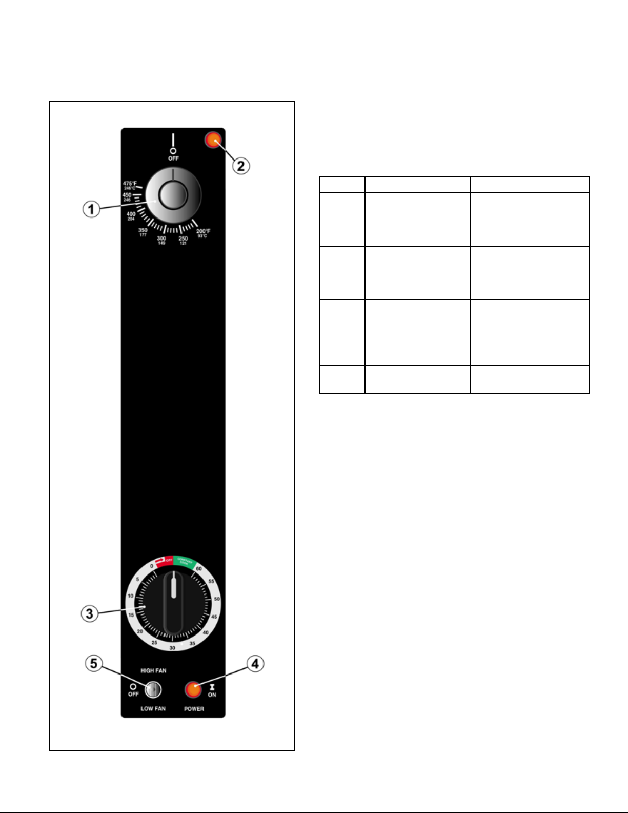
OPERATING CONTROLS & INDICATORS
The controls required to operate the oven are listed in
the following table together with a short functional description of each. The physical location of each control
is shown in FIG.1.
ITEM DESCRIPTION FUCTION
1 Thermostat Control Regulates oven
temperature. Con-
trols heating element
operation.
2 Thermostat Light Indicates when the
thermostat is calling
for heat and the ele-
ments are ON.
3 Timer/Constant
Heat
4 Power Light Indicates power is
Electrical timer to
aid in time cooking
cycles. Controls oven
and constant heat
mode.
ON.
FIG. 1 Operating Controls & Indicators
Check that power is available to the oven
1.
Arrange shelf positions according to the item to be
2.
cooked.
Close doors. Move fan switch to HIGH or LOW.
3.
Fan should come on.
Set thermostat dial to desired cooking temperature.
4.
Element indicator light should come on
Allow oven to preheat for about 5-10 minutes. Pre-
5.
heating is complete when indicator light goes out
and the buzzer sounds. Do not waste energy by
turning the oven on too early.
Load oven. The load should be adjacent to the
6.
oven, so the doors will be open as short a time as
possible.
Close doors. Set timer for desired cooking time.
7.
Buzzer will sound at end of preset interval. Oven is
8.
ready to unload.
If oven temperature is to be lowered, set the ther-
9.
mostat to the desired temperature to cool interior.
Fan will continue to run with left door open and right
door closed. Where indicator light comes on, oven
is at lower temperature. Close left door. When light
goes off, oven is ready for use.
For daily shutdown, place oven thermostat and
10.
power switch in OFF position. For extended shut-
1
CLEANING/PREVENTIVE MAINTENANCE
A good preventive maintenance program in the form of daily cleaning procedures is outlined in the following steps:
Remove oven shelves and wash in mild detergent and water.
1.
Rinse and dry.
Remove left and right hand shelf supports by lifting up and out
2.
toward center of oven. Wash, rinse and dry.
Remove fan bafe by lifting up and out. Wash, rinse and dry.
3.
Wash interior sides, bottom, and top with mild detergent and
4.
water. A stainless steel cleaner (not polish) should be used for
the interior. Rinse and dry.
Replace fan bafe, shelf supports and shelves.
5.
Wash both sides of doors, top & bottom trim using a stainless
6.
steel cleaner. Rinse and dry.
TROUBLE-SHOOTING GUIDE
PROBLEM Probable Cause REMEDY
CONVECTOR FAN FAILS TO OPERATE.
a. Power to oven is off. Locate external circuit breaker for power and place in ON posi-
tion.
b. Power switch off. Place in ON position.
c. Right oven door open. Close Door.
d. Control circuit breaker off. Place in ON position.
e. Faulty circuit breaker, door interlock switch, fan
motor, or wiring.
Refer to wiring diagram or obtain outside service.
INDICATOR LIGHT FAILS TO LIGHT WITH FAN OPERATING, THERMOSTAT SET.
a. Indicator light burned out. Replace light. See service and parts manual for procedure.
b. Electrical failure. Refer to wiring diagram or obtain outside service.
FAN OPERATION - NO HEAT.
a. Thermostat not set. Set thermostat.
b. Faulty contactor, wiring, electrical failure. Refer to wiring diagram or obtain outside service.
2
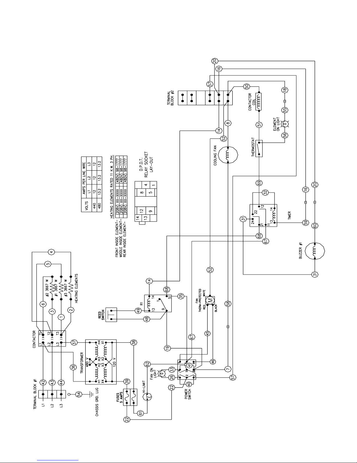
TROUBLE-SHOOTING GUIDE
FIG. 2 Wiring Diagram
3
ILLUSTRATED PARTS LIST
RECOMMENDED SPARE PARTS LIST (P/N 98-3623)
PART NO. DESCRIPTION QTY.
10-7371 SwitchPower/Fan 1
10-5052 Light, Fan Power 1
10-5052 Light, Heating Element 1
08-6615 Reed Switch 1
08-6472 Relay, 120V
08-6475 Relay, Socket
10-4714 Thermostat, 475oF
09-5259 Thermostat, Knob
08-6464 Timer
08-3826 Timer, Knob
10-5944 Contactor
09-7248 Motor, 2 Speed
08-6351 Hi-Limit, Thermostat
08-6468 Fuse, 5Amp
09-6475 Transformer, 500VA
10-7395 Buzzer, 120 Volt
08-7978 Fan, Cooling
98-1777 Element, Heating (480V)
08-6469 Fuse, Holder
1
1
1
1
1
1
1
1
1
2
1
1
1
1
2
4
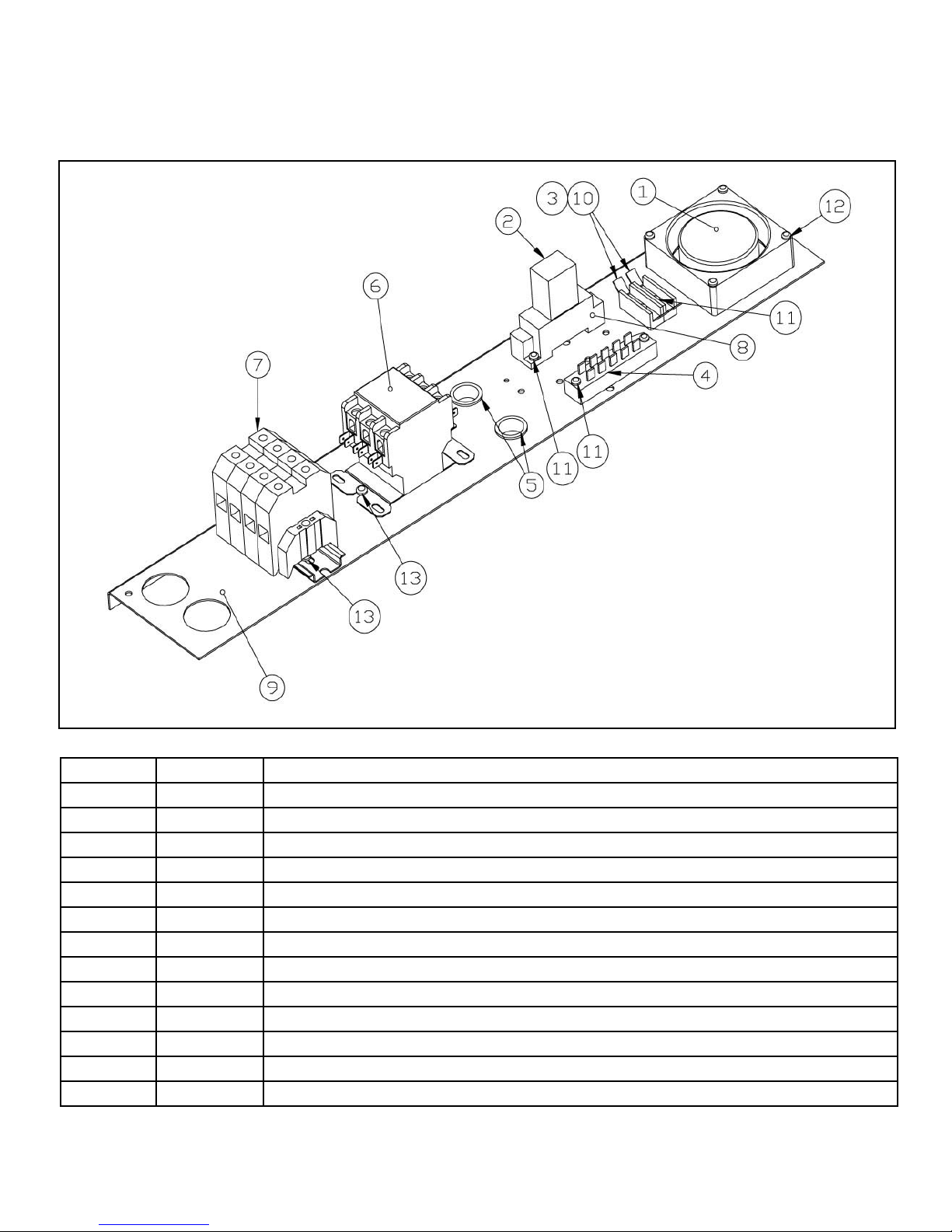
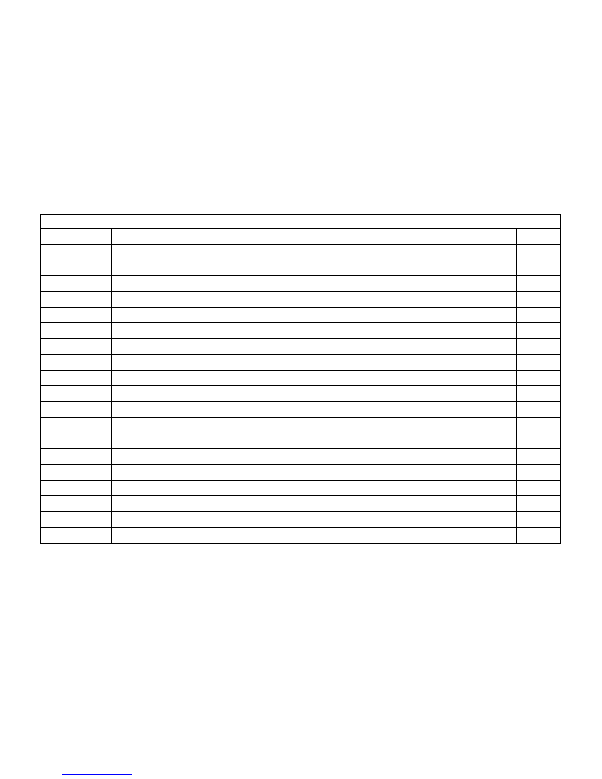
ILLUSTRATED PARTS LIST
FIG. 3 Electric Control Panel with Probe Option
ITEM NO. PART NO. DESCRIPTION
1 08-7978 Fan, Cooling
2 08-6472 Relay, 120 Volts
3 08-6469 Fuse, Holder
4 08-6552 Terminal Strip
5 09-6575 Plug, Hole
6 10-5944 Contactor
7 98-1720 Terminal Block
8 08-6475 Relay, Socket
9 98-3562 Panel, Electric Controls
10 08-6468 Fuse, 5 Amps
11 10-1720 Screw, #6-32 Thread x 1/2” Long, Stainless Steel
12 08-7993 Screw, #6-32 Thread x 1 1/2” Long, Stainless Steel
13 10-1761 Screw, #8-32 Thread x 3/8” Long, Stainless Steel
5
 Loading...