

Page 1
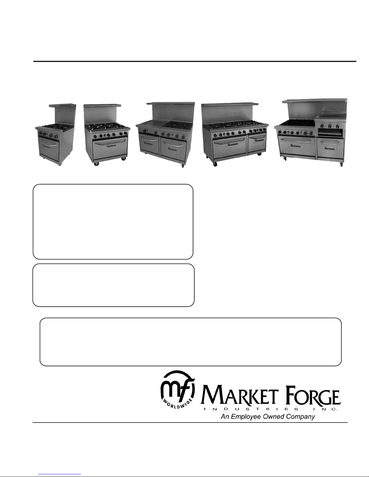
OWNERS MANUAL
INSTALLATION, OPERATION & MAINTENANCE
RANGES & GRIDDLE/BROILER
WARNING:
Improper installation, adjustment,
alteration, service or maintenance can
cause damage, injury or death. Read the
installation, operating & maintenance
instructions thoroughly before installing or
servicing the equipment.
FOR YOUR SAFETY:
Do not store or use gasoline or other
flammable vapors or liquids in the vicinity
of this or any other appliance.
MODELS: m MF-R4
m MF-R6
m MF-R8
m MF-R10
RAISED GRIDDLES:
m MF-RG12-2
m MF-RG12-4
m MF-RG12-6
m MF-RG12-8
m MF-RG24
m MF-RG24-2
m MF-RG24-4
m MF-RG24-6
m MF-RG36-4
COVERING:
- INSTALLATION
- OPERATION
- MAINTENANCE
- PARTS & SERVICE
CAUTION:
Instruction to be followed in the event the user smells gas shall be posted
in a pominent location. This informantion shall be obtained by consulting
the local gas supplier.
Form Number: S-2551
11/04
Printed in U.S.A.
35 Garvey Street l Everett l MA l 02149
Tel: (617) 387-4100 l Fax: (617) 387-4456
Outside Fax: 1-800-227-2659
E-Mail: custserv@mfii.com l Website: www.mfii.com
Page 2

TABLE OF CONTENTS
INSTALLATION INSTRUCTIONS ...................................
RATING PLATE ...............................................................
CLEARANCES ................................................................
HIGH SHELF ASSEMBLY ...............................................
OPERATING INSTRUCTIONS .......................................
LEVELING (RANGES EQUIPED WITH OVENS) ...........
AIR SUPPLY & VENTILATION ........................................
GAS CONNECTION ........................................................
MANUAL SHUT OFF VALVE ...........................................
PRESSURE REGULATOR ..............................................
CONNECTIONS ..............................................................
FLEXIBLE COUPLINGS CONNECTOR & CASTERS ....
INITIAL PILOT LIGHTING ...............................................
TOP BURNERS/RAISED GRIDDLE/BROILER ...............
GRIDDLE .........................................................................
STANDARD OVEN ..........................................................
INTRODUCTION
IMPORTANT:
Installing, Operating and Service Personnel:
Installation of the equipment should be performed
by qualified, certified, licensed and/or
authorized personnel who arc familiar with and
experienced in stale/local installation codes.
1
BEFORE FIRST USE - GRIDDLES ................................
1
BEFORE FIRST USE - OVENS ......................................
1
MAINTENANCE INSTRUCTIONS ..................................
1
CLEANING & MAINTENANCE .......................................
1
OPEN BURNERS - DAILY MAINTENANCE ...................
1
GRIDDLES - DAILY MAINTENANCE ..............................
1
OVENS - DAILY MAINTENANCE ...................................
2
PERIODIC CLEANING ....................................................
2
STAINLESS STEEL .........................................................
2
ILLUSTRATED PARTS LIST ...........................................
2
BURNER/GRIDDLE OPTIONS (DIAGRAMS) .................
3
PARTS LIST ....................................................................
3
RANGE/OVEN (EXPLODED VIEW) ...............................
3
RANGE/GRIDDLE/BROILER (EXPLODED VIEW) .........
3
3
m Installation of the equipment should be performed ,
by qualified, certified, and authorized personnel
who are familiar and experienced with local
installation codes.
4
4
5
5
5
5
5
5
5
6
6
7
9
10
Operation of the equipment should be performed
by qualified or authorized personnel who have read
this manual and are familiar with the functions of
the equipment.
Installing, Operating and Service Personnel:
Service of the equipment should be performed by
qualified personnel who are knowledgeable with
Market Forge equipment.
SHIPPING DAMAGE CLAIM
PROCEDURE:
The equipment is inspected & crafted carefully by
skilled personnel before leaving factory. The
transportation company assumes full responsibility
for safe delivery upon acceptance of this equipment.
If shipment arrives damaged:
1. Visible loss or damage: Note on freight bill or
express delivery and have signed by the person
making delivery.
2. File claim or damages immediately: Regardless of
3the extent of damages.
3. Concealed loss or: damage: If damage is noticed
after unpacking, notify the transportation company
immediately and file 'concealed Damage' claim
with them.This should be done within. fifteen (15)
days from the date delivery is made to you. Retain
container for inspection.
m Before Installation please read instructions
completely and carefully.
m Do not remove permanently affixed labels,
warnings or plates from the product.
m Please observe all local and national codes and
ordnances
m Installation must conform with local codes, or in
the absence of local codes, the National Fuel Gas
Code, ANSI Z223.1(latest edition) In Canada,
installation should conform to installation codes for
gas burning appliances and equipment standard
CAN/CGA-B149.1 or the Propane installation
code,CAN/CGA-B149.2, as applicable.
m Electrical wiring to the appliance must be electric-
ally grounded in accordance with local codes or in
the absence of local codes with the National
Electrical Code ANSI / NFPA 70, or the Canadian
Electrical Code, CSA C22.2,as applicable.
i
Page 3

INSTALLATION INSTRUCTIONS
m A manual gas shut - off valve must be installed in the gas supply line ahead of the appliance
and gas pressure regulator for safety and ease in servicing.
m The gas pressure regulator supplied must be installed on the appliance prior to connecting
the equipment to the gas line. Failure t9 install a regulator could be potentially hazardous and
will void the appliance warranty.
m The appliance and its individual shut off valve must be disconnected from the gas supply
piping system during any pressure testing of that system at test pressures in excess if 0.5
PSI (0.04 kg/cm2).
m The appliance must be isolated from gas supply piping system, by closing its individual
manual shut off valve during any pressure testing of the gas supply piping system at test
pressures equal to or less than 0.5 PSI (0.04 kg/cm2).
RATING PLATE:
The rating plate is located in front of the range below the oven section. Information on this plate
includes the model, serial number, BTU/hour input of the burners, operating gas pressure in
inches WC, and whether the appliance is orificed for natural or propane gas. Pilot lighting
instructions (ovens only) are also located in the same area. The salamander broiler, or
cheesemelter (if included) are supplied with their own rating plates.
When communicating with the factory about a unit or requesting for special parts or information,
rating plate data is essential for proper identification.
CLEARANCES: The appliance must be kept free and clear of all combustibles.
NON-COMBUSTIBLE
.............................................
Side
.............................................
Back
If legs or casters are not used, the appliance must extend 2" beyond the front edge of a noncombustible curb or platform.
..............................................
10"
...............................................
4"
COMBUSTIBLE
0"
0"
HIGH SHELF ASSEMBLY:
Mount the high shelf assembly to the range with #10 sheet metal screws. If salamander broiler /
cheesemelter is to be mounted on range, read installation instructions for salamander /
cheesemelter before installing the high shelf. Care must be taken to ensure gas supply piping
and/or gas supply regulartor is not exposed to exhaust gases, or elevated temperatures.
OPERATING INSTRUCTIONS
Operation of this equipment must be performed by qualified or authorized personnel who have
read and understood the functions of the equipment.
LEVELING (Ranges equipped with Ovens):
A carpenter's spirit level should be used and placed on the oven's center baking rack and or
across the range top and the unit leveled from front to back and side to side. If it is not level,
cakes, casseroles and any other liquid or semi liquid batter will not bake evenly, burner
combustion may be erratic, and the unit will not function efficiently.
If the floor is smooth and level, the appliance may be further leveled with adjustment in the foot
of the leg. Units with castors require adjustment with shims. A unit will probably not return to the
same position after being moved, requiring relieving after each and every move.
AIR SUPPLY & VENTILATION:
The area in front of, around and above the appliance must be kept clear to avoid any
obstruction of the flow of combustion and ventilation air. Adequate clearance must be main-
1
Page 4

OPERATING INSTRUCTIONS
tained around the appliance for easy servicing.
Provision should be made for any commercial, heavy duty cooking appliance to exhaust
combustion waste products to the outside of the building. Usual practice is to place the
appliance under an exhaust hood, which should be constructed in accordance to the local
codes.
Strong exhaust fans in this hood or in the overall air conditioning system can produce a slight
vacuum in the room and / or cause air drafts, either of which can interfere with the pilot or
burner performance and could be difficult to diagnose. Air movement should be checked during
installation. Air openings or baffles may have to be provided in the room, if pilot or burner
outrage problem persists.
GAS CONNECTION:
The gas supply (service) line must be the same size or greater than the inlet line of the
appliance. Market Forge ranges and ovens use a 3/4" NPT inlet. Sealant on all pipe joints must
be resistive to LP gas.
MANUAL SHUT OFF VALVE:
This installer supplied valve must be in the gas service line ahead of the appliance and regulator
in the gas stream and in a position accessible in the event of an emergency.
PRESSURE REGULATOR:
Commercial cooking equipment must have a pressure regulator on the incoming service line for
safe and efficient operation, since service pressures may fluctuate on local demand. A pressure
regulator is packed inside every Market Forge range.
Failure to install the pressure regulator will void the appliance warranty
The regulators supplied along with Tri-star ranges, will have 3/4"inlet/outlet openings and are
adjusted at the factory for 5" WC( natural gas)orlO" WC(propane gas) depending on customer's
ordering instructions.
Prior to connecting the regulator, check the incoming line pressure, as these regulators can only
withstand a maximum pressure of 1/2" PSI (14"WC). If the line pressure is beyond this limit, a
step down regulator will be required.
The arrow shown on the bottom of the regulator body shows the gas flow direction, it should
point downstream to the appliance. The red air vent cap on the top is part ofthe regulator and
should not be removed.
Any adjustments to the regulator should be made by qualified service p~rsonnel only with the
proper equipment.
CONNECTIONS:
Please check installer supplied intake pipes visually and / or blow them with compressed air to
clear any dirt particles, threading chips or any other foreign matter before installing a service
line. When gas pressure is applied, these particles could clog orifices.
All connections must be sealed with a joint compound suitable for LP gas, and all connections
must be tested with a soapy water solution before lighting any pilots.
2
Page 5

OPERATING INSTRUCTIONS (CONT.)
FLEXIBLE COUPLINGS. CONNECTOR AND CASTERS:
For an appliance equipped with casters, the installation shall be made with a connector that
complies with the Standard for Connectors for Movable Gas Appliances, ANSI Z21.69 or
Connectors for Moveable Gas Appliances, CAN/CGA-6.16,and a quick disconnect device that
complies with the Standard for Quick Disconnect Devices for Use With Gas Fuel,
ANSI Z21.41, or Quick Disconnect Devices for Use With Gas Fuel,
CANI-6.9.
If disconnection of the restraint is necessary, make sure to reconnect restraint after the
appliance has been returned to its originally installed posi~ion. Domestic gas or water
connectors are not suitable.
Restraining device may be attached to the back frame I panel of the unit.
If the appliance is to be installed with casters, a flexible connector must be used and the same
ANSI standards apply. Locking ITont casters are provided to limit the movement of the appliance
without depending on the connector or associated piping. A suitable strain relief must be
installed with a flexible connector.
All connections must be sealed with a joint compound suitable for LP gas and all connections
must be tested with soap water solution before lighting pilots.
INITIAL PILOT LIGHTING:
CAUTION:
When lighting pilots and checking for leaks, do not stand with your face close to the combustion
chamber.
All Market Forge appliances are adjusted and tested before leaving the factory, effectively
matching them to sea level conditions. Adjustments and calibrations to assure proper operation
may be necessary on installation to meet local conditions, low gas characteristics, correct
possible problems caused by rough handling or vibration during shipment and are to be
performed only by qualified service personnel. These adjustments are the responsibility ofthe
customer and / or dealer and are not covered by our warranty. Check all gas connections for
leaks with a soapy water solution before lighting any pilots. DO NOT USE ANY FLAME TO
CHECK FOR LEAKS.Before lighting any pilots, make sure that burner valves and thermostats
are turned "off."
TOP BURNERS / RAISED GRIDDLE / BROILER:
All top section burners are equipped with constant burning pilots. These are to be manually
lighted immediately after the gas is turned on and the system is checked for leaks. Burner pilots
are provided for each burner and can be rechecked for proper adjustment. All adjustments can
be made with a screw driver to the brass pilot valve accessible through the valve cover.
GRIDDLE:
The pilot should be lighted immediately after the gas is turned on and the system is checked for
leaks. The pilot can be reached with a long match through the valve cover, or by lifting the plate
upward and accessing through the top. Adjustment of the pilot flame can be made with a
screwdriver to the pilot valve, accessible through the valve cover.
STANDARD OVEN:
Pilot gas is tapped ITom the main burner manifold pipe, routed through tubing to a safety valve,
and then to a pilot burner. Gas flow is controlled by the safety valve.
Oven pilot lighting or relighting is to be completed as follows:
m Turn the thermostat knob to "off' position and wait for 5 minutes.
m Open the oven's lower kick plate by lifting up and out. This exposes the pilot valve and the
igniter button.
3
Page 6

OPERATING INSTRUCTIONS (CONT.)
m Make sure accumulated gas if any has dispersed. Since propane gas is heavier than air,
check near the floor area for the odor of propane gas before attempting to light any pilot
burner.
m Depress the red button on the safety valve and hold it in, throughout the lighting procedure.
m Press the red button ofthe pilot ignitor and you should hear a snap and see a spark at the
pilot burner. If a spark or spark ignitor is not present apply a lit match to the pilot burner head.
m Continue to depress the safety valve button until the pilot remains lit when released.
m If pilot is extinguished, repeat steps 4 through 6 above.
m Turn the oven thermostat knob" on " and set to desired temperature setting, watch to make
sure the oven burner ignites ITom the pilot and that there are no yellow flames ftom the
burner.
m Turn the oven thermostat to the "off" and replace the lower kick plate.
NOTE: It may be necessary to relight the pilot several times until the lines are purged of any
trapped air and a constant gas flow is attained.
For complete shutdown, turn all burner valves, pilot valves and thermostats to the 'off' position.
Turn shut offvalve.
BEFORE FIRST USE - Griddles:
m Clean the griddle surface thoroughly with hot, soapy water remove to protective oil coating
applied at the factory.
m Rinse with a mixture of ~ cup vinegar to one quart water.
m Spread unsalted solid shortening or liquid frying compound evenly over the entire griddle
surface.
m Turn all griddle burners to medium and wait until the shortening begins to smoke, then turn
the burners 'off '.
m Rub the now melted shortening into the griddle surface with burlap, moving in the direction
of the surface's polish marks and covering the entire surface.
m Allow the griddle to cool.
m When the griddle is cool after the second seasoning, wipe it with a thin film of shortening or
cooking oil.
BEFORE FIRST USE - Ovens:
On initial installation turn the oven to 250o and operate for hour ,then reset the thermostat to its
maximum and operate for another hour. This will drive off any solvents remaining in the unit. At
the end of this second hour, turn the thermostat off, open the door and allow the unit to cool.
Oven should be thoroughly washed using hot soapy water before being used.
4
Page 7

MAINTENANCE INSTRUCTIONS
To perform maintenance and repairs on the unit, please contact the factory, ther factory
representatives or the nearest authorized service company.
CLEANING AND MAINTENANCE:
Any equipment works better and lasts longer when maintained properly. Cooking equipment is
no exception. Your Market Forge Range and Oven must be kept clean on a daily basis.
CAUTION:
NEVER USE AMMONIA IN AN OVEN THAT IS WARMER THAN ROOM TEMPERATURE
AND AL WAYS HAVE DIRECT VENTILATION!
OPEN BURNERS - Daily Maintenance:
m Remove all top grates.
m Lift off the burner heads and venturies by raising the head slightly, sliding to the rear ofthe
range and lifting upwards.
m Wash all of the above in hot, soapy water.
m Re-install burner parts in the reverse order.
GRIDDLES - Daily Maintenance:
m Scrape with a nylon griddle scraper to remove cooked on spills. When absolutel necessary
use a fme grained stone to scrape.
m Wipe away any griddle stone dust and food particles with burlap.
m Wash with hot, soapy water, then rinse with vinegar and water.
m Rinse again with clear water.
m Re-oil with shortening or liquid frying compound. .
m DO NOT FLOOD A HOT GRIDDLE WITH COLD WATER. This could cause warping and
griddle plate to crack.
OVENS - Daily Maintenance:
m Remove the baking racks. Wash in hot soapy water, and replace after the oven is fully
cleaned.
m Remove the oven bottom by lifting it out from the front ,then sliding forward, out of the oven. .
m Scrape off any food particles with a nylon griddle scrapper. Be very careful about scratching
the porcelain [mish on the oven liner panels.
m Wash all the above with hot soapy water, then reassemble.
Baked on spills may be loosened and stubborn stains removed with ordinary household
ammonia and scrubbing with a nylon pad in a cold oven only.
Do not allow spray type oven cleaners to come into contact with the temperature probe in the
oven. After the cleaning the oven, rinse well with Y4 cup of vinegar to one quart of clean water
solution to neutralize any caustic residue of the cleaning compound. Wipe dry.
PERIODIC CLEANING:
Check the ventilation system periodically
to see that nothing has fallen down into
the stub back, high riser or high shelf
exhaust vents. Lubricate the pivot pins
of the oven door hinge where the right
and left arms connect to the door. Use
lubricating oil.
Ensure your Market Forge range be
checked by a qualified technician once a
year for efficient operation of the
appliance.
STAINLESS STEEL:
All stainless steel body parts should be wiped regularly
with hot soapy water during the day and with a liquid
cleaner designed for this material at the end of each day.
DO NOT USE steel wool, abrasive cloth, or powders to
clean stainless surfaces. Ifit is necessary to scrape
stainless steel to remove encrusted materials, soak in hot
water to loosen the material, then use a wood or nylon
scraper. DO NOT USE a metal knife, spatula, or any
other Metal tool to scrape stainless steel. Scratches are
almost impossible to remove. Contact the factory, factory
representative or a local service company to perform all
Maintenance and Repairs.
5
Page 8

ILLUSTRATED PARTS LIST
BURNER/GRIDDLE OPTIONS
Top
Configuration
Top
Configuration
Model
Number
MF-R4
(Standard)
MF-G12-12
(Option 1)
MF-G-24
(Option 2)
Model
Number
MF-R6
(Standard)
MF-G12-4
(Option 1)
MF-G24-4
(Option 2)
MF-G-36
(Option 3)
MF-R4
Top Base
(4) Burners
12" Griddle
(2) Burners
24" Griddle
No Burners
MF-R6
Top Base
(6) Burners
12" Griddle
(4) Burners
24" Griddle
(2) Burners
36" Griddle
No Burners
20"
Oven Bases
20"
Oven Bases
20"
Oven Bases
30"
Oven Bases
30"
Oven Bases
30"
Oven Bases
30"
Oven Bases
Total
BTU
170,000
120,000
70,000
Total
BTU
250,000
200,000
150,000
100,000660 lbs
Ship
Weight
480 lbs
445 lbs
500 lbs
Ship
Weight
610 lbs
635 lbs
645 lbs
Top
Configuration
Top
Configuration
MF-R10
Model
Number
MF-R10
(Standard)
MF-G24-6
(Option 1)
MF-G36-4
(Option 2)
MF-G48-2
(Option 3)
MF-G60
(Option 4)
Top Base
(10) Burners
24" Griddle
(6) Burners
36" Griddle
(4) Burners
48" Griddle
(2) Burners
60" Griddle
No Burners
(1) 30"
&
(1) 20"
Oven Base
(1) 30"
&
(1) 20"
Oven Base
(1) 30"
&
(1) 20"
Oven Base
(1) 30"
&
(1) 20"
Oven Base
((1) 30"
&
(1) 20"
Oven Base
RAISED GRIDDLES
Model
Number
24" Range
MF-RG12-2
24" Range
MF-RG24
Top Base
12" Raised
Griddle
(2) Burners
24" Raised
Griddle
No Burners
(1) 20"
Oven Base
(1) 20"
Oven Base
Total
BTU
420,000
320,000
270,000
220,000
170,000
Total
BTU
320,000
70,000
Ship
Weight
995 lbs
1100 lbs
1150 lbs
1160 lbs
1175 lbs
Ship
Weight
1100 lbs
660 lbs
Top
Configuration
Model
Number
MF-R8
(Standard)
MF-G12-6
(Option 1)
MF-G24-4
(Option 2)
MF-G36-2
(Option 3)
MF-G-48
(Option 4)
MF-R8
Top Base
(8) Burners
12" Griddle
(6) Burners
24" Griddle
(4) Burners
36" Griddle
(2) Burners
48" Griddle
No Burners
(2) 20"
Oven Bases
(2) 20"
Oven Bases
(2) 20"
Oven Bases
(2) 20"
Oven Bases
(2) 20"
Oven Bases
Total
BTU
340,000
290,000
240,000
190,000
140,000
Ship
Weight
740 lbs
775 lbs
825 lbs
865 lbs
885 lbs
36" Range
MF-RG12-4
36" Range
MF-RG24-2
48" Range
MF-RG12-6
48" Range
MF-RG24-4
60" Range
MF-RG12-8
60" Range
MF-RG24-6
60" Range
MF-RG36-4
12" Raised
Griddle
(4) Burners
36" Raised
Griddle
(2) Burners
12" Raised
Griddle
(6) Burners
24" Raised
Griddle
(4) Burners
12" Raised
Griddle
(8) Burners
24" Raised
Griddle
(6) Burners
36" Raised
Griddle
(4) Burners
(1) 30"
Oven Base
(1) 30"
Oven Base
(1) 30"
Oven Base
&
(1) 20"
Oven Base
(1) 30"
Oven Base
&
(1) 20"
Oven Base
(1) 30"
Oven Base
&
(1) 20"
Oven Base
(1) 30"
Oven Base
&
(1) 20"
Oven Base
(1) 30"
Oven Base
&
(1) 20"
Oven Base
270,000
190,000
170,000
240,0001175 lbs
420,0001175 lbs
270,0001175 lbs
270,0001175 lbs
1150 lbs
865 lbs
1160 lbs
6
Page 9

ILLUSTRATED PARTS LIST (CONT.)
ITEM NO.
1
2
3
4
5
6
7
7
7
8
8
9
9
9
9
9
10
11
11
11
12
12
12
12
12
13
13
14
14
15
16
16
17
17
18
18
19
20
21
21
22
23
23
23
23
23
24
25
26
27
28
29
30
30
30
30
31
32
32
32
32
32
32
33
34
35
35
PART NO.
93-0100
93-0097
93-0099
93-0098
93-0082
93-0152
93-0118
93-0119
93-0120
93-0121
93-0122
93-0106
93-0107
93-0108
93-0109
93-0110
93-0153
93-0031
93-0032
93-0034
93-0101
93-0102
93-0103
93-0104
93-0105
93-0126
93-0125
93-0136
93-0135
08-5894
93-0134
93-0133
93-0138
93-0137
93-0145
93-0144
93-0023
93-0092
93-0161
93-0160
93-0080
93-0113
93-0115
93-0112
93-0037
93-0038
93-0091
93-0090
93-0083
93-0111
93-0159
93-0071
93-0114
93-0116
93-0037
93-0117
93-0084
93-0088
93-0089
93-0001
93-0000
93-0032
93-0034
93-0087
93-0094
93-0007
93-0006
DESCRIPTIONS
TOP GRATE - 12" X 12"
BURNER HEAD (ANTI-CLOG)
VENTURI - REAR
VENTURI - FRONT
AIR SHUTTER
BURNER HANGER
24" CRUMB TRAY
36" CRUMB TRAY
48" CRUMB TRAY
RACK GUIDE - R/H
RACK GUIDE / L/H
24" MANIFOLD PIPE
36" MANIFOLD PIPE
48" MANIFOLD PIPE
60" MANIFOLD PIPE
72" MANIFOLD PIPE
PILOT BURNER ASSY COMPLETE FRONT AND BACK
PILOT VALVE - 1/8 NOT X 3*16 CC X 90
FERRULE - 3/16 CC
COMPRESSION FITTING - 3/16 CC
24" VALVE COVER
36" VALVE COVER
48" VALVE COVER
60" VALVE COVER
72" VALVE COVER
30" OVEN DOOR ASSY
20" OVEN DOOR ASSY
30" OVEN DOOR HANDLE
20" OVEN DOOR HANDLE
LOCATION OF MARKET FORGE NAME PLATE
30" KICK PLATE
20" KICK PLATE
30" OVEN BOTTOM
20" OVEN BOTTOM
30" OVEN RACK
20" OVEN RACK
KNOB - THERMOSTAT
BEZEL - THERMOSTAT
KNOB - GAS VALVE (PLASTIC)
KNOB - GAS VALVE (CHROME WITH SET SCREW)
GAS VALVE
ORIFICE HOOD - #37 (35,000 BTU - NATURAL)
ORIFICE HOOD - #51 (35,000 BTU - PROPANE)
ORIFICE HOOD - #34 (45,000 BTU - NATURAL) OPTIONAL
ORIFICE HOOD - #50 (45,000 BTU - PROPANE) OPTIONAL
BLANK ORIFICE HOOD - #65
THERMOSTAT FLANGE / (SADDLE)
THERMOSTAT
PLUG - 1/8 NPT
FITTING (STRAIGHT) - 1/4 NPT X 3/8 CC
OVEN MANIFOLD PIPE
ORIFICE HOOD ADAPTER - 3/8-27
30" OVEN - ORIFICE HOOD - #46 (40,000 BTU - NATURAL)
30" OVEN - ORIFICE HOOD - #55 (40,000 BTU - PROPANE)
20" OVEN- ORIFICE HOOD - #50 (20,000 BTU - NATURAL) OPTIONAL
20" OVEN- ORIFICE HOOD - #56 (20,000 BTU - PROPANE) OPTIONAL
OVEN BURNER
PILOT - OVEN (NATURAL)
PILOT - OVEN (L.P.)
PILOT BELL ORIFICE - #26 (NATURAL)
PILOT BELL ORIFICE - #16 (L.P.)
PILOT FERRULE 0 3/16 CC
PILOT NUT - 3/16 CC
PIEZO
SAFETY VALVE
CASTER WITH BRAKES (FRONT)
CASTERS WITHOUT BRAKES (REAR)
O
7
Page 10

ILLUSTRATED PARTS LIST (CONT.)
ITEM NO.
36
37
37
37
37
37
37
38
38
38
38
39
39
40
40
40
40
40
41
41
41
41
41
42
42
42
42
42
43
PART NO.
93-0046
93-0151
93-0146
93-0147
93-0148
93-0149
93-0150
93-0004
93-0005
93-0085
93-0086
93-0124
93-0123
93-0127
93-0128
93-0129
93-0130
93-0131
93-0139
93-0140
93-0141
93-0142
93-0143
93-0154
93-0155
93-0156
93-0157
93-0158
93-0132
DESCRIPTIONS
LEG - 6" CONE
12" LANDING LEGDE
24" LANDING LEGDE
36" LANDING LEGDE
48" LANDING LEGDE
60" LANDING LEGDE
72" LANDING LEGDE
REGULATOR (NATURAL) - USED ON 24" & 36"
REGULATOR (L.P.) - USED ON 24" & 36"
REGULATOR (NATURAL) - HIGH CAPACITY- USED ON 48" , 60" & 72"
REGULATOR (L.P.) - HIGH CAPACITY- USED ON 48" , 60" & 72"
HI-SHELF SUPPORT CHANNEL - R/H
HI-SHELF SUPPORT CHANNEL - L/H
24" HI-SHELF FRONT PANEL
36" HI-SHELF FRONT PANEL
48" HI-SHELF FRONT PANEL
60" HI-SHELF FRONT PANEL
72" HI-SHELF FRONT PANEL
24" HI-SHELF
36" HI-SHELF
48" HI-SHELF
60" HI-SHELF
72" HI-SHELF
24" HI-SHELF BACK PANEL
36" HI-SHELF BACK PANEL
48" HI-SHELF BACK PANEL
60" HI-SHELF BACK PANEL
72" HI-SHELF BACK PANEL
OVEN FLAME SPREADER
8
Page 11

ILLUSTRATED PARTS LIST (CONT.)
RANGE/OVEN
9
Page 12

ILLUSTRATED PARTS LIST (CONT.)
RANGE/GRIDDLE/BROILER
10
 Loading...