

Page 1
0
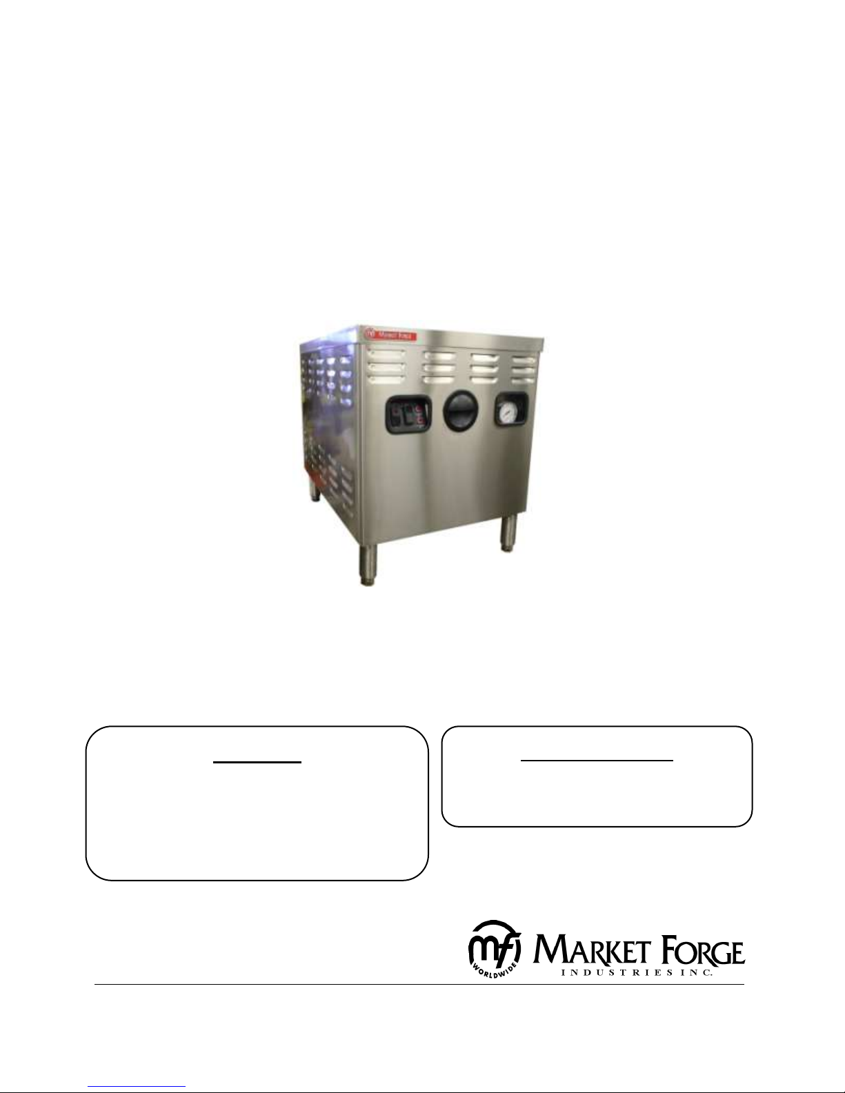
OWNER’S MANUAL
WARNING:
IMPROPER INSTALLATION, ADJUSTMENT,
ALTERATION, SERVICE OR MAINTENANCE CAN CAUSE
PROPERTY DAMAGE, INJURY OR DEATH. READ THESE
INSTALLATION, OPERATION AND MAINTENANCE
INSTRUCTIONS THOROUGHLY BEFORE INSTALLING
OR SERVICING THIS EQUIPMENT.
Form Number: S-3112 REV. E 04/14
Printed in USA 35 Garvey Street, Everett, MA 02149
Telephone (617) 387-4100, (866) 698-3188, Fax (617) 387-4456, (800) 227-2659
custserv@mfii.com, www.mfii.com
FOR YOUR SAFETY:
DO NOT STORE OR USE GASOLINE OR OTHER
FLAMMABLE VAPORS OR LIQUIDS IN THE
VICINITY OF THIS OR ANY OTHER APPLIANCE.
Electric Operated Boilers
MODELS: □ M24E24A □ M36E24A
□ M24E36A □ M36E36A
□ M24E42/48A □ M36E42/48A
Page 2

1
Table of Contents
INTRODUCTION ............................................................................................................................... 2
To the Kitchen Manager: ............................................................................................................. 2
INSTALLATION INSTRUCTIONS ........................................................................................................ 3
GAS OPERATED BOILERS ............................................................................................................. 3
RECEIVING INSTRUCTIONS: ......................................................................................................... 3
INSTALLING LEGS: ........................................................................................................................ 3
LEVELING: .................................................................................................................................... 3
SERVICE CONNECTIONS: ............................................................................................................. 4
OPERATING INSTRUCTIONS ............................................................................................................ 5
CONTROL PANEL: ........................................................................................................................ 5
OPERATING THE STEAM GENERATOR: ........................................................................................ 5
ADJUSTMENTS ................................................................................................................................ 6
SETTING THE BOILER CONTROL PRESSURE SWITCHES: .............................................................. 6
PRESSURE CONTROL SWITCH ADJUSTMENT: ............................................................................. 6
GENERAL TROUBLE SHOOTING ....................................................................................................... 7
TESTING PROCEDURE ...................................................................................................................... 9
WATER CONTROL BOARD TESTING PROCEDURE ........................................................................ 9
ILLUSTRATED PARTS LIST .............................................................................................................. 11
BOILER BASE - 24” ..................................................................................................................... 11
PRESSURE SWITCH BOX, WITHOUT COVER .............................................................................. 12
CONTROL BOX ASEMBLY, WITH & WITHOUT COVER ............................................................... 13
ELECTRIC BOILER, LEFT SIDE VIEW – 36”................................................................................... 14
ELECTRIC BOILER, FRONT VIEW – 36” ....................................................................................... 15
ELECTRIC BOILER, CONTACTOR BOX ......................................................................................... 16
ELECTRIC BOILER, ELEMENTS .................................................................................................... 17
ELECTRICAL INFORMATION .......................................................................................................... 18
Wiring Diagram for New Generation Electric Boilers ............................................................... 18
Schematic Diagram for New Generation Electric Boilers ......................................................... 19
Wiring – 18 kW, 24 kW, 32 kW ................................................................................................. 20
Wiring – 18 kW, 24 kW, 32 kW ................................................................................................. 21
Wiring – 36 kW, 42 kW, 48 kW ................................................................................................. 22
Wiring – 36 kW, 48 kW .............................................................................................................. 23
MAINTENANCE .............................................................................................................................. 24
Cleaning the Boiler: ................................................................................................................... 24
CLEANING INSTRUCTIONS: ........................................................................................................ 24
APPLICATION INSTRUCTIONS ........................................................................................................ 26
Application Instructions for Total Concept Descaler Cleaning of the Boiler ............................ 26
Page 3

2
INTRODUCTION
To the Kitchen Manager:
1. Read this manual carefully and in its entirety. Contact Market Forge Ind., Inc. for
clarification if necessary.
2. Protect your kitchen personnel from scalding and other serious injury by providing
training programs to acquaint all equipment operators with the correct and safe
methods of operation.
3. Operators must be made aware of the consequences of misuse. Steam producing
equipment, no matter who the manufacturer, is inherently dangerous when misused.
The possibility of serious scalding always exists, the careless and/or untrained operator
will be injured.
4. This equipment must be maintained according to the guidelines in this manual (see
"maintenance"). Lack of maintenance will lead to a potentially hazardous condition and
possible liability. Operators should report any equipment malfunction immediately and
steps must be taken to correct the problem before further use of the equipment is
allowed.
5. Keep this manual for daily reference.
Market Forge, in the interest of both cost and efficiency has designed these steam boilers with
the latest automatic controls in order to make it easier for the operator to use and maintain
this equipment. Standard components are utilized on all models unless variances in size or
capacity dictate a divergence from this policy for more efficiency of operation. This parts and
service manual is written and illustrated to cover all steam boiler equipment that uses gas as a
source of fuel other than those which have been custom designed under special order.
HOW TO USE THIS MANUAL:
The pictures of components are aids to the identification, disassembly and assembly of parts.
The parts listing provides information necessary for the ordering of replacement parts (proper
part names and part numbers). When requesting parts or service always furnish the model and
serial number of your complete unit, this will indicate to Market Forge Service Personnel the
type of boiler that you have. This information can be found on the nameplate attached to the
boiler frame.
THEORY OF OPERATION FOR ELECTRIC BOILER:
An explanation of how the control system operates on automatic electric boilers follows:
With the boiler filled with water to the proper level and the fuel switch is turned ON, the
contactors will pull in and permit the completion of the electric circuit to the heating element.
When the boiler builds to its set pressure, the pressure switch opens. This will open the circuit
to the coil in the contactor, which in turn will drop put the contacts in the contactor and shut
off the electricity. As the pressure in the boiler drops the pressure control switch will again
complete the circuit and build the boiler back to its set pressure. To stop all steam generation
place the fuel switch to the OFF position.
Page 4

3
INSTALLATION INSTRUCTIONS
WARNING:
READ THIS BEFORE OPENING THE
SHIPPING CONTAINER!
ELECTRIC OPERATED BOILERS
MODELS: • M24E24A • M36E24A
• M24E36A • M36E36A
• M24E42/48A • M36E42/48A
CAUTION: BE SURE TO READ:
DO NOT AT ANY TIME LAY THE EQUIPMENT DOWN ON ITS BACK, SIDE, TOP OR FRONT. Doing
so may damage the equipment and invalidate the warranty.
RECEIVING INSTRUCTIONS:
Inspect the equipment before signing the bill of lading. The equipment supplied was tested and
inspected before shipment. The carrier accepted it as complete and without damage.
This merchandise became your property when it was accepted by the carrier at the factory.
Market Forge cannot assume responsibility for loss or damage during transit.
For this reason, you should immediately inspect for visible and concealed damage or shortages
before signing for shipment as follows:
1. Count the number of cartons and packages received to be sure they coincide with the
bill of lading.
2. Visually check all cartons for external damage.
3. Remove all cartons from their skids to examine equipment for concealed damage. The
carton is nailed and strapped to the skid. It will be necessary to cut the straps and pry
off the container.
4. After inspection, replace the cartons over the equipment on the skids to protect and
secure the equipment until it is ready for installation.
5. Sign for shipment if all is in order. Note shortages, external and concealed damage, if
any, on the bill of lading before accepting a partial or damaged shipment.
6. If necessary, contact the carrier immediately to file a claim. All claims must be filed by
the receiver.
7. Do not remove the cartons or the skids from the cooking equipment until the unit has
been transported through the building to the actual set-up location. The cartons should
remain on the equipment as protection against dents and scratches.
INSTALLING LEGS:
Some models are shipped without legs. A separate carton will contain the legs. If your model is received
this way, be sure to follow the installation instruction sheet packed with the legs.
LEVELING:
In order for the boiler to drain correctly, it is important to use a level on cabinet top both left
and right and front-to-back. If not level, adjust feet. On compartment cookers, check the
interior shelves for level condition.
Page 5
4
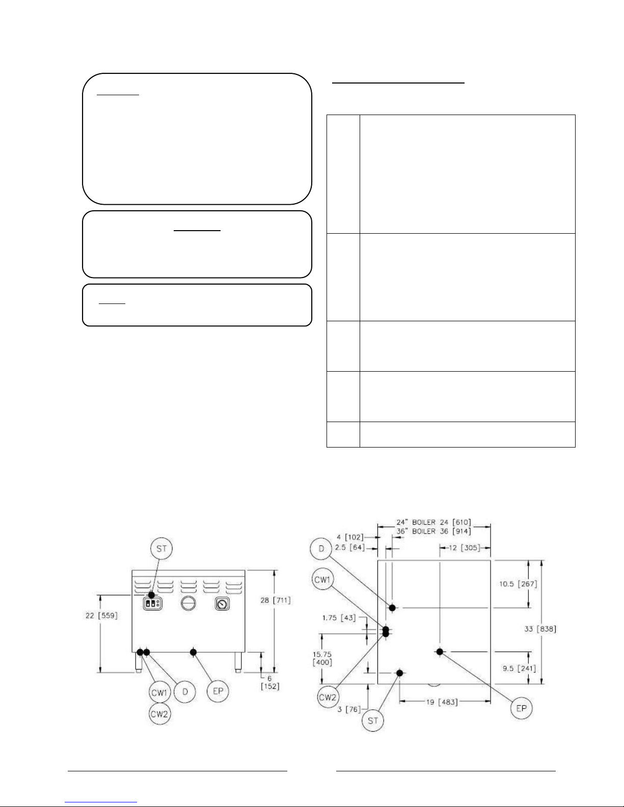
SERVICE CONNECTIONS:
Electric Operated
EP
Power Supply – Use wire suitable for at least
90oC nominal amp per line wire:
24kW
36kW
42kW
48kW
Volts
3 pH
3 pH
3 pH
3 pH
208 (197-219)
66
100
117
--
240 (220-240)
60
91
--
116
480 (360-500)
32
47
--
58
Details of other electrical systems available upon
request
CW1
Cold Water - 3/8” (10mm) O.D. tubing for cold
water to boiler. Cold water lines will have a max
of 50PSI (3.5 kg/cm2) and a min of 25PSI (1.8
kgcm2) water pressure. CAUTION: FILTER
SYSTEM INSTALLATION INSTRUCTIONS MUST BE
ADHERED TO WHEN CONNECTING A FILTER TO
THIS LINE.
CW2
Cold Water - 3/8” (10mm) O.D. tubing for cold
water to condenser. Cold water lines will have a
max of 50PSI (3.5 kg/cm2) and a min of 25PSI (1.8
kg/cm2) water pressure.
D
Drain - Pipe full 2” (51mm) IPS to flush floor
drain capable of receiving water flowing at a max
rate of 5 gallons (19 liters) per minute. DO NOT
MAKE SOLID CONNECTION TO FLOOR DRAIN.
ST
Steam Take-off - Connection for operation of
adjacent steam powered equipment.
NOTE: If equipment is installed where elevation exceeds
2,000 feet (609.6 meters) above sea level, specify
installation altitude so that proper gas orifices can be
provided.
CAUTION: Before connecting water to this unit,
water supply should be analyzed to make sure
hardness is no greater than 2.0 grains and pH
level is within the range of 7.0-8.5. Water which
fails to meet these standards should be treated
by installation of water conditioner.
EQUIPMENT FAILURE CAUSED BY INADEQUATE
WATER QUALITY IS NOT COVERED UNDER
WARRANTY.
NOTE: PVC & CPVC PIPE ARE NOT ACCEPTABLE
MATERIALS FOR DRAINS.
WARNING:
DO NOT UNDER ANY CIRCUMSTANCE CONNECT
THE EXHAUST DRAIN LINE DIRECTLY TO A SEWER
LINE.
WASTE LINE INSTALLATION: The drain port of the unit
is marked with a colored tag and is located at the
lower rear left side of the boiler as viewed from the
front. This exhaust line may be left open if the boiler
has to be situated in a tiled floor depression or a tiled
curb section that is equipped with drain facilities. If
this is not the case, then a 2” (51mm) NPT. drain line
must be connected to divert the exhaust to the floor
drain. If it is necessary to use more than three elbows,
increase the size of the waste line accordingly.
NOTE: The only available space to supply utilities to
the gas boiler is the 6” (152mm) space between the
floor and the cabinet. Allow 3” (76mm) space from
side wall and 6” (152mm) from real wall if adjoining
walls are combustible.
INSTALLATION INSTRUCTIONS
Page 6
5
OPERATING INSTRUCTIONS
OPERATING INSTRUCTIONS FOR STEAM GENERATORS
FIRST CHECK TO BE SURE THAT:
A. WATER SWITCH IS IN THE OFF POSITION.
B. WATER SUPPLY VALVE IS OPEN.
C. ELECTRICITY IS CONNECTED TO ALL UNITS.
D. THEN PROCEED WITH DAILY OPERATING PROCEDURES.
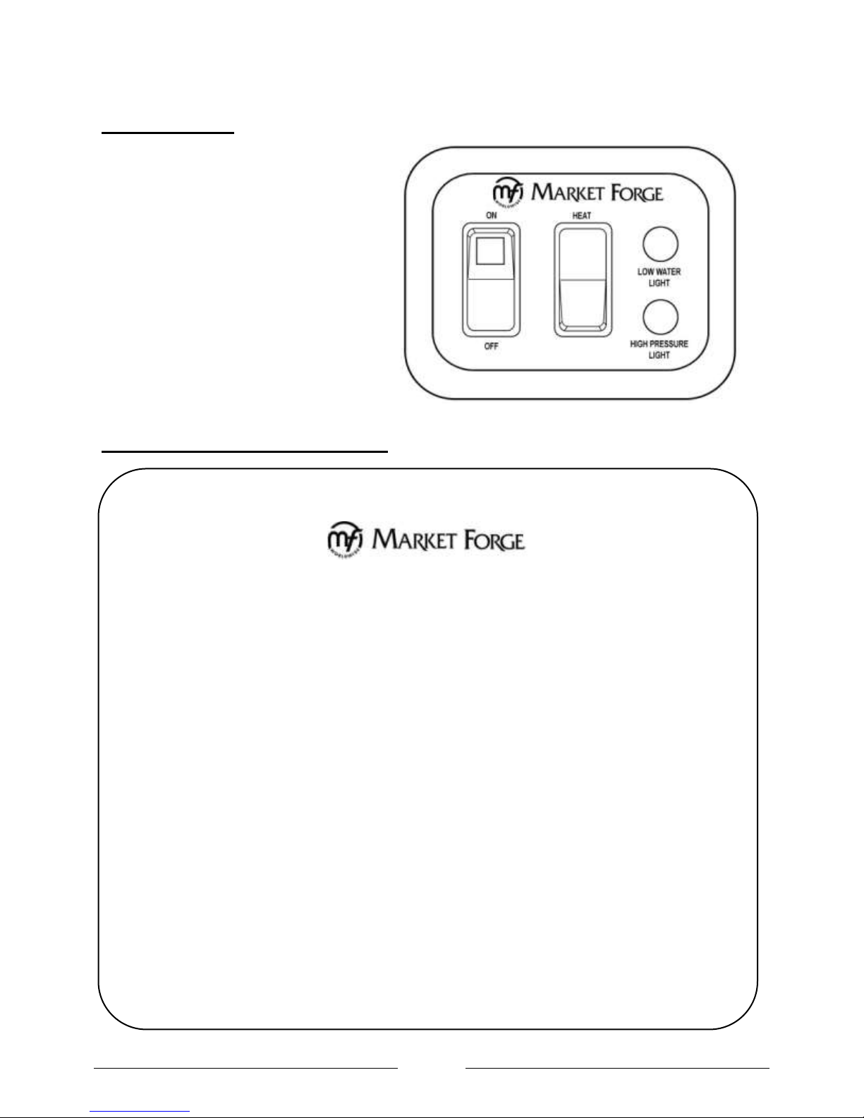
DAILY OPERATING PROCEDURE:
STEP 1: PRESS WATER SWITCH FROM OFF TO ON.
STEP 2: WAIT 5-10 MINUTES FOR WATER TO FILL IN STEAM GENERATOR (GAUGE GLASS
SHOULD BE 2/3 FULL.)
STEP 3: PRESS HEAT SWITCH FROM ON TO OFF AND RELEASE BACK TO ON WHEN THE
LOW WATER LIGHT GOES OFF. GREEN INDICATOR LIGHT WILL COME ON. (THIS
IS NECESSARY TO MANUALLY RESET THE UNIT.)
DAILY SHUT DOWN AND CLEANING:
STEP 1: STEP 1 PRESS WATER SWITCH OFF. THIS WILL DRAIN THE STEAM GENERATOR.
STEP 2: STEP 2 AFTER STEAM GENERATOR HAS COMPLETELY DRAINED REPEAT
STEP 3: STEPS 1 & 2 OF DAILY OPERATING PROCEDURE.(WATER TO REMAIN IN STEAM
GENERATOR UNTIL NEXT DAILY USE.)
CONTROL PANEL:
MODELS: • M24E24A
• M24E36A
• M24E42/48A
• M36E24A
• M36E36A
• M36E42/48A
OPERATING THE STEAM GENERATOR:
OPERATING INSTRUCTIONS
OPERATING INSTRUCTIONS
Page 7
6
ADJUSTMENTS
WARNING:
Because power must be on to adjust pressure switches, be sure to protect against electrical shock.
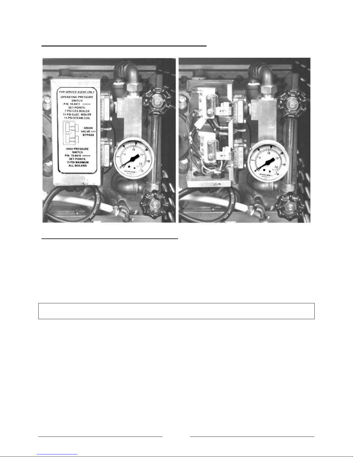
SETTING THE BOILER CONTROL PRESSURE SWITCHES:
PRESSURE CONTROL SWITCH ADJUSTMENT:
If boiler fails to maintain steam pressure in operating range, pressure control switch may require
adjustment.
1. Start boiler and allow pressure to build up to operating level - 15 PSI (1kg/cm²).
2. Check boiler pressure gauge. If gauge indicates 12 to 14 PSI, pressure control switches are
properly adjusted.
3. If boiler does not come on when pressure gauge reads 7 PSI and does not go off when pressure
gauge reads 14 PSI, proceed as follows:
a) Remove screw and lift front cover off control box.
b) Hand adjust operating pressure control switch and high limit pressure control switch by turning
adjusting nut (Knurled knob) clockwise to raise and counter clockwise to lower actuation point.
Switch should be set so that boiler comes on when boiler pressure gauge reads 12 PSI and goes
off when gauge reads 14 PSI. Switch should be set so that boiler will shut off if pressure reaches
15 PSI.
c) The actuation value (differential) is factory set and cannot be changed.
d) The cold water condenser thermostat is preset at factory.
e) Repeat steps, 1, 2, and 3. If 12 to 14 PSI boiler pressure gauge reading is obtained during boiler
operation, adjustment is correct. If proper adjustment cannot be made consult TroubleShooting Guide in this manual.
f) After making adjustments, replace cover on pressure switch box and screw.
Page 8

7
GENERAL TROUBLE SHOOTING
TROUBLE
POSSIBLE CAUSE
REMEDY
Water does not enter the
boiler.
a. Water main shut-off.
b. Power not reaching unit.
c. Probes dirty.
d. Water level control board
defective.
e. Solenoid valve defective.
a. Turn on.
b. Check main fuse or circuit.
c. Remove and clean.
d. See (page 9) for test procedure.
e. If 120V is verified at solenoid
coil, but fails to open, replace
solenoid.
Boiler fails to build up
pressure when water level
is proper and fuel switch is
turned on.
a. Check to see that circuit
breaker in main is turned on.
b. Check to see that contactors
are pulling in.
c. Current flow is broken at
water level control (ascertain
with continuity check).
d. Current flow is broken at
pressure control or high limit
control switches due to
maladjustment or defect
(ascertain with continuity
check).
e. Heating elements are
defective.
a. Check for voltage at terminal
block.
b. Check continuity of coil, if open
replace.
c. Check for voltage at L1 and L2,
replace if defective.
d. Readjust - to proper setting -
refer
b. to instructions for
readjustment, replace if
defective.
c. 5. Replace if continuity check
through the circuit of each
element shows defective.
Boiler fails to reach full
operating pressure of 5
lbs. or 15 lbs.
a. Pressure gauge reads
inaccurately.
b. Pressure control and high limit
control switches are out of
adjustment.
c. Safety valve not seating
properly.
d. Contactor coils (one or both)
not energizing and closing
circuit to the heating
elements.
a. Replace.
b. Follow instructions for
readjusting or replace if
defective.
c. Clean or replace.
d. Check - replace either
contactor coils or complete
contactor – if found defective.
Measure amperage at terminal
block check to be sure there is
an even draw on all three
phases - see wiring diagrams
for correct AMP draw. If
uneven or zero amperage draw
is found on one of the three
phases, check for blown fuse. If
fuse is OK, shut off power,
remove wires from heating
elements and run continuity
check - replace if defective.
GENERAL TROUBLE SHOOTING
Page 9
8
TROUBLE
POSSIBLE CAUSE
REMEDY
Water enters boiler very
slowly.
a. Dirty Strainer screen in
solenoid valve.
a. Clean or replace strainer screen,
part no. 08-4871.
Water level in gauge glass
fluctuates up and down.
a. Top shut off on water gauge is
closed.
a. Open.
Contactor chatters.
a. Incorrect supply voltage.
b. Dirty or worn contactor points.
c. Weak coil.
a. Check to see that it matches it
with coil contactors.
b. Clean or replace contactor.
c. Replace with correct voltage
coil.
15 lbs. safety valve blows
off prematurely.
a. Pressure set too high.
b. Pressure gauge reads
incorrectly.
c. Mineral build-up or dirt on
seat of valve.
d. Weak spring valve.
a. Readjust.
b. Replace.
c. Clean.
d. Replace valve.
Boiler build up to
pressure, shuts down and
fails to come on.
a. High limit switch set too low
or operating pressure control
switch set too high.
a. Follow instructions for
readjusting, (see page 6), or
replace if defective.
Air vent leaking.
a. Not closing.
a. Replace.
Cold water condenser
does not function.
a. Main water line shut off.
b. Thermostat defective.
c. Tighten coil nut.
d. Check solenoid coil for
continuity, if open replace.
a. Turn on.
b. Replace if defective.
c. Tighten coil nut.
d. Check coil for continuity, if
open replace.
Product in cooker does
not cook properly on first
cycle, but cooks alright
after first cycle is
exhausted.
a. Air vent is closing.
a. Replace.
Contactor chatters.
a. Low voltage.
b. Defective or incorrect coil.
a. Check voltage condition. Check
momentary voltage dip during
starting. Low voltage prevents
magnet sealing. Check coil
voltage rating.
b. Replace coil, rating of coil must
match the line voltage.
Welding or freezing.
a. Abnormal spike in current.
b. Low voltage preventing
magnet from sealing.
c. Short circuit.
a. Check for grounds or shorts in
system.
b. Correct voltage condition.
c. Remove short fault and check
to be sure fuse or breaker size
is correct
Page 10

9
GENERAL TROUBLE SHOOTING
TROUBLE
POSSIBLE CAUSE
REMEDY
Short contact button life
and / or overheating of
contacts.
a. Filling or dressing.
b. Interrupting excessively high
current.
c. Discolored contacts caused by
insufficient contact pressure,
loose connection, etc.
d. Dirt or foreign matter on
contact surface.
e. Short circuit.
a. Do not file silver tips. Rough
spots or discoloration will not
harm tips or impair their
efficiency.
b. Check for grounds, shorts or
excessive current.
c. Check contact carrier for
deformation or damage, clean
and tighten connections.
d. Clean with Acetone.
e. Remove fault and check to be
sure fuse or breaker size is
correct
TROUBLE
POSSIBLE CAUSE
REMEDY
Open circuit.
a. Mechanical damage.
b. Burnt-out coil due to
overvoltage or defect.
a. Handle and store carefully. Do
not handle coils by the leads.
b. Replace coil.
Overheated Coil.
a. Over-voltage or high ambient
temperature.
b. Wrong coil.
c. Shorted turns caused.
d. Under voltage, failure of
magnet to seal in.
a. Check application and circuit.
b. Check rating (voltage and
frequency) if incorrect, replace
with proper coil.
c. Replace coil.
d. Correct system voltage. Install
new coil.
COILS
WATER CONTROL BOARD TESTING PROCEDURE
TESTING PROCEDURE
Page 11

10
Tools Needed:
Digital or Analog V-O-M meter.
Alligator clip type test jumpers (2
sets min.).
Turn Off Power to Control:
Use V-O-M to verify there is no
power at terminals L 1 & L2.
Use V-O-M to verify that there is
no power at terminals ‘FW(NO)’,
‘LO LlTE(NC)’ & ‘HTR(NO)’. If there
is power at any of these terminals,
you will need to find the source
and turn it off.
Remove Wires from Probe and Relay
Switch Terminals:
DO NOT remove wires from L 1 &
L2 terminals.
Tag wires and remove from probe
and relay contact terminals
including ‘GND’ terminal.
Tag and remove wires from
‘RESET’ terminals.
Connect jumper wire to both
’RESET’ terminals.
Turn Power On to Terminals L 1 & L2:
‘LED l’ should turn on.
‘LED 2’ should be off.
‘LED 3’ should be off.
Use V-O-M to verify that there is
power at ‘FW(NO)’ & ‘LO LlTE(NC)’
terminals and no power ‘HTR(NO)’
terminals
Test Feedwater Function:
Connect jumper wire to ‘FW HIGH
and ‘GND’ terminals.
‘LED l’ should turn off after a 10
second delay.
Use V-O-M to verify that there is no
power at the ‘FW (NO)’ terminal.
Remove jumper from ‘FW HIGH’
and ‘GND’ terminals. . ‘LED l’ should
turn on.
Use V-O-M to verify that there is
power at the ‘FW(NO)’ terminal.
Test Primary Low Water Function:
Connect jumper wire to ‘LW(1)
and‘GND’ terminals.
‘LED 2’ should turn on.
Remove jumper wire from ‘LW(1)’
and ‘GND’ terminals.
‘LED 2’ should turn off after a 3
second delay.
Connect jumper wire to ‘LW(1)’ and
‘GND’ terminals.
‘LED 2’ should turn on.
Use V-O-M to verify that there is
power at the ‘LO LlTE(NC)’terminal
and no power at the ‘HTR(NO)’
terminal.
Remove the jumper wires from the
‘RESET’ terminals.
‘LED 3’ should turn on.
Use V-O-M to verify that there is
no power at the ‘LO LlTE(NC)’
terminal and power at the
‘HTR(NO)’ terminal.
Connect jumper wire to ‘RESET’
terminals.
Remove jumper wire from ‘LW(2)’
and ‘GND’ terminals.
‘LED 3’ should turn off after a 3
second delay.
USE V-O-M to verify that there is
power at the ‘LO LlTE(NC)’ terminal
and no power at the ‘HTR(NO)’
terminal.
Connect jumper wire from ‘LW(2)’
and ‘GND’ terminals.
‘LED 3’ should remain off.
IMPORTANT:
Jumper wire between ‘LW(1) and
‘GND’ terminals must remain in place
to test secondary low water function.
IF ANY OF THE FUNCTIONS DO NOT
WORK, REPLACE THE BOARD!
Test Secondary Low Water Function:
Connect jumper wire to ‘LW(2)’ and
‘GND’ terminals.
‘LED 3’ should remain off.
IF ALL FUNCTIONS WORK, TROUBLE-
SHOOTING OTHER COMPONENTS WILL
BE REQUIRED!
This test procedure is to be used
to determine if the control is
working properly. It is not
intended to determine why the
control may have failed.
If testing shows that the control is
operating properly, check all
probe and solenoid wiring and the
condition of the electrodes in the
steam chamber.
Contact the factory if the boiler
still does not operate properly
after completing the testing.
LED 1
LED 2
LED 3
RESET
LW2
GND
LW1
FW - HIGH
HTA NO
LO LITE (NC)
FW (NO)
L1
L2
Page 12

11
ILLUSTRATED PARTS LIST
ITEM NO.
PART NO.
DESCRIPTION
1
08-5894
Market Forge Nameplate Log
2
91-5795
Handle, Front
3
98-3992
Panel, Front Assy, 24”
98-3993
Panel, Front Assy, 36”
4
10-0631
Leg, 6”
08-5211
Leg, 10”
08-5208
Leg, Flanged 6”
08-5206
Leg, 8”
10-0326
Caster, 5”
5
98-3968
Trim, Edge
6
98-3978
Glass
7
98-3991
Gasket, Adhesive
8
98-3994
Panel, Side Assy
9
98-3995
Panel, Rear Assy, 24”
98-3996
Panel, Rear Assy, 36”
1
3
4 8 2
9
7 5 6
5
BOILER BASE - 24”
Page 13

12
ITEM NO.
PART NO.
DESCRIPTION
1
94-5064
Box, Pressure Switch
2
10-8410
Pressure Switch, Hi-Limit
3
10-8411
Pressure Switch, Operating
4
98-3875
Switch, Drain By-Pass
5
08-7933
Manifold, Pressure Switches
6
10-4804
Pressure Gauge
3
2
1
4 5 6
ILLUSTRATED PARTS LIST
PRESSURE SWITCH BOX, WITHOUT COVER
Page 14

13
ILLUSTRATED PARTS LIST
ITEM NO.
PART NO.
DESCRIPTION
1
08-6549
Switch, Power
2
94-5127
Switch, Manual Reset
3
10-5052
Light, Red
4
94-5003
Control Box Lexan
5
08-6469
Fuse Holder
6
98-1680
Board, Water Level Control
7
08-6472
Relay Tube
8
08-6475
Relay Base
9
98-3877
Relay Bracket
10
08-6468
Fuse, 5A
CONTROL BOX ASEMBLY, WITH & WITHOUT COVER
Page 15

14
ILLUSTRATED PARTS LIST
ITEM NO.
PART NO.
DESCRIPTION
1
10-0239
Hose, Drain
2
10-4137
Clamp, Hose
3
91-6927
Box, Drain Assy.
4
10-5234
Transformer
5
10-1058
Valve, Cold Water Condenser, 120V
6
08-4822
Valve, Boiler Feed
7
08-7959
Hose, Condense
8
98-3894
Copper Nozzle
9
98-1401
Valve, Check
10
10-0287
Hose, Drain
11
10-4137
Clamp, Hose
12
08-7974
Clamp Hose
13
98-3914
Compression Fitting
14
10-4556
Air Vent
15
08-4900
Manual Valve, Water Inlet
16
98-3892
Thermostat, Cold Water Condenser
16
ELECTRIC BOILER, LEFT SIDE VIEW – 36”
Page 16

15
ILLUSTRATED PARTS LIST
ITEM NO.
PART NO.
DESCRIPTION
1
10-1311
Valve, Drain, 120V
2
10-5320
Valve, Safety, 15PSI
3
98-1667
Cover, Front, Contactor Box
4
94-5065
Cover, Pressure Switch Box
5
08-5447
3/4” NPT, Brass Street Elbow
6
10-2728
Water Gauge Glass Assembly
6a
10-4754
Water Gauge (Glass Only)
7
08-7933
Pressure Switch Manifold
8
08-5427
3/4” Br. Nipple, 2 1/2” Lg.
9
08-4991
3/4” Side Outlet Tee
10
10-7943
3/4” Brass Union
11
10-1126
3/4” Nipple, 2” Brass
12
10-3455
90O Elbow
Not Shown
98-1656
Cover, Rear, Contactor Box
ELECTRIC BOILER, FRONT VIEW – 36”
Page 17

16
ILLUSTRATED PARTS LIST
ITEM NO.
PART NO.
DESCRIPTION
1
98-1670
Box, Contactor
2
10-5944
Contactor
3
98-1720
Terminal Block
4
08-6553
Hi-Limit Thermostat
5
10-5220
Ground Lug
6
08-7981
Terminal Strip
7
98-1663
Bracket, Contactor Mounting
8
98-4014
Bracket, Contactor Tray
ELECTRIC BOILER, CONTACTOR BOX
Page 18

17
ILLUSTRATED PARTS LIST
ITEM NO.
PART NO.
DESCRIPTION
1
98-1659
Plate, Front
2
98-1673
Gasket, Front Plate
3
91-8660
Gasket, Htg. Element
4A
08-6485
Heating Element, 9kW, 208 Volts
4B
08-6486
Heating Element, 9kW, 240 Volts
4C
08-6487
Heating Element, 9kW, 480 Volts (a.k.a 277 Volts)
4D
08-6415
Heating Element, 12kW, 208 Volts
4E
08-6416
Heating Element, 12kW, 240 Volts
4F
08-6417
Heating Element, 12kW, 480 Volts (a.k.a 277 Volts)
4G
08-6491
Heating Element, 14kW, 208 Volts
4H
08-6418
Heating Element, 16kW, 208 Volts
4J
08-6419
Heating Element, 16kW, 240 Volts
4K
08-6420
Heating Element, 16kW, 480 Volts (a.k.a 277 Volts)
5
08-6337
Water Level Probe
6A
98-3936
Screw, 1/4-20 Socket Set Screw, Stainless Steel
6B
08-7840
Nut, 1/4-20 Flanged
Gasket Heating Element
6A
6B
ELECTRIC BOILER, ELEMENTS
Page 19

18
ELECTRICAL INFORMATION
Wiring Diagram for New Generation Electric Boilers
Page 20

19
ELECTRICAL INFORMATION
Schematic Diagram for New Generation Electric Boilers
Page 21

20
ELECTRICAL INFORMATION
Wiring – 18 kW, 24 kW
Page 22

21
ELECTRICAL INFORMATION
Wiring – 18 kW, 24 kW
Page 23

22
ELECTRICAL INFORMATION
Wiring – 36 kW, 42 kW, 48 kW
Page 24

23
ELECTRICAL INFORMATION
Wiring – 36 kW, 48 kW
Page 25

24
MAINTENANCE
NUMBER REQUIRED
PART NO.
1 Access Cover Gasket (8”) Boiler
91-8756
1 Access Cover Gasket (12”) Boiler
98-1673
1 Set of Rubber & Brass Washers
90-0039
1 Market Forge Cathodic Descaler (all boilers) new style
08-0049
1 Sealing Washer
10-2455
Cleaning the Boiler:
Market Forge recommends that the boiler be cleaned periodically due to impurities introduced through
the water supply. All water supplies contain some mineral deposits and impurities; the degree varies
with geographic location. Market Forge is recommending a cleaning schedule that will keep your
equipment in proper, safe working order where water supplies are relatively pure. Because no water
supply can be accurately compared with that of another, this section should not be regarded as fool
proof. A stepped-up, more frequent cleaning schedule may be required when excessive impurities exist.
The Cleaning schedule should be performed two or more times per year as governed by the local water
conditions. Market Forge recommends the use of its “cathodic descaler” to protect the inner boiler walls
and components against rust, scale and lime deposits. The normal effectiveness of a descaler is one
year. The schedule for changing the “cathodic descaler” may be timed to the cleaning schedule or
accelerated as noted above.
Market Forge qualified service agencies are available to establish a suitable schedule for TOTAL
CONCEPT cleaning and descaler replacement.
REPLACEMENT PARTS NEEDED TO COMPLETE THESE INSTRUCTIONS
CLEANING INSTRUCTIONS:
1. Move the HEAT and POWER switch to their OFF positions. On electric models also turn off the
electric power at the main switch. This will allow the boiler to empty.
WARNING: (ALL BOILERS ) DISCONNECT THE 115 VOLT POWER SUPPLY.
2. Remove the hand-hole cover as follows: (Refer to Fig. 1)
a. Remove pressure switch box at the plumbing union and move it out of the way.
b. With an open end wrench back off the hex-nut, counterclockwise, so only two threads are
holding it. Then remove the pressure switch box and set aside.
c. With a blunt instrument, strike the hand-hole cover until its seal is broken.
d. Remove the hex-nut from the remaining two threads, slide off the washer and channel yoke
do not allow the hand-hole cover to drop inside.
e. Remove the hand-hole cover by turning it so that it will pass through the opening. Remove
the bolt and dynaseal. Discard the hand-hole gasket and dynaseal washer.
Page 26

25
MAINTENANCE
Cathodic
Descaler Rod
3. Clean rust, scale and lime deposits from the inside of the boiler with a wire brush.
DO NOT DAMAGE COPPER HEATING ELEMENTS - BRUSH LIGHTLY. WORK DEPOSITS TO REAR
CORNER AND REMOVE WITH PUTTY KNIFE.
4. After removing all debris, flush out with clean water through the hand-hole and drain .
5. Clean the hand-hole cover with a wire brush and wash. Be sure the areas that contact the gasket
and dynaseal are clean and smooth.
6. To protect against further scale and corrosion remove the old cathodic descaler. Install a New
Market Forge Cathodic Descaler Rod.
7. Clean the water gauge glass as follows:
a. Move the heat and power switch to their off positions. This will allow the boiler to empty.
b. Unscrew the fittings from both valves and slide them toward the center of the gauge glass.
Push the water gauge glass downward compressing the rubber washer in the lower valve
allowing the glass to be removed.
c. Remove and discard the two rubber and brass washers. Slip off the two valve fittings and
clean the water gauge glass.
d. Reassemble by reversing the above steps with new rubber and brass washers (see image
below).
Page 27

26
Application Instructions for Total Concept Descaler Cleaning of the Boiler
GENERAL NOTES:
Total Concept is designed to be used with water
between 160°F to 200°F.
Preheating is required on the boiler to raise the
water temperature to the acceptable range.
(160°F to 200°F).
Total Concept is a NSF listed nonfood product.
This is a liquid acid (nonmuriatic) product that
works without fumes, odors, and hazards
associated with other harsh chemicals. Product
is also USDA Approved.
BOILER TREATMENT CLEANING INSTRUCTIONS:
After determining proper location for
cleaner/descaler to be added: Read complete
instructions thoroughly; including all warning
and cautionary statements.
Figure 1
1. Energize boiler and fill to operating level.
Figure 2
2. Energize heating circuit to pre-heat unit.
Figure 3
Figure 4
3. AUTOMATIC - After unit is pre-heated, cycle
the power switch to the OFF position then
immediately back to the ON position.
Figure 5
4. Remove the shipping cap, replace it with the
pouring cap. Cut the tip of the pouring cap at
the first notch to a 45
o
angle.
5. Install the tubing firmly over the tip of the
pouring cap.
Size: Case of 4 -1 Gallon Bottles / Part No. 20-0307 or 1-1 Gallon Bottle / Part No. 20-0307X
APPLICATION INSTRUCTIONS
Page 28

27
Application Instructions for Total Concept Descaler Cleaning of the Boiler
Figure 6
6. Energize compartment to release steam
pressure in boiler to “0” PSI before removing
pipe plug.
7. Remove the plug from the access port on the
steam header pipe inside cabinet doors.
CAUTION: HEADER PIPE & ACCESS PLUG
ARE HOT.
Figure 7
8. Feed the tubing through the access port in the
boiler compartment (figure 8).
Figure 8
NOTE: A minimum of 12” must be inserted.
Figure 9
9. Tilt the container, pour the contents into the
unit.
10. When empty, refill the container with hot tap
water and add to boiler for cleaning. Repeat
twice. This additional 2 gallons of water will
cause the low water probe to be immersed in
cleaner/descaler solution.
Replace access plug.
11. After rinsing the container, place tubing
inside the bottle, cover with shipping cap,
dispose of properly. DO NOT REUSE
CONTAINER.
12. DO NOT ENERGIZE HEATERS. Allow 2
hours for cleaning.
13. After time has elapsed, drain the boiler.
14. Refill the boiler and drain. Repeat this step
twice.
15. Bring the boiler to temperature and cycle
steam to the cooker compartment to purge
cleaner/descaler from the steam supply
lines. Repeat this step twice.
16. Boiler is now ready for use.
Size: Case of 4 -1 Gallon Bottles / Part No. 20-0307 or 1-1 Gallon Bottle / Part No. 20-0307X
APPLICATION INSTRUCTIONS
 Loading...