

Page 1

FT-20CE
ELECTRIC TABLE TOP TILTING KETTLE
PARTS AND SERVICE MANUAL
EFFECTIVE SEPTEMBER 12, 2014
The Company reserves the right to make substitution in the event that items specied are not available.
ERRORS: Descriptive and/or typographic errors are subject to correction.
44 Lakeside Avenue, Burlington, Vermont 05401 USA Telephone: (802) 658-6600 Fax: (802) 860-3732
Superseding All Previous Parts Lists.
MARKET FORGE INDUSTRIES
www.mi.com
P/N 14-0353 Rev A (9/14)
Page 2

TROUBLESHOOTING
SAFETY VALVE MAINTENANCE AND TESTING
CAUTION
Under normal operating conditions a “try lever
test” should be performed every two months.
Under severe service conditions, or if corrosion and/or deposits are noticed within the
valve body, testing must be performed more
often. A “try lever test” should also be performed at the end of any non-service period.
CAUTION
Hot, high pressure uid may be discharged
from body drain and vent during “try lever”
test. Care must be taken to avoid any bodily
contact.
CAUTION
High sound levels may be experienced during
“try lever” test. Wear proper safety equipment and exercise extreme care! Test at, or
near, half of the operating pressure by holding
the test lever fully open for at least two sec-
onds to ush the valve seat free of sediment
and debris. Then release lever and permit the
valve to snap shut.
If lift lever does not activate, or there is no
evidence of discharge, turn off equipment immediately and contact a licensed contractor or
qualied service personnel.
VENTING INSTRUCTIONS
Check vacuum/pressure gauge when kettle is cold.
Gauge should be in the green vacuum zone (25 - 30 In.
Hg or 84 - 100 kPa). If not, air is present which must be
vented (removed) for proper heating. Use the following
procedures to vent air:
1. With the kettle empty, place power switch in ON position.
2. Set temperature control thermostat to ‘10'. Heat kettle until heat indicator light goes off.
3. Using a 7/16" wrench, open bleed vent (rear of kettle)
one full turn for 10 seconds and close.
4. Cool kettle. Check for proper vacuum in the green
vacuum zone (25 - 30 In. Hg or 84 - 100 kPa). If reading is not low enough, repeat steps 1 to 3.
ADDING WATER (LOW WATER LIGHT COMES ON)
It may be necessary to replenish water in the jacket when
the low water indicator comes on. Do so as follows:
1. Unit should be completely cold and off.
2. Lift handle of pressure relief valve to release vacuum
in kettle. (Relief valve is at left rear of kettle).
3. Remove air vent nut at the rear of the unit.
4. Using pure distilled water only, pour 140 . oz. (4 L)
into the opening. (A funnel will be helpful). Water will
enter the kettle slowly, as air must escape through the
same hole.
5. When sufcient water has been added, replace and
tighten the nut. Be sure to seal threads with a pipe
joint compound suitable for steam at 50 psi.
6. Vacuum must be re-established. (See Venting Instructions).
SEPTEMBER 12, 2014 2 FT-20CE ELECTRIC TILTING KETTLE
Page 3
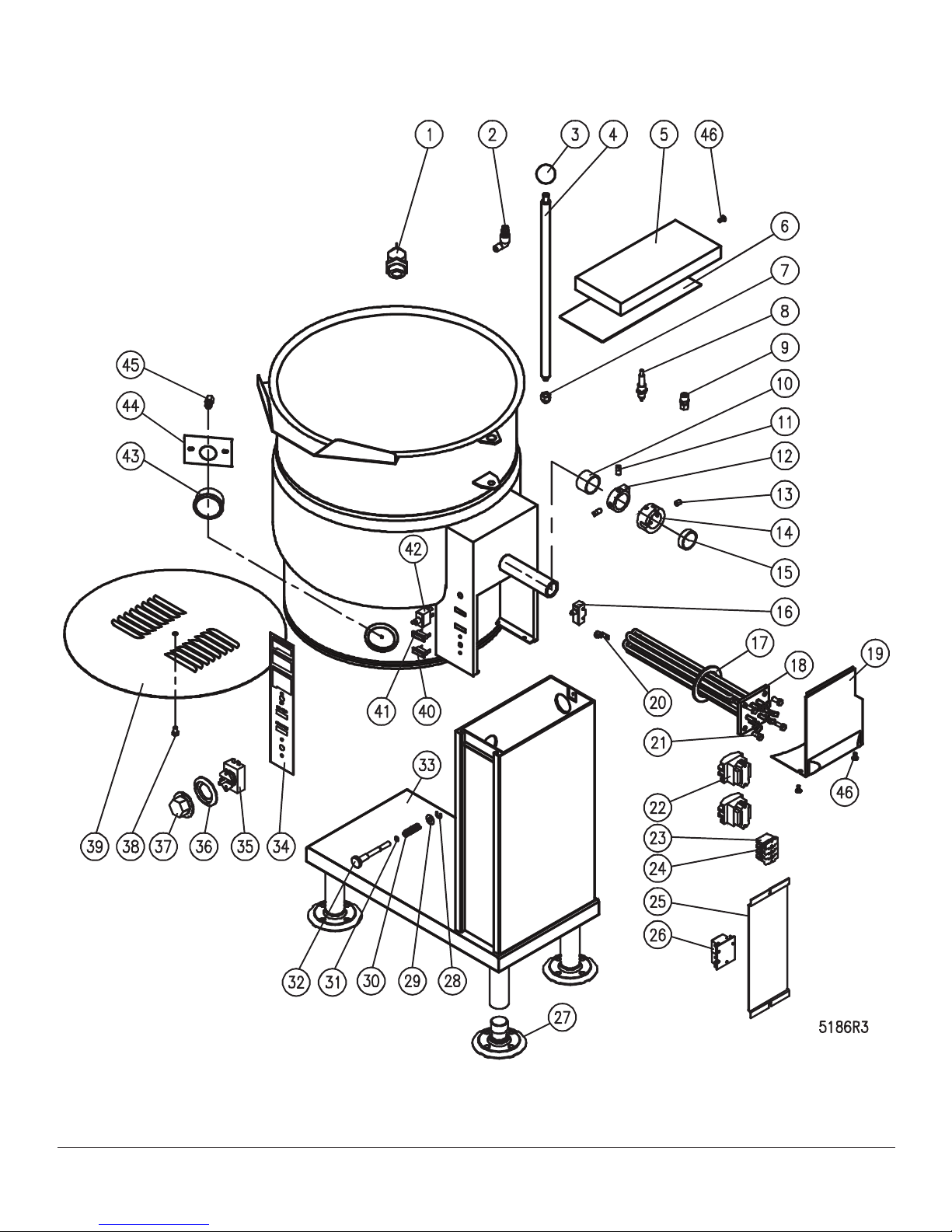
ILLUSTRATED PARTS LIST
SEPTEMBER 12, 2014 3 FT-20CE ELECTRIC TILTING KETTLE
Page 4

ILLUSTRATED PARTS LIST
ITEM PART NO. DESCRIPTION QTY
1 97-5009 Relief Valve, 50 PSI 1
* 97-6368 Down Tube 1
2 97-5415 Air Vent Assembly 1
3 97-5008 Phenolic Knob 1
4 97-7145 Handle 1
5 97-6993 Console Cover 1
6 97-6965 Console Cover Gasket 1
7 97-7342 Acorn Nut, 1/2 - 13 NC 1
8 97-5425 Probe 1
9 97-5619 Thermostat Probe Fitting 1
10 97-5341 Inner Bearing 1
11 97-7112 Set Screw, 3/8 - 16 x 1/2” 2
12 97-6518 Actuating Collar 1
13 97-7139 Hex Socket Set Screw, 3/8 - 16 x 1/2” 1
* 97-7141 Spring Pin 1/4 x 2-1/4" LG 1
14 97-7140 Cam Collar 1
15 97-5340 Outer Bearing 1
16 97-5414 Interlock Switch 1
17 97-5025 Element Gasket 1
18 **
19 97-9007 Trunnion Box Cover 1
20 97-5052 Ground Lug 1
21 M50S51618-34 Hex Bolt 5/16-18 x 3/4" 4
22 **
23 10-6962 Terminal Block End Section 1
24 10-6963 Terminal Block Section 3
25 97-5657 Component Mounting Plate 1
26 97-7125 Liquid Level Control 1
27 97-5032 Flanged Adjustable Feet 4
28 97-6677 External Ring 1
29 97-6678 Washer 2
30 97-5917 Spring 1
31 97-6679 “O” Ring 1
32 97-6680 Locking Pin 1
97-5019 Element Assembly, 208V, 12 kW 1
97-5020 Element Assembly, 220/380V, 12 kW 1
97-5021 Element Assembly, 240/415V, 12 kW 1
97-5022 Element Assembly, 480V, 12 kW 1
9-3298-1 Element Assembly, 600V, 12 kW 1
97-5609 Contactor (208, 240V) 2
97-5609 Contactor (380, 416, 480, 600V) 1
SEPTEMBER 12, 2014 4 FT-20CE ELECTRIC TILTING KETTLE
Page 5

ILLUSTRATED PARTS LIST
ITEM PART NO. DESCRIPTION QTY
33 * 7293-1 Base Assembly 1
34 97-5646 Control Decal 1
35 97-5048 Thermostat 1
36 97-5012 Bezel 1
37 97-5339 Dial 1
38 97-5005 Bolt 1
39 97-5051 Bottom Cover 1
40 97-5419 Pilot Light 1
41 97-5419 Pilot Light 1
42 97-6513 Power Switch 1
43 97-6563 Pressure Gauge 1
44 97-5147 Pressure Gauge Mounting Bracket 1
45 97-5046 Connector, 1/4" C x 1/4" FP 1
46 M33S1032-12 Screw, 10-32 x 1/2 3
47 * 97-5046 Connector, 1/4" C x 1/4" FP 1
48 * 97-5000 Pressure Gauge Kettle Fitting 1
49 * 3414-1 Bearing Retainer 2
50 * **
51 * **
52 * **
53* 97-6412 Wire Harness 1
97-5616 Transformer 380V/240V, 100VA 1
97-5616 Transformer 416V/240V, 100VA 1
97-5613 Transformer 480V/240V, 100VA 1
98-6191 Transformer 600V/240V, 100VA 1
97-5476 Fuse, 250V, 3A, (208 - 240V Units) 2
97-5476 Fuse, 250V, 3A, (220/380V and 240/415V Units) 1
98-6188 Fuse, 600V, 1/2A, (380 – 600V Units) 2
97-5864 Fuse Holder, (208 - 240V Units) 2
97-5864 Fuse Holder, (220/380V and 240/415V Units)
98-6187 Fuse Holder, 600V, (380 - 600V Units) 2
* NOT SHOWN.
** SELECT AS REQUIRED.
SEPTEMBER 12, 2014 5 FT-20CE ELECTRIC TILTING KETTLE
Page 6

MATERIAL SAFETY DATA SHEET
PREPARATION INFORMATION:
Prepared for use in Canada by: E H & S Product Regulatory Management Department
DOW CHEMICAL CANADA INC.
P.O. Box 1012
Sarnia, Ontario, N7T 7K7
(800) 331-6451
CHEMICAL PRODUCT AND COMPANY IDENTIFICATION
IN CASE OF EMERGENCY:
Fort Saskatchewan, Alberta: (780) 998-8282
Sarnia, Ontario: (519) 339-3711
Varennes, Quebec: (450) 652-1000
THE DOW CHEMICAL COMPANY
Midland, Michigan
USA, 48674
Customer Information Center: (800) 258-2436
24-Hour Emergency Phone Number: (989) 636-4400
Product: DOWFROSTTM HD HEAT TRANSFER FLUID, DYED
Product Code: 04632
Effective Date: 08/03/04 Date Printed: 08/04/04 ............................MSD: 002239
COMPOSITION/INFORMATION ON INGREDIENTS
Propylene Glycol CAS # 000057-55-6 94%
Dipotassium Phosphate CAS # 007758-11-4 <5%
Deionized Water CAS # 007732-18-5 <5%
SEPTEMBER 12, 2014 6 FT-20CE ELECTRIC TILTING KETTLE
Page 7

MATERIAL SAFETY DATA SHEET
Product: DOWFROSTTM HD HEAT TRANSFER FLUID, DYED
Product Code: 04632
Effective Date: 08/03/04, Date Printed: 08/04/04, MSD: 002239
HAZARDS IDENTIFICATION
EMERGENCY OVERVIEW
Clear yellow liquid. Odourless. Avoid temperatures above 450°F, 232°C.
POTENTIAL HEALTH EFFECTS (See Section 11 for toxicological data.)
EYE: May cause slight transient (temporary) eye irritation. Corneal injury is unlikely. Mists may cause eye irritation.
SKIN CONTACT: Prolonged contact is essentially nonirritating to skin. A single prolonged exposure is not likely to result in
the material being absorbed through skin in harmful amounts. Repeated exposures may cause aking and softening of skin.
INGESTION: Single dose oral toxicity is considered to be extremely low. No hazards anticipated from swallowing small
amounts incidental to normal handling operations.
INHALATION: At room temperature, vapours are minimal due to physical properties. Mists may cause irritation of upper
respiratory tract (nose and throat).
SYSTEMIC (OTHER TARGET ORGAN) EFFECTS: Repeated excessive exposure to propylene glycol may cause central
nervous system effects.
CANCER INFORMATION: Did not cause cancer in laboratory animals.
TERATOLOGY (BIRTH DEFECTS): Birth defects are unlikely. Exposures having no adverse effects on the mother should
have no effect on the fetus.
REPRODUCTIVE EFFECTS: In animal studies, has been shown not to interfere with reproduction.
TM indicates a trademark of The Dow Chemical Company.
SEPTEMBER 12, 2014 7 FT-20CE ELECTRIC TILTING KETTLE
Page 8

MATERIAL SAFETY DATA SHEET
Product: DOWFROSTTM HD HEAT TRANSFER FLUID, DYED
Product Code: 04632
Effective Date: 08/03/04, Date Printed: 08/04/04, MSD: 002239
FIRST AID
EYES: Flush eyes with plenty of water.
SKIN: Wash off in owing water or shower.
INGESTION: No adverse effects anticipated by this route of exposure incidental to proper industrial handling.
INHALATION: Remove to fresh air if effects occur. Consult a physician.
NOTE TO PHYSICIAN: No specic antidote. Supportive care. Treatment based on judgment of the physician in response
to reactions of the patient.
FIRE FIGHTING MEASURES
FLAMMABLE PROPERTIES
FLASH POINT: 214°F, 107°C (based on a similar material)
METHOD USED: PMCC
AUTOIGNITION TEMPERATURE: Not determined.
FLAMMABILITY LIMITS
LFL: Not determined.
UFL: Not determined
HAZARDOUS COMBUSTION PRODUCTS: During a re, smoke may contain the original material in addition to unidentied toxic and/or irritating compounds. Hazardous combustion products may include and are not limited to carbon monoxide
and carbon dioxide.
SEPTEMBER 12, 2014 8 FT-20CE ELECTRIC TILTING KETTLE
Page 9

MATERIAL SAFETY DATA SHEET
Product: DOWFROSTTM HD HEAT TRANSFER FLUID, DYED
Product Code: 04632
Effective Date: 08/03/04, Date Printed: 08/04/04, MSD: 002239
OTHER FLAMMABILITY INFORMATION: Violent steam generation or eruption may occur upon application of direct water
stream to hot liquids. Flammable concentrations of vapour can accumulate at temperatures above 214°F. Liquid mist of this
product can burn. Spills of these organic liquids on hot brous insulations may lead to lowering of the autoignition temperatures possibly resulting in spontaneous combustion. Container may rupture from gas generation in a re situation.
EXTINGUISHING MEDIA: Water fog or ne spray, carbon dioxide, dry chemical, foam. Alcohol resistant foams (ATC type)
are preferred if available. General purpose synthetic foams (including AFFF) or protein foams may function, but much less
effectively. Do not use direct water stream. May spread re.
MEDIA TO BE AVOIDED: Do not use direct water stream.
FIRE FIGHTING INSTRUCTIONS: Keep people away. Isolate re area and deny unnecessary entry. Burning liquids may
be moved by ushing with water to protect personnel and minimize property damage. Burning liquids may be extinguished
by dilution with water. Do not use direct water stream. May spread re. Fight re from protected location or safe distance.
Consider use of unmanned hose holder or monitor nozzles. Use water spray to cool re exposed containers and re affected zone until re is out and danger of re-ignition has passed. Immediately withdraw all personnel from area in case of
rising sound from venting safety device or discolouration of the container. Move container from re area if this is possible
without hazard.
PROTECTIVE EQUIPMENT FOR FIRE FIGHTERS: Wear positive-pressure self-contained breathing apparatus (SCBA)
and protective re ghting clothing (includes re ghting helmet, coat, pants, boots and gloves). If protective equipment is
not available or not used, ght re from a protected location or safe distance.
SEPTEMBER 12, 2014 9 FT-20CE ELECTRIC TILTING KETTLE
Page 10

MATERIAL SAFETY DATA SHEET
Product: DOWFROSTTM HD HEAT TRANSFER FLUID, DYED
Product Code: 04632
Effective Date: 08/03/04, Date Printed: 08/04/04, MSD: 002239
ACCIDENTAL RELEASE MEASURES (See Section 15 for Regulatory Information)
PROTECT PEOPLE: Use appropriate safety equipment. For additional information, refer to Section 8, Exposure Controls/
Personal Protection.
PROTECT THE ENVIRONMENT: Avoid contamination of all waterways. CLEAN-UP: See Section 13, Disposal Consideration.
HANDLING AND STORAGE
SPECIAL PRECAUTIONS TO BE TAKEN IN HANDLING AND STORAGE: No special handling requirements data available.
HANDLING: See Section 8, Exposure Controls/Personal Protection. STORAGE: See Section 10, Stability and Reactivity.
EXPOSURE CONTROLS/PERSONAL PROTECTION
ENGINEERING CONTROLS: Provide general and/or local exhaust ventilation to control airborne levels below the exposure
guidelines.
PERSONAL PROTECTIVE EQUIPMENT
EYE/FACE PROTECTION: Use safety glasses. Safety glasses should be sufcient for most operations; however, for misty
operations wear chemical goggles.
SKIN PROTECTION: Use gloves impervious to this material.
RESPIRATORY PROTECTION: Atmospheric levels should be maintained below the exposure guideline. When respiratory
protection is required for certain operations, use an approved air-purifying respirator. In misty atmospheres, use an approved mist respirator.
EXPOSURE GUIDELINES: Propylene glycol: AIHA WEEL is 10 mg/m³ for total vapour and aerosol.
SEPTEMBER 12, 2014 10 FT-20CE ELECTRIC TILTING KETTLE
Page 11

MATERIAL SAFETY DATA SHEET
Product: DOWFROSTTM HD HEAT TRANSFER FLUID, DYED
Product Code: 04632
Effective Date: 08/03/04, Date Printed: 08/04/04, MSD: 002239
PHYSICAL AND CHEMICAL PROPERTIES
APPEARANCE/PHYSICAL STATE: Clear yellow liquid.
ODOUR: Odourless
VAPOUR PRESSURE: 0.22 mmHg @ 20°C
VAPOUR DENSITY: 2.6
BOILING POINT: 320°F, 160°C
SOLUBILITY IN WATER/MISCIBILITY: Complete
SPECIFIC GRAVITY OR DENSITY: 1.058 @ 25/25°C
STABILITY AND REACTIVITY
CHEMICAL STABILITY: Thermally stable at typical use temperatures.
CONDITIONS TO AVOID: Avoid use temperatures above 450°F, 232°C. Product can degrade at elevated temperatures.
Generation of gas during decomposition can cause pressure in closed systems.
INCOMPATIBILITY WITH OTHER MATERIALS: Avoid contact with oxidizing materials. Avoid contact with strong acids
HAZARDOUS DECOMPOSITION PRODUCTS: Hazardous decomposition products depend upon temperature, air supply
and the presence of other materials.
HAZARDOUS POLYMERIZATION: Will not occur.
TOXICOLOGICAL INFORMATION (See Section 3 for Potential Health Effects. For detailed toxicological data, write or call
the address or non-emergency number shown in Section 1).
SKIN: The LD50 for skin absorption in rabbits is >10,000 mg/kg.
SEPTEMBER 12, 2014 11 FT-20CE ELECTRIC TILTING KETTLE
Page 12

MATERIAL SAFETY DATA SHEET
Product: DOWFROSTTM HD HEAT TRANSFER FLUID, DYED
Product Code: 04632
Effective Date: 08/03/04, Date Printed: 08/04/04, MSD: 002239
INGESTION: The oral LD50 for rats is 20,000 - 34,000 mg/kg.
MUTAGENICITY: In vitro mutagenicity studies were negative. Animal mutagenicity studies were negative.
ECOLOGICAL INFORMATION (For detailed Ecological data, write or call the address or non-emergency number shown
in Section 1.)
ENVIRONMENTAL FATE
MOVEMENT & PARTITIONING: Based largely or completely on data for major component(s). Bioconcentration potential is
low (BCF less than 100 or Log Pow less than 3). Potential for mobility in soil is very high (Koc between 0 and 50).
DEGRADATION AND PERSISTENCE: Based largely or completely on data for major component(s). Material is readily
biodegradable. Passes OECD test(s) for ready biodegradability. Degradation is expected in the atmospheric environment
within minutes to hours.
ECOTOXICITY: Based largely or completely on data for major component(s). Material is practically non-toxic to aquatic
organisms on an acute basis (LC50/EC50 >100 mg/L in most sensitive species).
DISPOSAL CONSIDERATIONS (See Section 15 for Regulatory Information)
DISPOSAL: DO NOT DUMP INTO ANY SEWERS, ON THE GROUND OR INTO ANY BODY OF WATER. All disposal
methods must be in compliance with all Federal, State/Provincial and local laws and regulations. Regulations may vary in
different locations. Waste characterizations and compliance with applicable laws are the responsibility solely of the waste
generator. THE DOW CHEMICAL COMPANY HAS NO CONTROL OVER THE MANAGEMENT PRACTICES OR MANUFACTURING PROCESSES OF PARTIES HANDLING OR USING THIS MATERIAL. THE INFORMATION PRESENTED
HERE PERTAINS ONLY TO THE PRODUCT AS SHIPPED IN ITS INTENDED CONDITION AS DESCRIBED IN MSDS
SECTION 2 (Composition/Information On Ingredients).
SEPTEMBER 12, 2014 12 FT-20CE ELECTRIC TILTING KETTLE
Page 13

MATERIAL SAFETY DATA SHEET
Product: DOWFROSTTM HD HEAT TRANSFER FLUID, DYED
Product Code: 04632
Effective Date: 08/03/04, Date Printed: 08/04/04, MSD: 002239
FOR UNUSED & UNCONTAMINATED PRODUCT, the preferred options include sending to a licensed, permitted: recycler,
reclaimer, incinerator or other thermal destruction device.
As a service to its customers, Dow can provide names of information resources to help identify waste management companies and other facilities which recycle, reprocess or manage chemicals or plastics, and that manage used drums. Telephone
Dow’s Customer Information Center at 800-258-2436 or 989-832-1556 for further details.
TRANSPORT INFORMATION
DEPARTMENT OF TRANSPORTATION (D.O.T.): For D.O.T. regulatory information, if required, consult transportation regulations, product shipping papers, or contact your Dow representative.
CANADIAN TDG INFORMATION: For TDG regulatory information, if required, consult transportation regulations, product
shipping papers, or your Dow representative.
REGULATORY INFORMATION (Not meant to be all-inclusive – selected regulations represented).
NOTICE: The information herein is presented in good faith and believed to be accurate as of the effective date shown
above. However, no warranty, express or implied is given. Regulatory requirements are subject to change and may differ
from one location to another; it is the buyer’s responsibility to ensure that its activities comply with federal, state or provincial, and local laws. The following specic information is made for the purpose of complying with numerous federal, state or
provincial, and local laws and regulations. See other sections for health and safety information.
SEPTEMBER 12, 2014 13 FT-20CE ELECTRIC TILTING KETTLE
Page 14

MATERIAL SAFETY DATA SHEET
Product: DOWFROSTTM HD HEAT TRANSFER FLUID, DYED
Product Code: 04632
Effective Date: 08/03/04, Date Printed: 08/04/04, MSD: 002239
U.S. REGULATIONS
SARA 313 INFORMATION: To the best of our knowledge, this product contains no chemical subject to SARA Title III Section
313 supplier notication requirements.
SARA HAZARD CATEGORY: This product has been reviewed according to the EPA “Hazard Categories” promulgated under Sections 311 and 312 of the Superfund Amendment and Reauthorization Act of 1986 (SARA Title III) and is considered,
under applicable denitions, to meet the following categories:
Not to have met any hazard category.
TOXIC SUBSTANCES CONTROL ACT (TSCA):
All ingredients are on the TSCA inventory or are not required to be listed on the TSCA inventory.
STATE RIGHT-TO-KNOW: The following product components are cited on certain state lists as mentioned. Non-listed components may be shown in the composition section of the MSDS.
CHEMICAL NAME CAS NUMBER LIST
1, 2-Propanediol 000057-55-6 PA1
PA1= Pennsylvania Hazardous Substance (present at greater than or equal to 1.0%). OSHA HAZARD COMMUNICATION
STANDARD:
This product is not a “Hazardous Chemical” as dened by the OSHA Hazard Communication Standard, 29 CFR 1910.1200.
SEPTEMBER 12, 2014 14 FT-20CE ELECTRIC TILTING KETTLE
Page 15

MATERIAL SAFETY DATA SHEET
Product: DOWFROSTTM HD HEAT TRANSFER FLUID, DYED
Product Code: 04632
Effective Date: 08/03/04, Date Printed: 08/04/04, MSD: 002239
CANADIAN REGULATIONS
WHMIS INFORMATION: The Canadian Workplace Hazardous Materials Information System (WHMIS) Classication for
this product is:
This product is not a “Controlled Product” under WHMIS. CANADIAN ENVIRONMENTAL PROTECTION ACT (CEPA)
CANADIAN ENVIRONMENTAL PROTECTION ACT (CEPA)
This product contains one or more substances which are not listed on the Canadian Domestic Substances List (DSL). Contact your Dow representative for more information.
OTHER INFORMATION
MSDS STATUS: Revised Section 8 (Exposure Guidelines).
The information herein is given in good faith, but no warranty, express or implied, is made. Consult The Dow Chemical
Company for further information.
SEPTEMBER 12, 2014 15 FT-20CE ELECTRIC TILTING KETTLE
 Loading...