

Page 1

ETP-5G & ETP-10G
ECO-TECHTM PLUS
GAS CONVECTION STEAMER
PARTS AND SERVICE MANUAL
EFFECTIVE JUNE 12, 2015
The Company reserves the right to make substitution in the event that items specied are not available.
ERRORS: Descriptive and/or typographic errors are subject to correction.
44 Lakeside Avenue, Burlington, Vermont 05401 USA Telephone: (802) 658-6600 Fax: (802) 860-3732
Superseding All Previous Parts Lists.
MARKET FORGE INDUSTRIES
www.mi.com
P/N 14-0284 Rev D
Page 2

TABLE OF CONTENTS
GENERAL TROUBLSHOOTING GUIDE .................................................3
ELECTRICAL FAULT ISOLATION GUIDE ................................................5
TROUBLESHOOTING ..................................................................6
ADJUSTMENTS .......................................................................7
WIRING DIAGRAMS ...................................................................8
ILLUSTRATED PARTS LIST
STEAMER EXPLODED VIEW ......................................................... 13
GAS COMPONENTS ................................................................. 17
CABINET ASSEMBLY ................................................................ 19
JUNE 12, 2015 2 ETP-5G & ETP-10G
Page 3

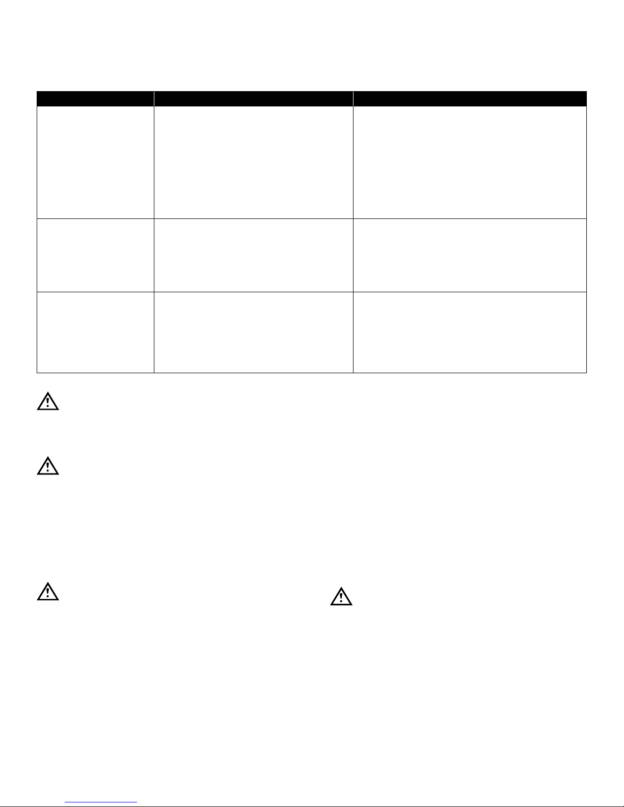
GENERAL TROUBLSHOOTING GUIDE
PROBLEM PROBABLE CAUSE REMEDY
COOKING INDICATOR
LIGHT FAILS TO LIGHT
WITH TIMER SET
STEAM FAILS TO ENTER
COOKING COMPARTMENT
WITH COOKING INDICATOR
LIGHT ON
STEAM ENTERS COMPARTMENT CONTINUOUSLY
WITHOUT THE COOKING
OR READY LIGHT ON
a. Main power circuit breaker
tripped.
b. Door interlock switch contacts not
closed.
c. Door interlock switch faulty.
d. Indicator light burned out.
e. Faulty timer contacts.
f. Faulty wiring.
a. Faulty wiring. a. Inspect condition of wire and
a. Standby thermostat not set cor-
rectly.
b. Faulty thermostatic switch.
c. HOLD set on timer.
a. Locate external circuit breaker for
incoming power and place in ON
position.
b. Shut cooker door to close switch
contacts. Check alignment of door
with switch.
c. Replace switch.
d. Replace light.
e. Replace timer.
f. Inspect condition of wire and
tightness of all connections. Correct
as needed.
tightness of all connections. Correct
as needed.
a. Adjust the thermostat lower.
b. Replace thermostat.
c. Rotate timer knob to ‘OFF’ position.
TIMER DIAL NOT TURNING a. Faulty timer motor.
b. Faulty wiring.
BUZZER FAILS TO SOUND
AT END OF TIMER SETTING
STEAM FLOWS CONTINUOUSLY FROM DRAIN LINE
WITH COOKER IN OPERATION
a. Timer contacts faulty.
b. Buzzer faulty.
c. Faulty wiring.
a. Cold water not connected.
b. Faulty cooling valve.
c. Faulty wiring.
a. Replace timer.
b. Inspect condition of wire and light-
ness of all connections. Correct as
needed.
a. Replace timer.
b. Replace buzzer.
c. Inspect condition of wire and tight-
ness of all connections. Correct as
needed.
a. Turn on external shutoff valve.
b. Replace cooling valve.
c. Inspect condition of wire and
tightness of all connections. Correct
as needed.
Page 4

GENERAL TROUBLSHOOTING GUIDE
PROBLEM PROBABLE CAUSE REMEDY
DOOR LEAKS. a. Damaged door gasket.
b. Clogged compartment drain.
WATER FLOWS INTO
COOKING COMPARTMENT.
NOTE: THESE PROBLEMS ARE AN INDICATION OF SEVERE WATER CONDITIONS WHICH SHOULD BE COR-
RECTED IMMEDIATELY TO AVOID DAMAGE TO THE COMPONENTS AND PERFORMANCE OF THE
STEAMER. CALL YOUR SERVICE AGENCY FOR ASSISTANCE.
WATER ACCUMULATES IN
COMPARTMENT.
WATER FLOWS INTO DRAIN
DURING SHUTDOWN.
WATER NOT BEING SUPPLIED TO GENERATOR.
a. Level control has failed.
b. Water has very high resistance
c. Scale build-up on probe.
d. Water ll solenoid valve.
a. Plugged compartment drain a. Remove screen and clean drain
a. Cooling valve does not close. a. Check valve for foreign material or
a. Water supply off.
b. Supply water pressure too low.
a. Check gasket for cuts and replace.
b. Remove screen and clean drain line
or plumbing.
a. Replace.
b. Replace level control with high sen-
sitivity control.
c. Clean all probes
d. Plugged, defective, clean or re-
place.
line.
damage.
a. Check incoming water valve is on.
b. Call supply agency.
c. Defective water solenoid valve.
d. Level Probe shorted.
e. Defective water level control.
f. Drain valve is open.
c. Replace or clean.
d. Check and correct.
e. Replace.
f. Check valve, clean or replace.
Page 5

ELECTRICAL FAULT ISOLATION GUIDE
FAILURE FAULT LOCATION
1. WILL NOT OPERATE IN EITHER HOLD OR 60-MINUTE TIMER POSITIONS.
2. OPERATING IN HOLD POSITION BUT NOT IN 60-MINUTE TIMER
POSITION.
3. OPERATES IN 60-MINUTE TIMER POSITION BUT NOT IN HOLD POSITION.
4. WITH COOK INDICATOR LIGHT ON AND STEAM ENTERING THE
CAVITY, TIMER DIAL FAILS TO TURN.
5. BUZZER FAILS TO SOUND AT END OF 60-MINUTE TIMER MODE. a. 60-Minute timer contacts
a. Incoming power
b. Timer
c. Door interlock switch
d. Wiring
a. 60-Minute timer
b. Wiring
a. Timer
b. Wiring
c. Hold thermostat
a. Hold position set on timer.
b. Timer motor
c. Wiring
b. Buzzer
c. Wiring
6. STEAM FLOWS CONTINUOUSLY FROM BOILER DRAIN LINE. a. Cooling valve needs replacing
b. Wiring
Page 6

TROUBLESHOOTING
60 MINUTE TIMER
Timer Contacts
Defective timer contacts will result in failure of cooker
compartment to operate.
When this occurs, remove the side panel and proceed as
follows:
1. Turn off power to the cooker at external circuit breaker
2. Disconnect all ve wires from timer terminals.
3. Connect an ohmmeter between terminals 1 and 3.
4. Rotate timer dial beyond the “0 - Minute” point (any
setting) to obtain a reading of zero ohms on the ohmmeter. If zero ohm reading cannot be obtained, timer
contacts are defective and the timer must be replaced.
5. Move ohmmeter leads to terminals 1 and 4.
6. Rotate timer dial to “0 - Minute” position (an audible
click indicates correct position). If zero ohm reading
cannot be obtained, the timer is defective and must
be replaced.
7. Remove ohmmeter and replace all ve leads on timer
terminals.
Timer Motor
A defective timer motor will cause continuous operation in
the TIME mode, with the timer dial failing to return to the
“0 - Minute” position.
To conrm timer motor condition, proceed as follows:
1. Carefully check motor wire leads and tighten loose
connections
WARNING
Use care while working with control panel.
Terminals carry 120 Volts.
2. Turn on power to the steamer.
3. Set timer dial (any setting beyond “0 - Minute”). If operation is correct, the motor will turn the dial toward
“0 - Minute”. If the motor fails to operate, it is defective
and the entire timer must be replaced.
DOOR INTERLOCK SWITCH
Malfunction of the cooker door interlock switch prevents
indicator lights from turning on and steam generator from
operating when the timer dial is set. If steam does not
enter the compartment and the cooking indicator light fails
to turn on with the door latch securely engaged, the fault
may be in the door interlock switch. Proceed as follows:
1. Turn off power to the cooker.
2. Disconnect wires to the door switch terminals.
3. Connect an ohmmeter between the Common & N.O.
(Normally Open) terminals of the switch.
4. Actuate the switch by closing the cooking compartment door. If a zero reading cannot be obtained, the
switch is defective and must be replaced.
5. Remove the ohmmeter and replace the leads on
switch terminals.
INDICATOR LIGHTS
If the cooker compartment functions correctly, with the
single exception that the indicator light fails to light during
operation, the fault is a defective indicator light. A “burned
out” or defective light is veried by using an AC volt-meter
at the leads, with input power on the selector switch in the
correct position for that timer, the timer set, and the door
latches closed. If 120 volts is present, the fault is in the indicator light and requires replacement. If 120 volts is not
present, the fault is in the wiring or control components
(selector switch, timer or door switch).
BUZZER
If the buzzer does not sound at the termination of the
operator-selected timer setting (timer dial returned to “0
- Minute” position), the fault may be a defective buzzer.
Buzzer operation is veried using an AC volt-meter at
buzzer coil connections with input power on and selector switch and coinciding timer dial set at the “0 - Minute”
position. If voltage is 120 volts, the fault is in the buzzer,
which must be replaced. If 120 volts is not present, the
fault is in the wiring or control components (timer or selector switch).
4. Shut off power to the cooker.
WIRING
Using an ohmmeter, wiring continuity between the con-
nections shown on the wiring diagram is readily veried.
This is best done in stages, removing only those wires
required for each continuity check. As each lead is replaced, it should be checked for evidence of corrosion,
and cleaned if necessary. All leads must be tightly attached so as to provide a good electrical connection.
Page 7
ADJUSTMENTS
All units are adjusted at the factory. In case of operation problems at initial installation, check type of gas supply and manifold pressure and compare it with information on the rating plate.
PROBLEM PROBABLE CAUSE REMEDY
BURNERS DO NOT
COME ON
BURNERS PRODUCE CARBON
DEPOSITS
FLASH BACK a. Burning inside mixer tube.
WARNING
At least twice a year, have an authorized
service person clean and adjust the unit for
maximum performance.
WARNING
Adjustments and service work may be per-
formed only by a qualied technician who is
experienced in, and knowledgeable with the
operation of Commercial Gas Cooking Equip-
ment. However, to assure your condence,
contact your authorized service agency for
reliable service, dependable advice or other
assistance and for genuine factory parts.
a. Gas supply is off.
b. Power switch is off.
c. Probe not sensing water level.
d. Ignitor not functioning.
e. Combination gas valve not opening.
a. Incorrect orice size.
b. Incorrect gas supply.
c. Incorrect gas pressure.
b. Incomplete combustion.
c. Sooting of burner.
d. Mislocated ignitor.
a. Locate supply line and turn on.
b. Locate switch on control panel and turn on.
c. Clean probes, check wiring.
d. Check ignition module, relay.
e. Check that control knob is in the ON posi-
tion, check that 24 volts is at the gas valve.
a. Check size and correct.
b. Check size and correct.
c. Check gas pressure at manifold. Correct if
necessary.
a. Reduce primary air.
b. Increase burner input.
c. Increase primary air.
d. Adjust ignitor.
door panel assembly.
4. Remove the gasket plate and the door gasket from
door panel.
5. Install the new door gasket to the door panel. Replace the gasket plate and six screws.
6. Reassemble the door panel assembly in the door
frame using the four screws.
7. Gasket replacement is now complete.
Door may be difcult to close until gasket has compressed
to conform to opening. Leaving door closed overnight will
compress gasket.
EXTERIOR PANEL REMOVAL
CAUTION
Shut off main electrical power to unit.
DOOR GASKET REPLACEMENT
The cooking compartment door gaskets are made of a
silicone-type rubber material that is very durable but subject to wear during normal operation. Should the gasket
leak replace it.
1. Open the cooking compartment door.
2. Remove the four screws on the outside of the door
frame, and remove the door panel assembly.
3. Remove the six screws from the gasket plate in the
WARNING
To prevent hazard in servicing the cooker, be
certain that the steam supply boiler is shut
down, the cold water shut-off valve is closed,
and the electrical disconnect circuit breaker
for the Cooker/Boiler unit is OFF before removing side panels.
Access to all internal plumbing and electrical assemblies
is from the right side. The right-side panel is removed by
removing the bottom screws from panel. Gas controls are
located in the lower cabinet and are accessible from the
front of the unit.
Page 8

WIRING DIAGRAMS
Page 9

WIRING DIAGRAMS
Page 10

WIRING DIAGRAMS
Page 11

WIRING DIAGRAMS
Page 12

WIRING DIAGRAMS
ITEM PART NO. DESCRIPTION
1 A 4-22TB Terminal Block 2 2
1 B 4-22ES Terminal Block End 1 1
2 9124-2 Switch, On/Off/Delime 2 1
3 4874-1 Thermostat, High Limit Safety 2 1
** 4 4038-4 Level Control, 10K OHM 2 1
5230-1 Level Control, 1M OHM 4 2
5 3738-9 Probe, Low Level Cut-Off 2 1
6 3738-8 Probe, Low Level 2 1
7 3738-7 Probe, High Level 2 1
8 4-PL04 Ready Pilot, Green, 125V 2 1
9 9126-1 Thermostat, Operating 2 1
10 9-3213 Door Switch 2 1
11 9-3174-1 Relay, DPDT 4 2
12 08-6464 Timer, 60 Min. 2 1
13 3821-1 Buzzer 2 1
14 4-PL07 Cooking Pilot, Red, 125V 2 1
15 9-3383 Transformer, 120-24V 2 1
16 5162-1 Fill Solenoid Valve 3 2
17 3-S543 Drain Valve 3 2
18 9210-1 Ignition Module 2 1
19 5362-1 Spark/Sensor Probe 2 1
** 20 9092-1 Fuse, 1A, 250V, (220V) 2 1
9092-2 Fuse, 2A, 250V, (120V) 2 1
21 9068-1 Fuse Holder 2 1
22 9-3175-1 Relay, SPDT 2 1
** 23 5450-1 Gas Valve, Natural 2 1
** 23 5450-2 Gas Valve, Liquid Propane 2 1
24 08-6502 Pressure Switch, Operating 2 1
25 9242-1 Time Delay Relay, Operating 2 1
26 08-6588 Hold Thermostat 2 1
27 08-5023 Float Switch 1 1
28 08-6514 Tank Thermostat, C130EF 1 1
29 9224-1 Time Delay Relay, Cooling 1 1
30 4-PL04-2 Ignition Pilot, Green, 24V 2 1
31 98-4206 Power Supply, 120V - 5VDC 1 1
32 9344-1 Relay, DPDT, 120 VAC 2 1
33 4-T265 Transformer, 208-240/120V 2 1
** SELECT AS REQUIRED.
QUANTITY
1 COMP 2 COMP
Page 13

STEAMER EXPLODED VIEW
JUNE 12, 2015 13 ETP-5G & ETP-10G
Page 14

STEAMER EXPLODED VIEW
ITEM PART NO. DESCRIPTION EPT-5G EPT-10G
1 97-6334 Compartment Strainer 1 2
2 97-6177 Perforated Trough 1 1
3 97-6175 Pan Rack 2 4
4 97-6174 Hinge Rod 1
4 97-6269 Hinge Rod 1
5 97-6191 Door Switch 1 2
97-6429 Switch Actuator 1 2
6 97-6178 Striker 1 2
7 97-6554 Control Panel Decal 1
7 97-6430 Control Panel Decal 1
8 97-6170 Ready Pilot Light, Green, 125V 1 2
9 97-5472 Ignition Pilot Light, Green, 28V 1 2
10 97-6171 Pilot Light, Red, 125V 1 2
11 08-3826 Knob 1 2
12 97-6367 Switch, On/Off/Delime 1 2
13 08-7521 Temperature Indicator 1 2
91-6491 Grommet 1 2
14 97-6227 Outer Door Shell 1 2
15 97-6432 Door Handle Assembly 1 2
16 97-6232 Latch Assembly 1 2
17 97-6236 Spacer 2 3
18 97-6261 Bushing 4 8
19 97-6230 Door Panel 1 2
20 97-6228 Door Gasket 1 2
21 97-6229 Gasket Retaining Plate 1 2
22 97-6233 Gasket Panel Screws 8 16
23 97-6481 Hose Clamp, 5/8" 10 20
** 24 97-6434 Hose, 5/8 I.D. x 30" Long, Upper Generator Drain 1
97-6435 Hose, 5/8 I.D. x 12" Long, Lower Generator Drain 1
Hose, 5/8 I.D. x 14" Long, Lower Generator Drain 1
25 97-6436 Brass Elbow, 5/8"C x 3/4" MPT 1 2
26 97-5946 Blowdown Solenoid Valve 1 2
27 97-6209 Connector, 5/8" C x 3/4" MPT 1 2
28 97-6555 Right Side Panel 1
28 97-6437 Right Side Panel 1
* NOT SHOWN ** SELECT AS REQUIRED *** CONTACT FACTORY
JUNE 12, 2015 14 ETP-5G & ETP-10G
Page 15

STEAMER EXPLODED VIEW
ITEM PART NO. DESCRIPTION EPT-5G EPT-10G
** 29 97-6438 Hose, 5/8" I.D. x 34" Long, Upper Cavity Drain 1
97-6439 Hose, 5/8" I.D. x 16" Long, Lower Cavity Drain 1
30 97-6440 Brass Tee, 3/8"C 1
31 97-6188 Brass Elbow, 3/8"C x 1/8" MPT 2 3
32 98-6123 Brass Connector, 1/4 C x 1/8" MPT 2 4
33 97-6441 Timer Delay Relay, Cooling - 120V 1 1
97-6581 Timer Delay Relay, Cooling - 240V 1 1
34 97-6186 Fuse, 2A, 250V 1 2
35 97-5864 Fuse Holder 1 2
36 10-6962 End Section, Terminal Block 1 1
37 10-6963 Terminal Block 2 2
38 97-5441 Ground Lug 1 1
39 97-6282 Solenoid Valve 2 3
40 97-5991 Relay, DPDT, 120V 2 4
41 97-6344 Connector, 3/8 C x 1/8" MPT 1 1
42 97-6442 Bulkhead Union, 3/8"C 2 2
43 97-6443 Hose Clamp, 1-1/16 - 2" 2 4
44 97-6444 Drain Hose, 1-1/4" x 1-3/4" Long 2 2
45 97-6445 Drain Tube Assembly 1 2
46 97-5702 Cord Set, 120V 1 1
47 97-6418 Generator Tank, Lower 1
48 97-6419 High Limit Thermostat 1 2
** 49 97-5948 Liquid Level Control, 10K OHM 1 2
Liquid Level Control, 1M OHM (Optional) 1 4
50 97-5701 Transformer, 120-24V 1 2
51 97-5048 Standby Thermostat 1 2
52 97-5572 Ignition Module 1 2
53 97-5992 Relay SPDT, 120V 1 2
54 97-6190 Buzzer 1 2
55 97-6420 Brass Street Elbow, 3/8" FPT x 1/4" MPT 2 4
56 97-6421 Brass Hose Barb, 5/8" x 3/8" MPT 2 4
57 97-6422 Brass Hose Barb, 5/8" x 1/2" MPT 1 2
58 97-6423 Steam Diverter Hose, 5/8 I.D. x O.D. x 11-1/4" LG. 2 4
59 08-6464 Timer, 60 Minutes, 120V 1 2
** 60 97-6424 Upper Delime Hose, 5/8" I.D. x 22" Long 1 1
* NOT SHOWN ** SELECT AS REQUIRED *** CONTACT FACTORY
JUNE 12, 2015 15 ETP-5G & ETP-10G
Page 16

STEAMER EXPLODED VIEW
ITEM PART NO. DESCRIPTION EPT-5G EPT-10G
97-6425 Lower Delime Hose, 5/8" I.D. x 37" Long 1
61 97-6426 Brass Hose Barb, 5/8" x 3/4" MPT 1 2
62 97-6203 Brass Tee, 3/4" 1 2
63 97-6204 Brass Close Nipple, 3/4" 1 2
64 97-6202 Brass Elbow, 3/4" 1 2
65 97-6368 Relief Valve Extension 1 2
66 97-6427 Top Panel 1
66 97-6560 Top Panel 1
67 97-6428 Brass Nipple, 3/4" x 5-1/2" 1 2
68 97-6219 Relief Valve, 5 PSI 1 2
69 91-7594 Reducing Elbow Assembly 1 2
91-7765 Clean Port Plug 1 2
69 08-7511 “O” Ring 1 2
70 97-6372 Probe - High Level 1 2
71 97-6213 Probe - Low Level 1 2
72 97-6212 Probe - Low Level Cut Off 1 2
73 08-6502 Pressure Switch 1 2
74 97-6559 Generator Tank, Top 1 1
75 97-6446 Tubing, Pressure Switch, 1/4" I.D. x 8" Long 1 2
76 97-6447 Brass Hose Barb, 1/4" x 1/8 MPT 2 4
77 97-6448 Pressure Switch Bracket 1 2
78 08-5015 Vacuum Breaker 1 2
79 97-6449 Tubing, Vacuum Break, 1/4" I.D. x 2" Long 1 2
80 97-6450 Brass Extruded Street Tee, 1/8" FPT 1 2
82 97-6452 Brass Bushing, NPT, 1/4" to 1/8" 1 2
83 97-6453 Brass Bushing, NPT,1/2" to 1/4" 1 2
84 97-6454 Brass Locknut, 1/2" NPT 1 2
85 10-4586 Sealing Nut, 1/2" NPT 1 2
86 97-6455 Timer Delay Relay, Operating - 120V 1 2
97-6455 Timer Delay Relay, Operating - 240V (EXPORT) 1 2
* NOT SHOWN ** SELECT AS REQUIRED *** CONTACT FACTORY
JUNE 12, 2015 16 ETP-5G & ETP-10G
Page 17

GAS COMPONENTS
JUNE 12, 2015 17 ETP-5G & ETP-10G
Page 18

GAS COMPONENTS
ITEM PART NO. DESCRIPTION EPT-5G EPT-10G
1. 97-6463 Upper Gas Flex Tube, 5/8", O.D. x 42" Long. 1
2. 97-6457 Gas Supply Pipe Assembly 1 1
3. 97-6458 Bracket 1 1
4. 97-6459 Malleable Iron Tee, 3/4" x 3/4" x 1/2" 1
5. 97-6460 Nipple, 3/4" x 2" Long 1
6. 97-5555 90º Reducing Elbow, 3/4" NPT x 1/2" NPT 1 1
** 7. 97-6461 Gas Valve, Natural Gas 1 2
94-5128 Gas Conversion Kit, Natural to LP 1 2
97-6462 Gas Valve, LP Gas 1 2
94-5131 Gas Conversion Kit, LP to Natural 1 2
8. 98-6109 Close Nipple, 1/2" 1 2
9. 98-6122 Union Elbow, 1/2" 1 2
10 97-6532 Lower Gas Flex Tube, 5/8" O.D. x 24" Long 1 1
11 97-6464 Hex Screw, 8 - 32 x 1/4" 4 8
** 12 97-6244 Pilot Burner, LP Gas 1 2
97-6465 Pilot Burner, Natural Gas 1 2
13 97-6245 Burner Mounting Bracket 1 2
14 97-6466 Machine Screw, 10 - 32 x 3/8" 2 4
15 97-6467 Machine Screw, 10 - 32 x 1/4" 2 4
16 97-6242 Spark Electrode 2
** 17 97-6468 Pilot Tube - Top 1
97-6469 Pilot Tube - Bottom 1
97-6533 Pilot Tube 1
18 97-6470 Machine Bolt, 1/4 - 20 x 1/2" 2 4
19 98-6124 Plug, 1/8" NPT 1 2
** 20 97-6247 Manifold, Natural Gas 1 2
** 20 97-6534 Manifold, LP Gas 1 2
* 21 97-6498 Orice, #53, Natural Gas 4 8
97-6535 Orice, #64, LP Gas 4 8
** 22 97-6246 Twin Burners, Natural Gas 2 4
97-6536 Twin Burners, LP Gas 2 4
** 23 97-6472 Screw, #6 x 3/8", (Natural Gas Only) 4 8
* NOT SHOWN ** SELECT AS REQUIRED
JUNE 12, 2015 18 ETP-5G & ETP-10G
Page 19

CABINET ASSEMBLY
1
2
3
20
24
23
22
21
17
19
18
12
13
12
5
6
41
16
15
5
12
45
43
10
4
5
6
7
14
8
9
7
5
6
11
12
13A
26
12
25
44
42
JUNE 12, 2015 19 ETP-5G & ETP-10G
38
28
39
29
31
31
13A
12
5
6
37
36
34A
4640
47
27
32
30
35
34
33
48
Page 20

CABINET ASSEMBLY
ITEM PART NO. DESCRIPTION EPT-5G EPT-10G
** 1 97-6537 Hinge Rod 1
97-6473 Hinge Rod 1
** 2 97-6538 Cabinet Door Assembly 1
97-6539 Cabinet Door Assembly 1
3 ~NPN~ Flat Washer 1 1
4 98-3784 Tempering Tank 1 1
5 97-6421 Brass Hose Barb, 5/8" x 3/8" MPT 5 7
6 97-6476 Brass Extruded, 90° Street Elbow, 3/8" 4 6
7 ~NPN~ Brass Square Head Plug, 3/8" 2
8 08-5023 Float Switch 1 1
9 97-6477 Hex Nipple, 3/4" MPT x 1/2" MPT 1 1
10 97-6210 Drain Valve, Tank 1 1
11 97-6436 Brass Elbow, 90°, 5/8" C x 3/4 MPT 1 1
12 97-6422 Hose Clamp, 5/8 - 1-1/4" 1
** 13 97-6439 Hose, 5/8" I.D. x 16" Long 1
97-6480 Hose, 5/8" I.D. x 14" Long 1
13A 97-6480 Hose, 5/8" I.D. x 14" Long 1 1
14 08-6514 Tank Thermostat, 130°F 1 1
15 97-6482 Brass Bushing, 1/2" MPT to 3/8" FPT 1 1
16 97-6483 Brass Elbow, 90°, 5/8" C x 1/2" FPT 1 1
17 97-6346 Brass Elbow, 90°, 3/8" C x 3/8" MPT 1 1
18 97-6484 Vent 1 1
** 19 97-6486 Flanged Foot 2 2
* 97-6406 Swivel Caster, 5", c/w Brake, Optional 2 2
** 20 97-6486 Adjustable Flanged Foot 2 2
97-6561 Swivel Caster, 5", Optional 2 2
21 97-6487 Pan Slot Head Screws, #6-32 UNC x 3/8" Long 4 4
22 97-6488 Spring Lock Washer, #6 4 4
23 97-6489 Magnetic Catch 1 1
24 97-6490 Magnetic Catch Plate 1 1
25 08-8055 Filter Head 1 1
26 97-6541 Elbow, 3/8" C to 3/8" MPT, Nylon 1 1
27 97-6542 Bushing, 3/4" to 3/8", Nylon 1 1
28 08-8061 Bushing, 3/4" to 1/2", Nylon 1 1
29 08-8057 Te e 1 1
JUNE 12, 2015 20 ETP-5G & ETP-10G
Page 21

CABINET ASSEMBLY
ITEM PART NO. DESCRIPTION EPT-5G EPT-10G
30 08-8064 Elbow, 3/4" Nylon 1 1
31 08-8062 Nipple, Reducing, 3/4" x 1/2 NPT, Nylon 2 2
32 08-8053 Check Valve, Nylon 1 1
33 97-6547 Connector, 3/8" C to 3/8" MPT, Nylon 1 1
34 97-6548 Tubing, 3/8" O.D., x 18" Long, Nylon 1
~NPN~ Tubing, 3/8" O.D. x 19" Long, Nylon 1
34A ~NPN~ Tubing, 3/8" O.D. x 30" Long, Nylon 1 1
35 97-6549 Sleeve, 3/8", Brass 2 2
36 97-6550 Connector, 3/8" C to 3/8" Nylon 1 1
37 ~NPN~ Tubing, 3/8" O.D. x 8" Long, Copper 1 1
38 08-8020 Filter, Large (See Item 42). 1 1
39 08-8008 Filter, Small, Scale Inhibitor (See Item 42) 1 1
40 08-8007 Meter 2%6
41 97-6411 Drain Collector 1 1
* 42 08-8052 * Kit, Filter Replacement Cartridges 1 1
** 43 7844-1 Lower Cabinet Shield 1
7844-2 Lower Cabinet Shield 1
44 08-8059 Pressure Gauge 1 1
45 7845-1 Mounting Bracket 1 1
* 46 Adapter Cord
* 47 98-4206 Power Supply, 120/240 VAC - 5 VDC 1 1
48 ~NPN~ Mounting Plate (Cuno Filter Head VH3) 1 1
* NOT SHOWN ** SELECT AS REQUIRED
JUNE 12, 2015 21 ETP-5G & ETP-10G
 Loading...