

Market Forge Industries DFFG-50 Owner's Manual
0
OWNER’S MANUAL
WARNING:
IMPROPER INSTALLATION, ADJUSTMENT,
ALTERATION, SERVICE OR MAINTENANCE CAN
CAUSE PROPERTY DAMAGE, INJURY OR DEATH.
READ THESE INSTALLATION, OPERATION AND
MAINTENANCE INSTRUCTIONS THOROUGHLY
BEFORE INSTALLING OR SERVICING THIS
EQUIPMENT.
FOR YOUR SAFETY:
DO NOT STORE OR USE GASOLINE OR OTHER
FLAMMABLE VAPORS OR LIQUIDS IN THE VICINITY
OF THIS OR ANY OTHER APPLIANCE.
Form Number: S-6104 REV: A 09/13
Printed in USA 35 Garvey Street, Everett, MA 02149
Telephone (617) 387-4100, (866) 698-3188, Fax (617) 387-4456, (800) 227-2659
custserv@mfii.com, www.mfii.com
CAUTION:
INSTRICTIONS TO BE FOLLOWED IN THE EVENT
THE USER SMELLS GAS SHALL BE POSTED IN A
PROMINENT LOCATION. THIS INFORMATION
SHALL BE OBTAINED BY CONSULTING THE LOCAL
GAS SUPPLIER.
IMPORTANT:
MUST ORDER REINFORCEMENT CHANNELS IF
MOUNTING TO OVEN OR RANGE.
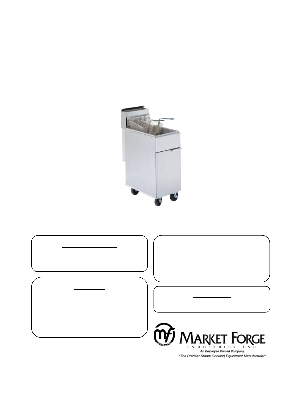
Heavy Duty Gas Tube Fryer
Model: □ DFFG-50
INSTALLATION, OPERATION, MAINTENANCE, SERVICE & PARTS LIST

1
Table of Contents
INTRODUCTION .............................................................................................................................. 2
Important Information: ............................................................................................................... 2
Shipping Damage Claim Procedure: ............................................................................................ 2
Visible loss or damage: ........................................................................................................... 2
File claim for damages immediately: ...................................................................................... 2
Concealed loss or damage: ..................................................................................................... 2
Service: ........................................................................................................................................ 2
Air Supply and Ventilation:.......................................................................................................... 2
Flex Coupling, Connectors and Casters:.................................................................................. 3
Disclaimer: ................................................................................................................................... 3
INSTALLATION ................................................................................................................................ 4
READ BEFORE INSTALLING .......................................................................................................... 4
Clearance: ............................................................................................................................... 4
Rating Plate: ............................................................................................................................ 4
Gas Connection: ...................................................................................................................... 4
Manual Shut-Off Valve: ........................................................................................................... 4
Pressure Regulator: ................................................................................................................. 4
Dimensions:............................................................................................................................. 5
Connections: ........................................................................................................................... 5
Specifications: ............................................................................................................................. 5
50 lb. Tube Fryer ..................................................................................................................... 5
OPERATION ..................................................................................................................................... 6
Preparation Before use: .............................................................................................................. 6
Before Turning the Burners On: .............................................................................................. 6
LIGHTING INSTRUCTIONS: ........................................................................................................... 6
Burners/Thermostat Operation: ............................................................................................. 6
Pilot Operation: ....................................................................................................................... 7
Main Burner Operation: .......................................................................................................... 7
DAILY SHUT DOWN: .................................................................................................................... 7
MAINTENANCE ............................................................................................................................... 8
Cleaning: ................................................................................................................................. 8
Daily Cleaning: ......................................................................................................................... 8
Weekly Cleaning: .................................................................................................................... 8
Cleaning Stainless Steel: ......................................................................................................... 9
ILLUSTRATED PARTS ..................................................................................................................... 10
Fryer Exploded View ............................................................................................................. 10
Fryer Parts List ...................................................................................................................... 11

2
INTRODUCTION
Installation of the equipment should be performed by qualified, certified and authorized personal who
are familiar and experienced with local installation codes.
Before installation please red instructions completely and carefully.
Do not remove permanently affixed labels, warnings or plates from unit.
Important Information:
The installation must conform with local codes, or in the absence of local codes, to the national fuel gas
code, ANSIZ223.1-1988 (or latest addenda), national gas installation code, CAN/CGA-B 149,1, or the
propane installation code, CAN/CGA-B 149.2 as applicable.
The appliance and its individual shut off valve must be disconnected from the gas supply piping system
during any pressure testing of that system in excess of 1/2 PSI.
The gas supply line must be at least the same size as the inlet of the appliance.
Shipping Damage Claim Procedure:
The equipment is crafted and inspected carefully by skilled personnel before leaving the factory. The
transportation company assumes full responsibility for safe delivery upon acceptance of this equipment.
If shipment arrives damaged:
Visible loss or damage:
Note the damage or loss on freight bill or express delivery and signed by the person making the delivery.
File claim for damages immediately:
Regardless of the extent of damages.
Concealed loss or damage:
If damage is noticed after unpacking, notify the transportation company immediately and file a
"Concealed Damage" claim with them. This should be done within fifteen (15) days from the date
delivered. Retain container for inspection.
Service:
Installation & Service of the equipment should be performed by qualified, certified, licensed and/or
authorized personnel who are familiar with and experienced in state/local installation codes.
Operation of the equipment should be performed by qualified and authorized personnel who have read
this manual and are familiar with the functions of the equipment.
Air Supply and Ventilation:
For proper operation of the appliance, do not obstruct the flow of combustion and ventilation air.
The area in front of, around and above the appliance must be kept clear to avoid any obstruction of the
flow of combustion and ventilation air. Adequate clearance must be maintained at all times in front and
at the sides of the appliances for servicing and proper operation.

3
Means must be provided for any commercial, heavy-duty cooking appliance to exhaust combustion
waste products to the outside of the building. Usual practice is to place the unit under an exhaust hood.
Filters and drip troughs should be part of any industrial hood. Consult local codes before constructing
and installing a hood.
Strong exhaust fans in this hood or in the overall air conditioning system can produce a slight vacuum in
the room and/or cause air drafts, either of which can interfere with pilot or burner performance and can
also be hard to diagnose. Air movement should be checked during installation; if pilot or burner outage
problems persist, make-up air openings or baffles may have to be provided in the room.
Flex Coupling, Connectors and Casters:
If the unit is to be installed with casters, the installation shall be made with a connector that complies
with the Standard for Connectors for Movable Gas Appliances, ANSI Z21.69 or Connectors for Moveable
Gas Appliances, CAN/CGA-6.16, and a quick-disconnect device that complies with the Standard or QuickDisconnect Devices for Use With Gas Fuel, ANSI Z21.41, or Quick Disconnect Devices For Use with Gas
Fuel CAN1-6.9. Locking front casters are provided to limit the movement of the appliances without
depending on the connector or associated piping. A suitable strain relief must be installed with the
flexible connector.
Restraining device may be attached to the back frame/panel of the unit.
All connections must be sealed with a joint compound suitable for LP gas and all connections must be
tested with a soapy water solution before lighting pilots.
Disclaimer:
All MARKET FORGE INDUSTRIES, INC. appliances are adjusted and tested before leaving the factory,
effectively matching them to sea level conditions. Adjustments and calibrations to assure proper
operation may be necessary on installation to meet local conditions; low gas characteristics, to correct
possible problems caused by rough handling or vibration during shipment, and are to be performed only
by qualified service personnel. These adjustments are the responsibility of the customer and/or dealer
and are not covered by our warranty.
 Loading...