

Market Forge Industries CAPELLA - 4, CAPELLA 10, CAPELLA 8, CAPELLA 12, CAPELLA 6 Owner's Manual

OWNER’S MANUAL
CAPELLA STEAMER
MODELS:
INSTALLATION
OPERATION
MAINTENANCE
STEAM COOKING
GUIDELINES
PARTS LISTS
PARTS & SERVICE
CAPELLA - 4 CAPELLA - 8
CAPELLA - 6 CAPELLA - 10
CAPELLA - 12
35 Garvey Street, Everett, MA 02149:
Tel: (617) 387-4100
Fax: (617) 387-4458
custserv@mfii.com, www.mfii.com
1/2012 5(9 % )250 12 6

TABLE OF CONTENTS
IMPORTANT NOTES FOR SAFETY, INSTALLATION AND OPERATION ............................................... 4
A. INTRODUCTION ............................................................................................................................ 5
1) Product Description .......................................................................................................... 5
2) Safety Features ................................................................................................................. 5
3) Dimensions ....................................................................................................................... 5
4) Service Contacts ................................................................................................................ 6
B. SERVICE CONNECTIONS ................................................................................................................ 7
C. INSTALLATION ............................................................................................................................... 9
D. START UP PROCEDURE.................................................................................................................. 10
E. OPERATION .................................................................................................................................... 10
F. CLEANING GUIDELINES .................................................................................................................. 12
A. Daily Cleaning ................................................................................................................... 12
B. Monthly Cleaning .............................................................................................................. 12
G. STEAM COOKING GUIDELINES ...................................................................................................... 14
A. Cooking with atmospheric/pressureless steam ............................................................... 14
B. Recommended uses .......................................................................................................... 14
C. Typical foods ..................................................................................................................... 14
D. Tips on cooking frozen product ........................................................................................ 14
E. Blanching ........................................................................................................................... 14
F. Tips on pan use.................................................................................................................. 14
G. Other helpful hints ........................................................................................................... 15
H. WARINGS AND CAUTIONS ............................................................................................................ 15
A. Warnings ........................................................................................................................... 15
B. Cautions ............................................................................................................................ 16
I. WIRING DIAGRAMS ........................................................................................................................ 17
A. 208/240 Volts ................................................................................................................... 17
Figure 1 .................................................................................................................... 17
B. 480 Volts .......................................................................................................................... 18
Figure 2 .................................................................................................................... 18
J. ILLUSTRATED PARTS LIST ............................................................................................................... 19
1. Cabinet assembly .............................................................................................................. 19
Figure 3 .................................................................................................................... 19
Figure 4 .................................................................................................................... 19
Figure 5 .................................................................................................................... 20
Figure 6 .................................................................................................................... 20
2. Door assembly................................................................................................................... 21
Figure 7 .................................................................................................................... 21
Figure 8 .................................................................................................................... 21
3. General assembly .............................................................................................................. 22
Figure 9 .................................................................................................................... 22
Figure 10 .................................................................................................................. 23
Figure 11 .................................................................................................................. 23
4. Control panel components ............................................................................................... 24
Figure 12 .................................................................................................................. 24
Figure 13 .................................................................................................................. 24
Figure 14 .................................................................................................................. 25
Figure 15 .................................................................................................................. 26
Figure 16 .................................................................................................................. 26
Figure 17 .................................................................................................................. 27
5. Convection Fan and Motor Components .......................................................................... 28
Figure 18 .................................................................................................................. 28
Figure 19 .................................................................................................................. 28
IMPORTANT NOTES FOR SAFETY, INSTALLATION AND OPERATION
WARNING: This is the safety alert symbol. It is used to alert you to potential
!
!
personal injury hazards. Obey all safety messages that follow this symbol to
avoid possible injury or death.
WARNING: Improper installation adjustment, alteration, service or
maintenance can cause property damage, injury or death. Read the
installation, operating and maintenance instructions thoroughly before
installing or servicing this equipment.
!
!
!
It is recommended that this manual be read thoroughly and that all instructions be
followed carefully.
WARNING: Never spray water into electrical components.
WARNING: Do not store or use gasoline or other flammable vapors or liquids
in the vicinity of this or any other appliance.
WARNING: Please make certain that every operator of this piece of
equipment has been instructed on its proper and safe use, and has read and
understands all warnings, cautions, and notes in this manual.
This manual should be retained for future reference.
Intended for commercial use only. Not for household use.
4

A INTRODUCTION
1) Product Description:
Congratulations on purchasing the Market Forge Capella. The Capella is a single compartment
countertop or two-compartment floor model steamer featuring pressureless steam cooking and a
circulating fan inside the cooking chamber to speed cooking. The cooking chamber of the Capella
is treated with a scratch resistant, non-stick surface. A low water probe prevents the steamer from
running dry an a ball valve drain is provided for easy safe draining.
CAUTION: Do not use utensils, steel wool, or other harsh abrasives to clean your steamer.
Scratching of the non-stick surface and stainless steel casing may occur.
2) Safety Features:
As with any cooking process, or with any piece of commercial cooking equipment, there are
potential hazards to both the operator and the piece of equipment if care is not taken. In
designing the Capella steamer, safety features have been built in to protect against many of
these potential hazards, but TRAINING OF EACH OPERATOR AND CAREFUL ADHERENCE
TO ALL WARNINGS ARE NECESSARY TO ENSURE THE SAFETY OF USERS.
a) Diagnostic sensor shut-off: The thermostat controller has a built in diagnostic
feature that will automatically shut down all heaters if the sensor probe fails, which
will avoid overheating.
b) Low water shutoff In the event of a low water condition, the Add Water indicator
light on the control panel will light up. If the steamer is not refilled within one minute,
the steamer will shut down
c) High Limit shutoff: If the steamer runs dry the heaters will shut down.
d) Door open safety switch: There is a safety switch built into the door frame that
shuts down heaters, fan and lights when the door is opened. Once the door is closed,
all functions return. THE DOOR MUST BE FIRMLY CLOSED IN ORDER FOR THE
STEAMER TO FUNCTION. IF STEAM IS ESCAPING, DOOR IS NOT PROPERLY
SHUT AND MAY AFFECT COOK TIMES, PRODUCT QUALITY AND WATER
CONSUMPTION.
3) Dimensions:
4-pan: External dimensions are 24” wide x 26¼” high (plus 4”-6” adjustable legs) x 28 ¾“
deep (plus vent pipe).
6-pan: External dimensions are 24” wide x 33¼” high (plus 4”-6” adjustable legs) x 28 ¾”
deep (plus vent pipe).
8-pan: External dimensions are 24” wide x 52½” high (plus 6”-9” adjustable legs) x 28 ¾”
deep (plus vent pipe).
10-pan: External dimensions are 24” wide x 59½” high (plus 6”-9” adjustable legs) x 28
¾” deep (plus vent pipe).
12-pan: External dimensions are 24” wide x 66½” high (plus 6”-9” adjustable legs) x 28
¾” deep (plus vent pipe).
5

4) Service Contacts:
Should repairs be required, a network of authorized agencies is available to assist with prompt
service.
A current Directory of Authorized Service Agencies may be obtained by contacting:
Market Forge Industries, Inc.
35 Garvey Street
Everett, Massachusetts 02149-4403
Telephone: (617) 387-4100
Toll Free: (866) 698-3188
Fax: (617) 387-4458
Outside MA Fax: (800) 227-2659
Parts / Price / Service Telephone: (888) 259-7076
Email: custserv@mfii.com
Web Site: www.mfii.com
6
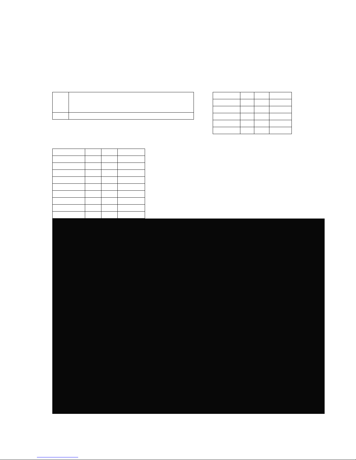
B SERVICE CONNECTIONS
Models: Capella – 4 & Capella – 6
Capella Service Connections: ELECTRICAL (Capella - 4) 60 Hz
Electrical Connection – 1 1/8” knock-out hole
EC
for electrical connection. Rating provided on
data label.
D Drain – A 6 ft. removable drain hose
ELECTRICAL (Capella - 6) 60 Hz
Voltage pH kW Amps
208 1 8 38.5
240 1 8 33.3
208 3 8 22.2
240 3 8 19.3
208 1 9.8 47
240 1 9.8 41
208 3 9.8 27
240 3 9.8 24
480 3 9 12
Voltage pH kW Amps
208 1 8 39
240 1 8 33
208 3 8 22
240 3 8 19
480 3 7.2 9
NOTES:
4” clearance left mandatory, right and rear is recommended.
Location near a floor drain is recommended.
Refer to the electrical charts (above and to the left) for proper
voltage requirements for each steamer.
7
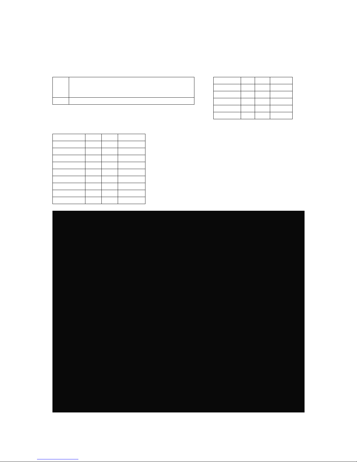
SERVICE CONNECTIONS (continued)
Models: Capella – 8, Capella – 10 & Capella – 12
Capella Service Connections: ELECTRICAL (Capella - 4) 60 Hz
Electrical Connection – 1 1/8” knock-out hole
EC
for electrical connection. Rating provided on
data label.
D Drain – A 6 ft. removable drain hose
ELECTRICAL (Capella - 6) 60 Hz
Voltage pH kW Amps
208 1 8 38.5
240 1 8 33.3
208 3 8 22.2
240 3 8 19.3
208 1 9.8 47
240 1 9.8 41
208 3 9.8 27
240 3 9.8 24
480 3 9 12
Voltage pH kW Amps
208 1 8 39
240 1 8 33
208 3 8 22
240 3 8 19
480 3 7.2 9
NOTES:
4” clearance left mandatory, right and rear is recommended.
Location near a floor drain is recommended.
Steamer sizes can be mix matched. Two 4-pan (Capella-4)
stacked together makes an 8-pan steamer (Capella-8), a 4pan and 6-pan (Capella-4 & -6) stacked together makes a 10pan steamer (Capella-10), and two 6-pans (Capella-6)
stacked together makes a 12-pan steamer (Capella-12).
Refer to the electrical charts (above and to the left) for proper
voltage requirements for each steamer.
Each compartment, stacked or single, requires a separate
electrical connection.
8
C INSTALLATION
1) Damage Inspection: Reporting shipping damage is the responsibility of the purchaser.
Do not discard packaging if filing a freight damage claim. Upon receipt of steamer
immediately inspect the exterior of packaging for damage. Remove wrapping. Inspect the
exterior of the Capella for visible shipping damage.
2) Unpacking / removal from pallet: To remove the steamer from the pallet, carefully cut
the strapping.
3) Legs / caster installation: Install 4 legs or casters (shipped inside the steamer) into the
threaded mounting holes located on the base of the unit. If casters are supplied, locking
casters should be on the front of the steamer.
4) Vent pipe installation (double & single compartment steamers): Steamers come with
the vent piping in rear of unit completely assembled. DO NOT BLOCK VENT PIPE.
5) Drain Hose: Shipped inside the steamer is the hose used for draining the steamer. DO
NOT DISCARD.
6) Physical location of steamer: 98% of all maintenance and service can be done from
the front or left side. Some local codes may require installation under ventilation, but
ventilation is not required in most cases. A minimum of 4” clearance from adjacent
equipment on the left side and rear is recommended.
NOTE: A location near water and a floor sink or drain is useful, but not necessary.
NOTE: A qualified electrician must perform all electrical hookups and meet all local codes.
Installation is the responsibility of the purchaser.
7) Electrical hookups: The access hole to electrically wire your steamer is located in the
bottom right corner (facing the back of the steamer) on the rear panel. Your electrician
may install a cord set to make the steamer more portable or the unit may be hard-wired.
Please follow local codes when installing the cord set.
NOTE: Stacked units will require 2 separate electrical connections.
8) Electrical Diagrams: The electrical diagrams are located on the inside of the left side
access panel.
9) Recommended water quality: This steamer does not require filtered water. However, it
is important to properly drain and clean your water reservoir at least daily (see 6.0
Cleaning Guidelines in this manual).
NOTE: Low water probe will not sense water level if steamer uses de-ionized water or reverse
osmosis water.
10) Ball valve drain: Drain is activated by a manual ball valve on the lower left front of the
steamer. Turn counterclockwise to open, clockwise to close. Drain hose, supplied with
steamer, must be connected to threaded drain before opening valve.
!
!
WARNING: The water may be very hot. It is advisable to allow the water to cool down
before draining. Leaving the door open will aid cooling.
11) Leveling: Once the legs have been installed and the steamer has been placed in its final
location, the unit must be leveled. This is done by turning the base of the leg. Use the top
of the steamer casing as a reference. It is recommended to use a level to ensure proper
installation.
WARNING: The steamer must be level in order for the low water sensor to function
properly.
12) Rack Installation: Two pan support racks have been included with the steamer. Both
racks are identical; there is no specific left or right side rack. To install, position a rack
inside the cooking chamber so that the mounting bracket, with the ‘tear-drop’ shaped
9

hole, fits over the pre-installed rack screws at the top of the cooking chamber wall. The
curved wires on the rack should be facing to the front of the steamer. Repeat this process
for the rack mounted on the other side. These racks are designed to be removed easily
for cleaning.
13) Function tests / inspection: Once your steamer is in place and properly leveled,
plumbed and wired, test unit to make sure it is functioning properly.
D STARTUP PROCEDURE
1) Using a soft sponge and mild detergent, wipe out the interior of the cooking chamber to
remove shipping debris prior to use. Rinse with clean water.
CAUTION: Do not use any abrasive cleaners, utensils or scrubbers on the non-stick coating. Use
vinegar and water to clean reservoir. Nylon bristle brushes or soft sponges are recommended.
2) Make sure drain valve is in the CLOSE position. Fill the cooking chamber with 2 ½
gallons of water – or to about 1” below the door opening. Make sure water is above the
level of the water probe on the lower left side of the cooking chamber.
3) Power on/heat up: Make sure the door is closed and turn the cooking mode selector to
the 1 position. The Amber HEAT light on the upper left corner of the control panel will
turn on. You may smell smoke from oils left from manufacturing – don’t be alarmed, they
will burn off quickly. When the HEAT light goes out you are ready to test the steamer.
4) Turn the cooking mode selector switch to the 2 position. The HEATING light will go on as
heat is called for. You may open the door and inspect the steaming process (note that the
HEAT light goes out and the heaters are turned off when the door is opened).
5) Connect the drain hose and put the open end in a bucket or near a floor drain. With the
door shut, open the drain and allow the water to drain below the water level probe. The
ADD WATER light should illuminate.
6) To shut down your steamer, turn the cooking mode selector to the OFF position ( ).
7) Open the steamer door to allow it to cool and complete draining the cooking chamber. If
draining into a bucket, remember that the cooking chamber can hold 2 ½ gallons of hot
water.
WARNING: The water hose or ball valve may be very hot. It is advisable to allow the water to
cool down before draining. Leaving the door open will aid in cooling.
E OPERATION
1) Electrical Connection: Make sure unit is plugged into a proper receptacle or wired
properly and the breaker for the circuit is on.
2) Add water: Make sure drain valve is in the CLOSE position. Pour 2 ½ gallons of water
into the cooking chamber through the door opening – or to about 1” below the door
opening. Make sure water is above the level of the water probe on the lower left side of
the cooking chamber. Water should not touch the bottom of the lowest pan. If the
steamer is hot from prior use DO NOT add water to a hot, dry cooking chamber. Allow
cooking chamber to cool with the door open first.
3) Reservoir fill / Add Water light: During the course of the day, as the water level
decreases, the ADD WATER light (green) on the control panel will come on. If this light is
on for more than one minute a safety sensor will shut down power to the heaters. The
light will remain on until water is added. When water is added the cooking chamber will
come back to the set temperature and resume cooking. If water is added and the ADD
WATER light remains on, the water level sensing probe must be cleaned. Lower the
water level until the probe is above water and clean probe with a sponge or cloth. Refill
the cooking chamber. The ADD WATER light should go out. If water is not added or the
probe is not cleaned within 15 minutes, the CLEAN PROBE light (red) will come on.
When water is added, both CLEAN PROBE and ADD WATER light should go out. If the
10
 Loading...