

Market Forge Industries 30P-STEL, 40P-STEL, 30P-STEM, 40P-STEM Maintenance Manual
UNIVERSE PLUS STEL & STEM SERIES
ELECTRIC TILTING SKILLETS
INSTALLATION - OPERATION - MAINTENANCE
OPEN LEG BASED MODELS
30P-STEL
40P-STEL
42 Allen Martin Drive, Essex Junction, Vermont 05452 USA
Telephone: (802) 658-6600 Fax: (802) 864-0183
www.marketforge.com PN 14-0382 Rev C (9/18)
CLOSED BASED MODELS
30P-STEM
40P-STEM
© 2018 - Market Forge

Your Service Agency’s Address:
Model
Serial number
Skillet installed by
Installation checked by

IMPORTANT
This is the safety alert
symbol. It is used to alert you
to potential personal injury hazards. Obey all safety messages
that follow this symbol to avoid
possible injury or death.
WARNING: Improper installation, operation, adjustment,
alteration, service or maintenance can cause property damage, injury or death. Read the
installation, operating and maintenance instructions thoroughly
before installing, operating or
servicing this equipment.
Adequate clearances must be
maintained for servicing and
proper operation.
TABLE OF CONTENTS
INSTALLATION
Service Connections ..................................................... 2
Introduction .............................................................. 3
Installation Information ................................................... 4
OPERATION
Operating Instructions .................................................... 6
Suggested Cooking Temperatures ......................................... 7
MAINTENANCE
Cleaning & Troubleshooting ............................................... 9
Do not attempt to operate this
unit in the event of a power failure.
Intended for commercial use
only. Not for household use.
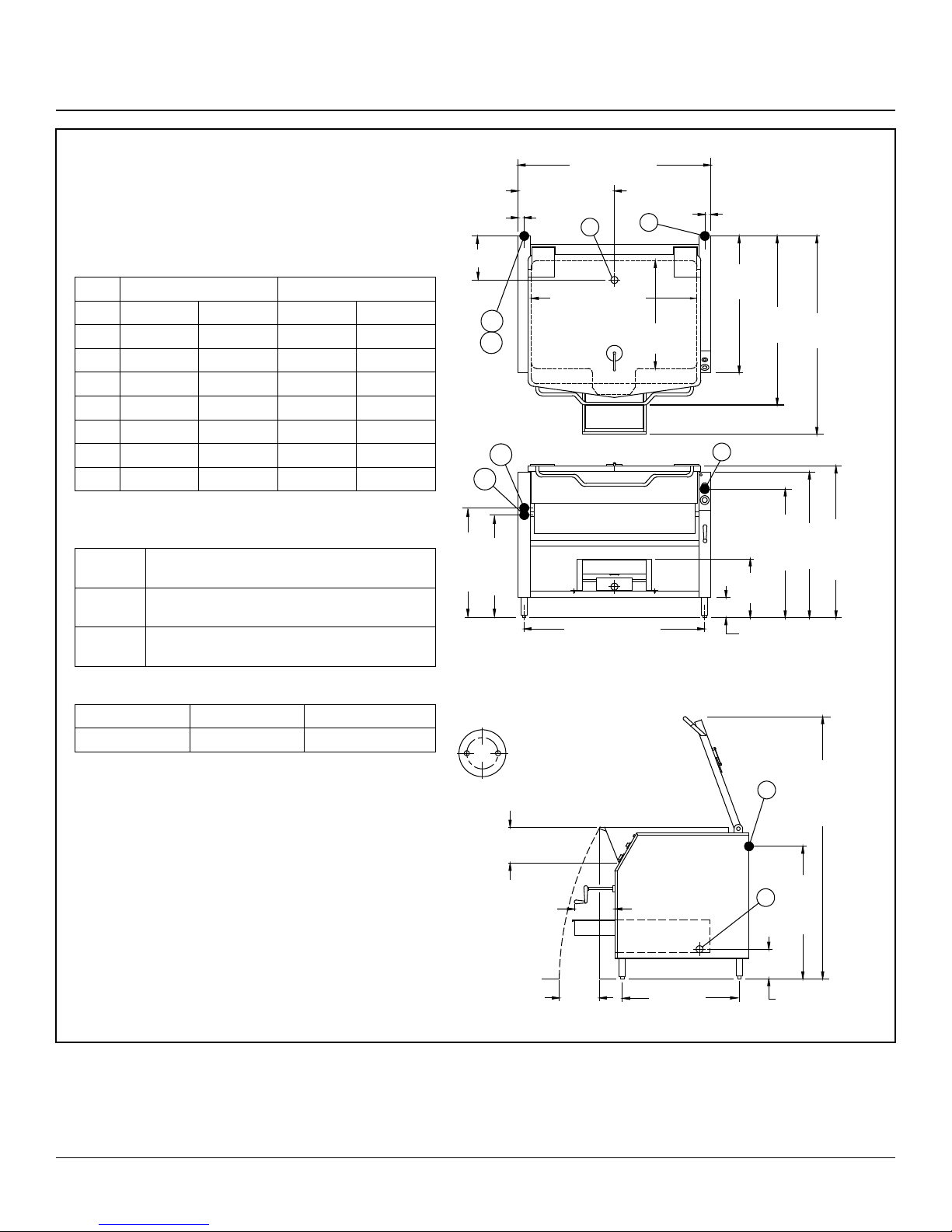
Service Connections
10 [254] CLEARANCE FROM WALL
OPERATION SHALL BE BY
All Universe Plus tilting skillets models are available in 208VAC,
240VAC, field convertible to 1 or 3 phase, or 480VAC 3 phase.
30 gallon models are rated at 12 kW and the 40 gallon models
are rated at 18 kW.
ELECTRICAL CHARACTERISTICS
40 gallon (18 kW) 30 gallon (12 kW)
VAC 1 pH 3 pH 1 pH 3 pH
208 57.7 33.3 86.5 50.0
220 54.5 31.5 81.8 47.2
240 50.0 28.9 75.0 43.3
380 n/a 18.2 n/a 27.3
415 n/a 16.7 n/a 25.0
480 n/a 14.4 n/a 21.7
600 n/a 11.5 n/a 17.3
Details of other electrical systems are available upon request.
SERVICE CONNECTIONS
E Electrical Connection - to be as specified on
data plate
CW / HW Cold & Hot Water - 3/8” O.D. NPT to faucet
(Optional)
D Drain - 1-1/2” drain NPT (Optional drain pan
assy)
INSTALLATION CLEARANCE
Left Side Right Side Rear
0 0 10” [254mm]
36 [914] 30 GAL.
46 [1168] 40 GAL.
18 [457] 30 GAL.
1.68 [43]
10.5 [267]
HW
CW
HW
29.6.9 [754]
Shown with optional drain pan assembly
23 [584] 40 GAL.
D
27.88 [708] 30 GAL.
37.88 [962] 40 GAL.
CW
27.94 [710]
32.63 [829] 30 GAL.
42.63 [1083] 40 GAL.
REAR FLANGE FOOT DETAIL
2 EQUALLY SPACED Ø 7/16 [11]
HOLDES ON 2.5 [63] B.C.
E
25.75
[654]
DIMENSIONS ARE
1.68 [43]
33
[838]
E
16.38
[416]
6 [152]
IN INCHES [MM]
41.44
48.88
[1052]
[1241]
36 [914]
31.63 [803]
E
37.75 [959]
INSTALLATION
9.5 [241]
PAN I.D.
Figure 1
2
12 [305]
POUR
PATH
12 [305]
29.75 [756]
73.34 [1863]
D
33.62 [854]
8.5
[216]
1.53 [39]
 Loading...