

Page 1
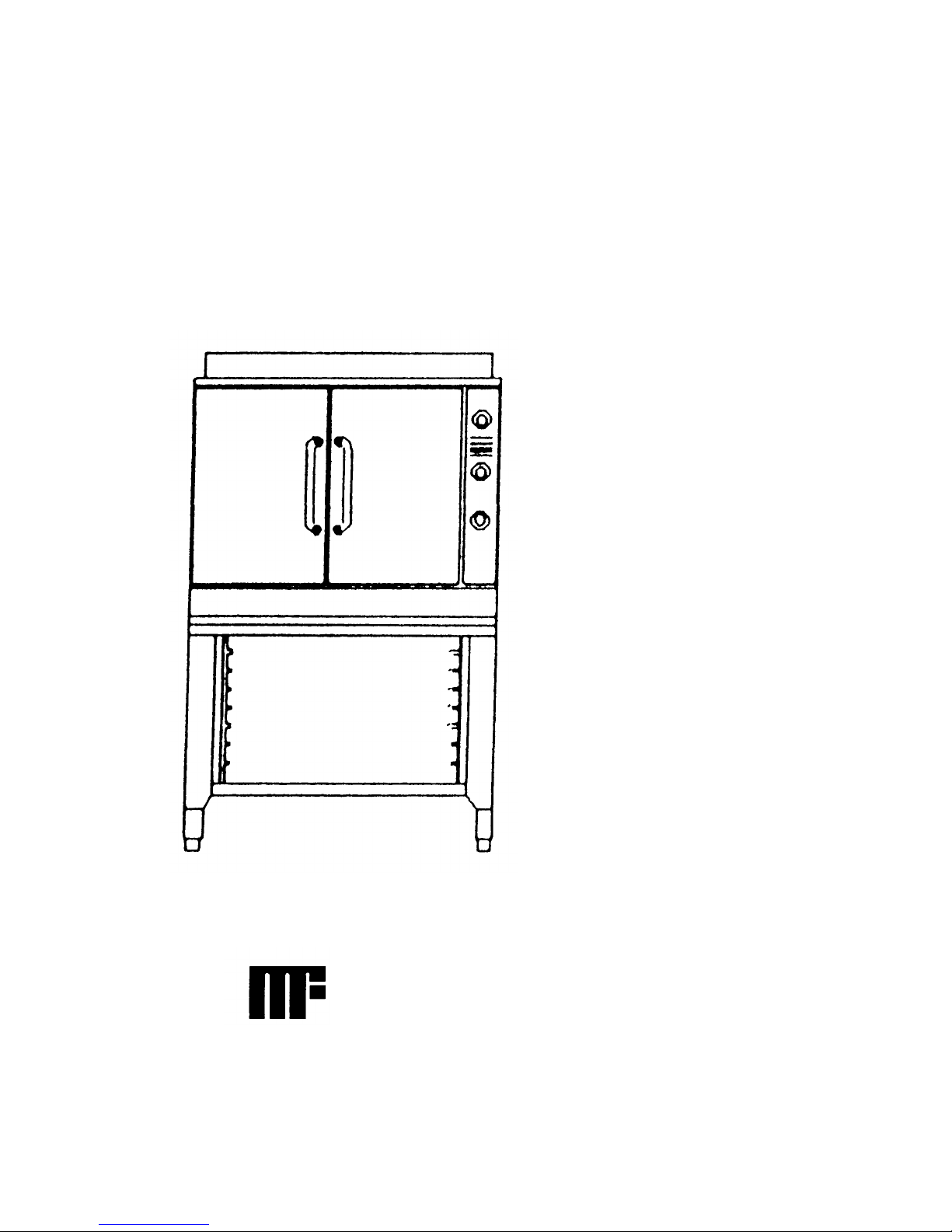
SERVICE & PARTS MANUAL
Models:
2500 HE
2700 HE
2592 HE
High Efficiency Gas Convection Oven
2792 HE
MARKET FORGE industries Inc
Employee Owned Company
World Headquarters: 35 Garvey Street, Everett, MA 02149
Tel. (617) 387-4100, Fax 800-227-2659 (U.S. Except MA) or (617) 387-4456 (In MA)
Form No. S-2207 6/94 Printed in U.S.A.
Page 2

TABLE OF CONTENTS
Paragraph Page Paragraph Page
SECTION 1 INTRODUCTION
11 Description 1-1 51 General 5-1
12 Basic Functioning 1-1 52 Trouble-Shooting Guide 5-1
13 Service 1-1 53 Electrical Fault Isolation 5-3
SECTION 2 INSTALLATION
21 Receiving 2-1 541 Incoming Power 5-3
22 Assembly 2-1 542 Electrical Inspection 5-3
221 Oven on 7" (178mm} Stand 2-1 543 Direct Spark Ignition System 5-3
222 Oven on Modular Base 2-1 544 Thermostatic Control 5-5
223 Oven on 28" (711mm} Open Stand 2-1 545 Solenoid Gas Valve 5-5
224 Stack Oven on 7" (178mm} Stand 2-1 546 Wiring 5-5
23 Gas Connection 2-3 547 Buzzer Relay 5-5
231 Placement 2-3
232 Materials 2-3 SECTION 6 MAINTENANCE
233 Connection 2-3 61 General 6-1
234 Gas Leak Test 2-3 62 Preventive Maintenance 6-1
24 Electrical Connection 2-3 63 Adjustment Procedures 6-1
25 Ventilation 2-5 631 Oven Door Adjustments 6-1
251 Flue Deflector Installation 2-5 632 Thermostat Calibration 6-2
26 Installation Check-Out 2-5 64 Repair and Replacement 6-2
261 Initial Control Settings 2-5 641 Control Panel Removal 6-2
262 Oven Check-Out 2-5 642 Right Side Panel Removal 6-3
263 Shut -Down Procedure 2-6 643 Fan Blade Removal 6-3
SECTION 3 OPERATION
31 Operating Controls and Indicators 3-1 646 Gas Valve Removal 6-4
32 Operating Procedures 3-1 647 Thermostat Removal 6-4
321 Preheating 3-1 648 Ignition Control Board Removal 6-4
322 Cooking 3-1 65 Adjustments and Operational
SECTION 4 PRINCIPLES OF OPERATION
41 General 4-1 652 Regulator Adjustment 6-4
42 Combustion/Vent Circuits 4-1
43 Electrical Circuits 4-2 SECTION 7 ILLUSTRATED PARTS LISTS
431 Control Circuit Components 4-2 71 General 7-1
SECTION 5 TROUBLE -SHOOTING
54 Electrical Trouble-Shooting
Procedures 5-3
644 Burner Pan Removal 6-3
645 Electrode Removal 6-4
Checks of Burner Components 6-4
651 Gas Burners 6-4
72 Ordering Information 7-1
73 Index of Illustrated Parts Lists 7-1
Page 3

LIST OF ILLUSTRATIONS
Figure
Page
SECTION 1 INTRODUCTION
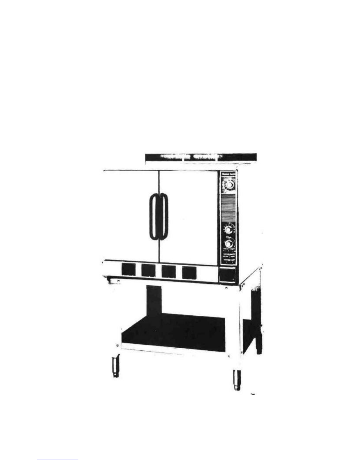
1-1 High Efficiency Gas Convection Oven
SECTION 2 INSTALLATION
2-1 7" Stand 2-1
2-2 28" Stand 2-2
2-3 Stacked Ovens 2-2
2-4 Service Connections 2-4
SECTION 3 OPERATION
3-1 Control Panel 3-2
SECTION 4 PRINCIPLES OF OPERATION
4-1 Cutaway Oven 4-1
4-2 Schematic Control Circuits 4-2
1-2
LIST OF TABLES
Figure
SECTION 5 TROUBLE -SHOOTING
5-1 Wiring Diagram 5-3
5-2 Flame Current Meter Placement 5-4
SECTION 6 MAINTENANCE
6 1 Blower Guard 6-1
6-2 Wheel Puller Kit 6-3
6-3 Air Shutter Adjustment 6-5
SECTION 7 ILLUSTRATED PARTS LISTS
7-1 Frame & Cabinet Assembly 7-2
7-2 Manifold & Burner Pan Assembly 7-4
7-3 Door Assembly 7-6
7-4 Control Panel Assembly 7-8
7-5 Ignition Control Board Assembly 7-10
Page
Table Page Table
SECTION 3 OPERATION SECTION 5 TROUBLE-SHOOTING
3-1 Control Panel Components 3-3 5-1 General Trouble-Shooting Guide 5-1
5-2 Electrical Fault Isolation Guide 5-2
Page
Page 4

SECTION 1 INTRODUCTION
This service and parts manual contains general information, installation, operation, principles of operation, trouble-
shooting, and maintenance information for the Market Forge High Efficiency Gas Convection Oven Also included
are parts lists, in which each replaceable part is identified and shown in an accompanying exploded view
1.1 DESCRIPTION
The Market Forge Model HE Gas Convection
Oven is a gas fired, pilotless, direct-spark-igni-tion
system convection oven The unit is designed to
operate from a natural, propane, or butane gas
supply when equipped with appropriate gas orifices
It consists of a heavily insulated cooking
compartment fitted with a convector fan and heated
by a gas burner system designed to achieve optimal
efficiency from the fuel burned All oven controls are
located on a recessed panel on the right front of the
oven as seen from the front
The major assemblies of the HE oven are the
stainless steel or baked enamel finish cabinet
enclosure, solid doors, stainless steel cooking
compartment with nine shelf supports, convector
fan, pressure regulator and gas valve manifold
assembly, burner box assembly consisting of gas
burners, orifices, and direct spark ignition elec trode
The control panel assembly includes the thermostat,
electronic ignition control board, 60-minute and 5hour mechanical timers, red indicator light, ON-OFF
power switch, warning buzzer, and ignition and
motor reset switches
The unit is available in a variety of mounting
configurations 7" (178mm) counter stand, 28"
(711mm) modular base, open stand on legs with
shelf and optional storage rack, or stacked on top of
another HE oven with the bottom unit on 6" (152mm)
stainless steel legs
1.2 BASIC FUNCTIONING
The HE oven becomes operational when the
power switch is placed in the ON position, doors are
closed, and thermostat set Electronic ignition
activates, energizing the burner electrodes and
opening the gas valve (The fan operates continuously
with power on and doors closed, regardless of
thermostat setting ) Gas passes through the regulator
and valve to the burners, where it is ignited by the
sparking of the elec trodes The resulting flame heats a
flame baffle plate mounted under the cooking
chamber, which in turn heats the chamber The fan
circulates air uniformly through the chamber When the
chamber reaches the preset temperature, the
thermostat contacts open and the gas valve closes
When the temperature drops enough to close the
contacts, the ignition system reactivates Any number
of such cycles might occur during the cooking time If
for any reason the burners fail to ignite, the system
automatically closes the gas valve Should the burners
go out prematurely, the system will automatically activate the ignition electrodes, and if flame is not
established the system will shut down and close the
gas valve
1.3 SERVICE
Required service, both preventive and corrective,
is explained in Section 6 Should repairs be required, a
network of authorized agencies is
Page 5
available to assist with prompt service. A current directory
of Authorized Service Agencies may be obtained by
contacting:
Product Service Department
Market Forge
35 Garvey Street
Everett, Massachusetts 02149
Telephone (617) 387-4100
Product Service Department
Market Forge Canada Ltd.
1375 Aimco Blvd., Unit 5
Mississauga, Ontario, Canada L4W 1B5
Telephone (416) 621-9252
The model and serial numbers must be referenced when
corresponding with Market Forge. The data plate with serial
number is located on the center of the bottom front trim
ledge.
Figure 1-1. High Efficiency Gas Convection Oven on Optional Stand
Page 6
SECTION 2 INSTALLATION
2.1 RECEIVING
The oven is shipped bolted to a skid and cov ered by
a carton which is nailed to the skid, these must be
carefully removed prior to installation DO NOT AT ANY
TIME LAY THE OVEN ON ITS TOP, SIDE, OR FRONT
TO DO SO MAY DAMAGE THE EQUIPMENT AND
INVALIDATE THE WARRANTY
2.2 ASSEMBLY
Set-up and assembly procedures for the various oven
configurations are described in the following paragraphs
2.2.1 Oven on 7" (178mm) Stand
1. Screw legs (Figure 2-1, #4) into top frame assembly
(1)
2. Place into position front and rearchannel assembly
(2) and side angles (3) These items are loose parts
and are tied together with mounting of oven to stand
3. For single oven, mount oven to stand using four
3/8-16 x 3/4 Ig hex head cap screws and four 3/8
plain washers provided
4. For stacked oven, proceed to paragraph 2 2 4
5. For single oven, proceed to subsection 2 3
2.2.2 Oven on Modular Base
1. Screw adjustable feet into cabinet base
2. Mount oven to base using four 3/8- 16 x 3/4 Ig
hex head cap screws and four % plain washers
provided
3. Proceed to subsection 2 3
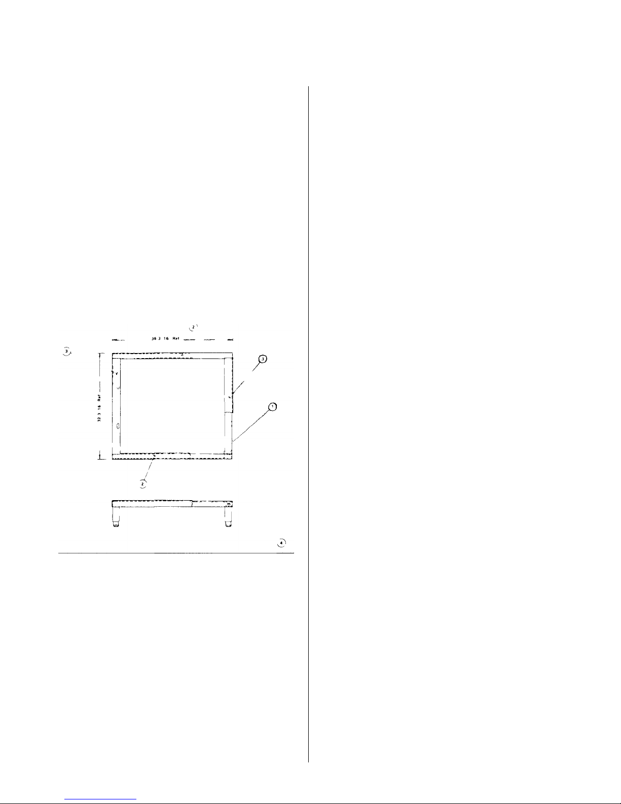
2.2.3 Oven on 28" (711mm) Open Stand
1. Place top frame (Figure 2-2, #2) upside down on
a clean smooth surface
2. Place into position front and rear angle as semblies (8) (stainless only) and legs (1)
3. Align holes in legs, frame, and angle assemblies
Secure using carriage bolts, lockwash-ers, and
nuts provided (5,6,7)
4. Align holes in shelf (3) with leg holes and secure
using hardware (5,6,7)
5. Screw adjustable feet (4) into stand legs
6. Install four clips for oven rack support inside top
frame using hardware (5,6,7) optional
7. Place stand in upright position Install rack
support, if supplied, inserting ends through holes
in clips and shelf
8. Mount oven to stand using four ¾-16 x 3/4 Ig
hex head cap screws and four 3/8 plain washers
provided
9. Proceed to subsection 2. 3
Figure 2-1. 7" (178mm) Stand
2.2.4 Stack ovens on 7" (178mm) stand
See 2.2.1 for stand assembly and proceed as
Follows:
1. Remove rear panels from both ovens by
removing 14 Phillips head screws from each
rear panel.
Page 7
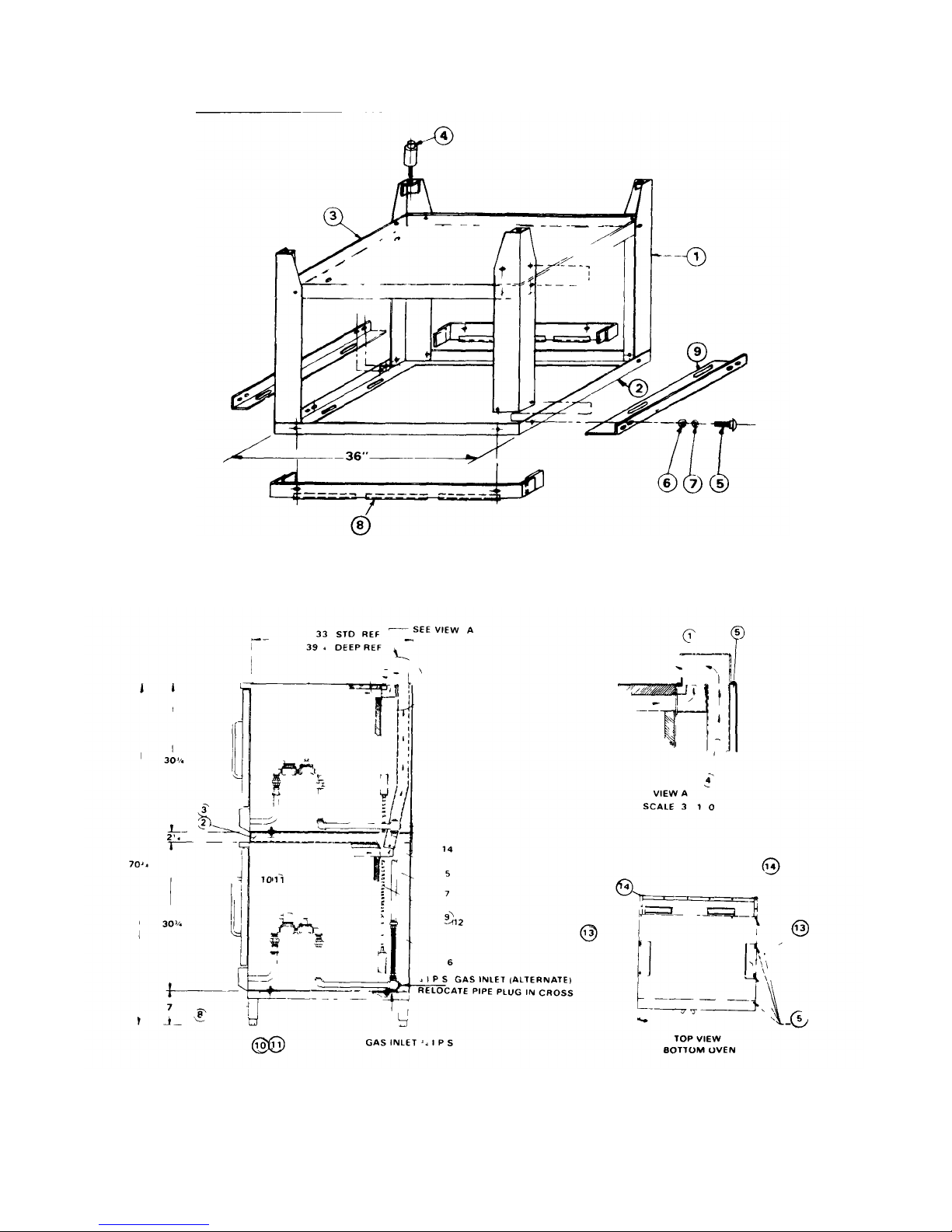
Figure 2-2 28" (711mmi Open Stand (Inverted for Assembly)
Figure 2-3 Stacked Ovens
Page 8

2. Tilt ovens onto left sides as seen from front to
access bottoms DO NOT AT ANY TIME LAY THE
OVENS DOWN ON TOPS, RIGHT SIDES, OR
FRONTS. TO DO SO MAY DAMAGE THE
EQUIPMENT AND INVALIDATE THE WARRANTY
3. Install 7" (178mm} stand to bottom oven using
hardware (Figure 2-3, #10, 11). Either oven may
serve as bottom oven. Stand is 32" (813} front to
back. When used with deep ovens, overhang may
be either front or back, as desired. (Recommended
overhang is in back )
4. Stand bottom oven upright, onto stand.
5. Install top retaining brackets (13) on top of bottom
oven by removing two screws from top panel, left
and right, as shown, and replacing through holes in
brackets.
6. Install spacer assembly (2 or 3) on bottom of top
oven using hardware (10, 11).
7. Stack top oven on bottom oven.
8. Attach long flue assemblies (4) to top and bottom
ovens. See Figure 2-3, view "A".
NOTE
If stacked ovens are adjacent to moisture producing
equipment (such as kettles or steam cookers) it is
necessary to seal the seam between the stacked ovens
and the moisture producing equipment to prevent
condensation from entering the control section of the
bottom oven Silicone synthetic rubber is recommended
for a sealant
rear wall if adjoining wall is combustible Allow 6" (152mm}
clearance on right from another gas fired heat generating
piece of equipment, unless the equipment is another Market
Forge High Efficiency Oven, in which case no spacinq is
needed.
2.3.2 Materials
Use new pipe 3/4" (19mm} IP S properly reamed, free from
chips, and threaded to the proper length. If pipe dope is
used, apply a moderate amount, leaving two end threads
bare If Teflon tape is used, apply one and one-half turns,
leave ing the two end threads bare
2.3.3 Connection
Connect the gas line into the oven bottom at the right rear as
seen from the front, or alternate connection right rear back.
See Figure 2-4 For stacked ovens, connect gas pipe lines
between ovens using 3/4" (19mm} I.P.S. flexible connector
(Figure 2-3, #6) and 3/4" (19mm} I.P.S. x 20 1/4 tg nipple
(7). Install 3/4" (19mm} external gas supply shut -off valve
(furnished with unit) in an easily accessible location.
NOTE:
MANIFOLD PRESSURE MUST BE 4.0" (102mm} WATER
COLUMN FOR NATURAL GAS OVENS AND 10.0"
(254mm} FOR LP GAS OVENS SUPPLY PRESSURE
MUST BE AT LEAST 6.0" (152mm} FOR NATURAL GAS
AND 100" (254mm} FOR LP GAS. INSTALL PIPE PLUG IN
SIDE OF PIPE NOT BEING USED TO FEED GAS TO UNIT
2.3 GAS CONNECTION
This oven is factory adjusted for a gas consumption
rate of 60,000 BTU/hour. Read the nameplate on the
lower front access panel If this plate is marked for a
different gas than that being supplied, notify your dealer
immediately. DO NOT CONNECT GAS LINES Only a
qualified service technician should make the installation.
Installation must conform with the National Fuel Gas
Code ANSI Z223 1-1974, or CSAB1491 installation
codes, where applicable.
2.3.1 Placement
Allow 2" (51mm} clearance from side wall and
2.3.4 Gas Leak Test
Perform a gas leak test of all newly made joints, as well as
those leading to the main gas control valve. Check for leaks
using soap solution. DO NOT USE FLAME.
2.4 ELECTRICAL CONNECTION
Where applicable, installation must conform with
National Electrical Code ANSI C1-1975 or Canadian
Electrical Code C22 1, and/or local codes.
Page 9
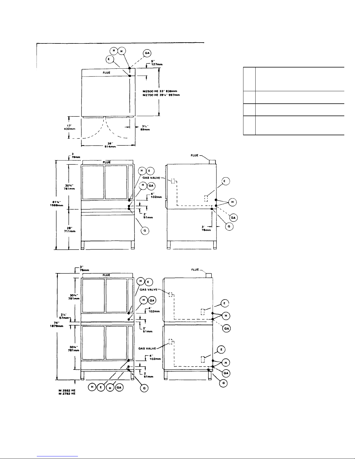
SERVICE CONNECTIONS
Hz.
1/2" 13mm conduit connection or equivalent
amps per oven Use wire suitable for at
Alternate
2.
Access to electrical junction box
GAS OPERATED
E
Electrical connection — 120 volt AC. 60
10
least 90°C
G 3/4" 19mm I.P.S Gas Connection Inlet,
Standard
GA 3/4" 19mm I.P.S Gas Connection Inlet,
H 1 3/4" 44mm dia. access holes for
1. Alternate gas supply connection GA
Page 10

1. Connect the power supply wires to the junction
box at the right back of the oven Use wire
suitable for at least 90°C Ensure that hot wire
connects to terminal L1 and neutral wire to L2
2. For stacked ovens, connect power supply to
bottom oven junction box Install flexible conduit
assembly (Figure 2-3, #9 or 12) between top
and bottom junction boxes
3. Ground unit using ground lug in supply box
4. Replace rear panel(s)
5. For stacked ovens, add back retainer clips
(Figure 2-3, #14) to back of both units using
existing screws
2.5 VENTILATION
Proper ventilation is highly important for good
oven operation The use of a mechanical exhaust
system is ideal A properly designed unit will extend
approximately 4" to 6" (102-152mm) beyond all
sides of the oven unit In such instances the oven will
be equipped with a flue deflector, which is shipped
separate from the oven in the stand carton If the flue
outlet is to be connected directly to a chimney, then
a down draft diverter should be employed AT NO
TIME SHOULD A DAMPER BE INSTALLED IN THE
EXHAUST SYSTEM OF THIS OVEN
2.5.1 Flue Deflector Installation
To install deflector, remove back row of screws from
oven top panel Add flue deflector with open side
facing front, and replace screws For stacked ovens,
see Figure 2-3, view "A"
2.6 INSTALLATION CHECK-OUT
After the oven is completely assembled and
properly located with gas and electrical supplies
connected, the unit should be given a thorough
check-out before being put into operation Check-out
procedures for the oven are given in subsection 2 6
2 If the unit fails to perform as described, consult the
trouble shooting guides in section 5 for corrective
action
Before making this check-out, the operator must
be thoroughly familiar with the operating procedures
in Section 3, and with the function of
each control described in Table 3 1 Reference Figure
3-1 for identification of controls
2.6.1 Initial Control Settings
Power switch and thermostat dial are in OFF
position
2.6.2 Oven Check-Out
A final check of the controls and connections
should be made as follows
1. Make sure that the blower guard is properly
mounted See Figure 6-1
2. With a level on the oven shelves make sure that
the oven is level both front and back left and right
To adjust, turn feet in stand legs NOTE Be sure
wire shelf supports are in, not on, brackets
3. Make sure that gas and electrical supplies are
available to the unit
4. Set thermostat dial at 350°F
5. Place power switch in the ON position with doors
open
6. Close doors Indicator light should come on, fan
should come on and rotate clockwise (seen from
front) NOTE Buzzer may sound for an instant
a) If fan does not start, or starts and immediately
stops, press MOTOR RESET
b) If buzzer sounds, press IGNITION RESET
7. If fan still does not work or buzzer sounds again,
see Tables 5-1 and 5-2 for troubleshooting and
electrical fault isolation
8. Indicator light will remain on while oven is heating,
and go out when preset temperature is reached
During the heat -up period, some slight smoke or
fumes may result due to oil or grease on metal
surfaces This should cease after five minutes
9. During initial burner operation, observe flame
angle of each burner through the louvers on the
lower front panel If flames are not vertical, burners
may not be positioned properly, see subsection
6.4.4
10. After this check is completed, turn thermostat dial
and power switch to OFF position
Page 11

2.6.3 Shut-Down Procedure
1. For daily shut -down, place thermostat dial
and power switch in OFF position.
2. For extended shut-down, place thermostat dial and
power switch in OFF position. Close external gas
supply shut -off valve. Leave doors ajar.
Page 12

SECTION 3 OPERATION
3.1 OPERATING CONTROLS AND
INDICATORS
All the controls required to operate the oven are
listed in Table 3-1 with a short functional description
of each. Figure 3-1 shows the physical location of
each control and indicator.
3.2 OPERATING PROCEDURES
Before attempting to use the oven for cook ing,
be sure that proper gas and electrical connections
have been made, gas supply valve is open, and fan
guard properly mounted.
3.2.1 Preheating
1. Arrange shelf positions according to the item to
be cooked. Refer to Test Kitchen Bulletin #41
for correct positioning.
2. Place power switch in the ON position. Close
doors. Fan should come on and rotate clockwise. If not, depress the MOTOR RESET but ton. If fan still does not operate, consult Table 5-
1.
3. Set thermostat dial to desired temperature.
Indicator light should come on. Burners should
ignite. If not, buzzer will sound. Depress the
IGNITION RESET button. If burners still do not
ignite, consult Table 5-1.
4. Preheat to temperature and allow to cycle once
(indicator light on, off, on) to obtain
even temperature throughout oven Total time:
approximately 15 minutes
3.2.2 Cooking
The oven is ready for cooking use when the
indicator light goes off. The load should be adjacent to
the oven, so that doors will be open as short a time as
possible during loading.
1. Load oven. If using oven for long term roasting of
meats, fish, or poultry, place about a quart of
water in the oven in a suitable container or under
a trivet in the same pan as the food.
2. Close doors and set timer for desired cooking
time.
NOTE: Timer is for convenience only and does not
control oven operation. Bell will ring at end of
preset interval.
3. Unload oven and proceed as follows:
a) If oven is to be turned off, place thermostat
dial and power switch in the OFF position.
b) If oven temperature is to be lowered, set
thermostat to desired temperature. Close right
door and leave left door open. Fan will
continue to run. When light comes on, oven is
at lower temperature. Close left door. When
light goes off, oven is ready to use.
4. Place thermostat dial and power switch in OFF
position for daily shut -down. For extended shutdown, place dial and switch in OFF position,
close gas supply valve, and leave doors ajar.
3-1
Page 13

HIGH EFFICIENCY CONVECTION OVEN
3-2
Page 14

TABLE 3-1
FIGURE 3-1 REF. DESCRIPTION FUNCTION
1 Thermostat Dial
2 60-Minute Timer
Regulates oven temperature by controlling burner operation. When
set, activates gas valve and ignition system.
Mechanical timer to aid operator in timing cooking cycle. Does not
control oven operation.
3 5-Hour Timer Same as 60-Minute Timer
4 Power Switch
5 Indicator Light
Controls power to control circuits and convector fan. Must be in ON
position for oven to operate
Indicates when lit that burners are operating Cycles on and off with
thermostat control.
Resets direct spark ignition system. If burners do not ignite after 3.3
6 Ignition Reset
seconds of ignition sparking, system locks out, closing gas valve.
Buzzer will sound. Press to reset system.
7 Motor Reset Circuit breaker protecting fan motor and control circuits. Press to reset.
3-3
Page 15

SECTION 4 PRINCIPLES OF OPERATION
4.1 GENERAL
The HE gas fired convection oven employs a carefully
designed ventilation combustion system which achieves
optimal control of combustion products. A convector fan
distributes heat uniformly throughout the oven interior The
gas burners are ignited by a pilotless, direct spark ignition
system. Cooking temperature is maintained by a thermostat
mounted on the control panel. Manual 60-minute and 5 hour
timers assist the operator but do not control oven operation
4.2 COMBUSTION/VENT CIRCUITS
With electrical power applied, gas supply
valve open, and the power switch on, electrical control
circuits are activated to energize the burner electrodes
Gas passes through the regulator and valve to the burner
orifices. Primary air enters the burner tubes through
shutter openings and mixes with the gas, which is ignited
by the ignition electrodes. The flame heats a baffle plate
mounted under the cooking chamber. Heat passes to the
oven interior by radiant and convection transfer from the
baffle plate. Combustion products are directed via internal
flues around the sides of the cooking chamber, where
additional heating is achieved, and into the flue deflector
at the top.
Figure 4-1 Cutaway Oven
4-1
Page 16

4.3 ELECTRICAL CIRCUITS
120 volt a-c power is supplied to the fan motor,
indicator light, and ignition control board, which in turn
controls power to the burner electrodes. IGNITION RESET
switch, and gas valve solenoid Input power is connected at
the junction box mounted (behind an access cover) at the
lower right rear of the oven.
4.3.1 Control Circuit Components
The control circuit is shown in the simplified schematic
drawing Figure 4-2. A brief description of major electrical
control circuit components is included in the following
paragraphs.
4.3.1.1 Door Interlock Switch
The interlock switch is a single pole, two-position
micro-switch with normally open contacts. The switch lever
is operated by an actuating
Figure 4-2 Simplified Schematic — Controls in OFF position
bar built into the door jamb of the right side door When the
door is open, the bar remains retracted with the switch
contacts in the normally open position. When the door is
closed, the door pushes the actuating bar against the switch
lever to close the contacts. Connected into the circuit for the
fan and ignition system, the door switch interrupts fan
operation and deactivates the ignition system when the door
is opened
4.3.1.2 Thermostat Control
The thermostat is a bulb and capillary type system,
manually adjustable from 200-475°F (94-246°C).The oven is
put into an automatic heating cycle with the setting of the
thermostat to any of its calibrated temperature settings.
Expansion and contraction of gas with in the capillary/bellows system in response to temperature change
opens and closes the thermostat contacts, energizing and
de-energizing the ignition control system
4.3.1.3 Direct Spark Ignition System
The direct spark ignition system consists of the
electrodes, ignition control board, and associated wiring. On
a call for heat, input power is applied to the control board.
Sparking is then initiated and the gas valve is energized.
Sparking continues with the gas valve powered for a "trial
for ignition" period of 3.3 seconds. If flame has not been
established by the end of the trial period, the system will
lock out, the gas valve will close, the reset function will trip
out, and a warning buzzer will sound. Reset action is manually accomplished by pressing IGNITION RESET switch In
normal operation, as soon as flame is established and
proven by the flame sensing circuitry, sparking will cease
immediately and the system will remain "on", monitoring the
flame until the end of the duty cycle. Should flame -out occur
during the duty cycle, the system will reactivate the spark to
provide for reignition.
The flame will either be reestablished or the system will
lock out in the normal manner. Should lock-out occur, the
system is reactivated by the IGNITION RESET switch
located on the control panel.
4-2
Page 17

SECTION 5 TROUBLE-SHOOTING
PROBLEM
a) Power to oven is off.
Locate external circuit breaker for power and place
a) External gas supply shut
-
off Open valve
5.1 GENERAL
The information in this section is intended to
assist both the operator and service personnel in
described in Section 3. If the problem cannot be
readily corrected, the operator should contact the
nearest Market Forge Service Agency for assistance
locating the general source of problems which may
occur with the High Efficiency Convection Oven.
Before following any of the procedures given in this
section, the operator should be thoroughly familiar
with the operating instruc tions and the function of all
5.2 TROUBLE-SHOOTING GUIDE
A general trouble-shooting guide for use by
service personnel is given in Table 5-1
controls which are
TABLE 5-1 GENERAL TROUBLE-SHOOTING
GUIDE
Probable Cause Remedy
1. CONVECTOR FAN FAILS TO OPERATE.
in ON position
b) Control circuit breaker open. Press MOTOR RESET
c) Right oven door open. Close door
d) ON-OFF switch off Place in ON position
e) Faulty circuit breaker, power Test each component and connecting wiring. Re
switch, door switch, fan motor, or place as required
wiring.
2. GAS BURNERS FAIL TO IGNITE (BUZZER SOUNDS)
closed.
b) Ignition circuit locked out Press IGNITION RESET
c) Gas solenoid valve fails in closed Replace valve.
position.
d) Faulty control board. Replace control board. See subsection 6.4.8.
e) Faulty electrode unit Replace electrode unit See subsection 6. 4.5.
f) Damaged or loose wire. Trace all wiring from control board to controls.
ly connected and located at least 1/2" (13mm} from
5- 1 S 2207
Check to see that all wiring is secured, and that the
high and low voltage leads to electrode are proper-
ground.
Page 18

TABLE 5-1 (cont )
3. INDICATOR LIGHT FAILS TO LIGHT WITH THERMOSTAT SET, FAN OPERATING
a) Indicator light burned out Replace light
b) Thermostat contacts faulty Replace thermostat
c) faulty wiring Check wiring from door switch to thermostat and light
4. ERRATIC OVEN TEMPERATURE
a) faulty thermostat operation
5.3 ELECTRICAL FAULT ISOLATION
Correction of an electrical failure first requires
isolation of the fault to a single circuit or component. In
most cases the nature of the failure and its effect upon
Recalibrate or replace as required See subsection 6.3.2
(neutral lead to wire #11) Make sure the unit is
properly grounded to the ground lug in the Junc tion
box If 120 vo lts are present, the fault lies in the
electrical circuits of the oven
the operation of the oven will be sufficient to isolate it
to one or more circuit elements Table 5-2 is provided
as a guide for isolating electrical faults.
5.4 ELECTRICAL TROUBLE-SHOOTING
PROCEDURES
Before performing the trouble-shooting pro-
cedures in this section the serviceman must be
familiar with the function of all controls as described in
Section 3 and with the Principles of Operation
described in Section 4.
Electrical trouble-shooting procedures which
follow require access to components and terminals of
the operating controls and ignition control board
Electrical controls are reached by removing the control
panel as described in paragraph 6.4.1 Wiring and
terminal locations are shown in Figure 5-1. Figure 4-2
shows the circuit schematically
5.4.2 Electrical Inspection
The first step in any electrical trouble-shooting
procedure is a thorough inspection of all wiring
connections To access the electrical components,
remove control panel as described in subsection 6.4.1
WARNING
Before removing the control panel or checking
connections or wiring, make sure incoming
power is shut off When power is supplied, all
exposed terminals carry 120 volts
Check all connections by hand to ensure that all
connection points are tightly secured Use a
screwdriver to tighten if necessary Inspect all quickdisconnect terminals for evidence of corrosion
Terminals in this condition should be replaced
5.4.1 Incoming Power
Before trouble-shooting any of the electrical parts
or assemblies, make sure power is being supplied to
the junction box (Figure 7-1, #11). With power
connected to the oven, an a-c voltmeter is used to
measure 120 volts across terminals to lines coded L1
(hot lead to wi re #1) and L2
5.4.3 Direct Spark Ignition System
The ignition control board and associated
components are the main electrical control for
operation of the HE oven If it is determined that the
electrical controls (solenoid valve, RESET switches,
electrode, etc ,) are not damaged and
5-2
Page 19

TROUBLESHOOTING
1.
Will not operate when thermostat is set.
a. Incoming power
Figure
5-1.
Wiring Diagram
the interconnecting wiring is complete and not
TABLE 5-2
ELECTRICAL FAULT ISOLATION GUIDE
FAILURE FAULT LOCATION
2. Intermittent operation of burners
b. Door switch
c. Faulty thermostat
d. Wiring
e. Ignition system control board
f. Ignition electrode
g. Gas valve solenoid
a. Damaged control system. Refer to paragraph
3. Indicator light off (system operating) a. Indicator light
4. System fails to operate upon pressing RESET a. RESET switch
switch
5. Convector fan fails to operate a. Circuit breaker
b. Thermostat malfunction
b. Wiring
b. Wiring
b. On-Off switch
c. Door switch
d. Fan motor
damaged, the trouble is due to a malfunction of the
components on the ignition control board.
Components on the control board are not replaceable
and a damaged control board must be replaced as a
functional unit. The following paragraphs outline
possible problems and symptoms that may be
encountered during the normal use of the oven.
CAUTION
IF A CONTROL BOARD IS REPLACED, BE SURE
THAT THE HIGH VOLTAGE LEAD OF THE
ELECTRODE IS CONNECTED TO TERMINAL E1
AND THE LOW VOLTAGE LEAD IS CONNECTED
TO TERMINAL E2 OF THE CONTROL BOARD.
5-3
Page 20

5.4.3.1 Improper Polarity
If a spark is present and the gas valve opens but the system
shuts down after the trial period, check the 120 volt a c input
voltage at terminals A (L1) ,and L2 of the control board for
proper polarity Terminal A should be the hot side and L2
neutral with respect to ground.
5.4.3.2 Damaged Grounding
If a spark is present and gas valve opens but the
system shuts down after the trial period, check to make sure
the system is properly grounded to the burner and the
burner itself is properly grounded Proper grounding is
essential for the proof of flame safety device. If the system
is not grounded to the burner, it cannot determine the
presence of flame and will lock out A restart will initiate the
trial for ignition period, but the system will continue to go into
'lock out' if it is not properly grounded, and the thermal reset
will trip. Wait one minute before pushing the IGNITION
RESET button. Check all power and ground terminals to
make sure good contact is made. Clean any corrosion that
might interfere with good electrical contact.
5.4.3.3 Malfunction Due To High Voltage
During the trial for ignition, if the spark is intermittent
and the valve may (or may not) open, check the spark gap
on the electrodes and system wiring as follows:
1. Remove the electrode from the burner and check to see
that the gap is 1/8" ± 1/32". If not, replace electrode.
2. Check the ceramic housing and lead wires for cracks or
breaks.
3. Check terminals E1 and E2 for inadvertent grounding.
They should be at least 1/2" from metal objects which
can cause arcing to ground. If the electrode or lead
wires are faulty replace with new components.
5.4.3.4 Malfunction Of Gas Valve
If the board is receiving proper power and sparking
occurs during the trial for ignition period but the valve does
not open, check the valve for an open coil or other
malfunction. Be sure
Figure 52 Placement of Flume Current Meter
voltage rating of the valve is 120 volts a-c. Use a voltage
tester or voltmeter at terminals B and V2 of the ignition control
board. Voltage should be 120V
5.4.3.5 Erratic Operation
If the system operates properly for a while but randomly
shuts down during the duty cycle, or won't operate during
'cold' starts, check the flame proving circuit with a d-c
microamp meter Refer to Figure 5-2 and proceed as follows:
1. Locate ignition control board (Figure 7-5, 2) 2 Remove low
voltage wire from terminal E2 and connect one lead of
microamp meter to push-on connector attached to lead
wire.
3. Connect second lead of meter to terminal E2 on ignition
control board.
4. Energize control board and read current on microamp
meter. Typical flame current is 2 to 20 microamperes.
If low or marginal flame current is present, it is tripping the
thermal reset switch. If this is the case, relocate the electrodes
or flame sensor into the flame to increase the flame current. If
the ignitor is switched off and on several times in succession,
the thermal reset switch will trip, and it will have to be reset. If
ignition is not achieved after the first two or three attempts,
check to ensure that the other components in the system are
functioning correctly.
Page 21

5.4.4 Thermostatic Control
5.4.4.1 Thermostat Contacts
Defective contacts will result in failure of the
oven to operate properly. If the ignition system fails
to operate when the thermostat knob is set to the
desired temperature, the fault may be the
thermostat switch contacts or thermostat wiring.
When this occurs, remove the control panel
(subsection 6.4.1) and proceed as follows.
1. Turn off power to the oven at external (main)
circuit breaker
2. Disconnect all wires (8,9,18) from thermostat
terminals (See Figure 5-1)
3. Connect an ohmmeter between the terminals
4. Rotate the thermostat knob to the maximum
setting With the oven cool, a zero ohm reading
should be obtained on the ohmmeter. If zero
reading cannot be obtained, contacts are
defective and the thermostat must be replaced.
5. Remove ohmmeter and replace all leads on
terminals as shown in Figure 5-1
5.4.4.2 Thermostat Capillary
A defective or punctured capillary/bellows
system may cause continuous operation of the
burners. If continuous operation occurs and
recalibration of the thermostat as explained in
subsection 6.3.2 fails to correct the problem, the
entire thermostat control must be replaced
If voltage of 120 volts is present, the valve is defective
and must be replaced as a unit If 120 volts is not
present and all wiring connections are tight, the
ignition control board is defective and must be
replaced
5.4.6 Wiring
All the electrical components of the HE oven (ON-
OFF switch, door switch, thermostat control, gas
solenoid valve, RESET switches, ignition control
board, and indicator light) are connected to each other
by wiring shown in Figure 5-1. If all of the electrical
components are operating correctly (and the incoming
power has been checked) but the unit fails to operate,
the fault lies in the wiring.
Figure 5-1 is a wiring diagram which shows all
terminals and interconnections within the electrical
circuits All numbered terminals are identified and all
leads number coded as shown Connections can be
easily removed Figure 4-2 shows the same
information schematically and is an aid in isolating
circuits for testing
Using an ohmmeter, wiring continuity between the
connections shown on the wiring diagram (Figure 5-1)
is readily verified. This is best done in stages,
removing only those wires required for eac h continuity
check. As each lead is replaced, it should be checked
for evidence of corrosion and cleaned if necessary. All
leads must be tightly attached to provide a good elec trical connection.
5.4.5 Solenoid Gas Valve
When the solenoid gas valve fails to operate,
the fault may be a defective valve or control board.
An a-c voltmeter is used to check the voltage at the
coil wire terminals with the oven operating.
5.4.7 Buzzer Relay
A defective relay will cause continuous sounding
of the buzzer when the thermostat is set If the buzzer
is sounding but the burners are operating properly, the
relay is defective and must be replaced.
5-5 S2207
Page 22

SECTION 6 MAINTENANCE
6.1 GENERAL
This section contains both preventive and
corrective maintenance information. Preventive
maintenance may be performed by maintenance
personnel at the establishment in which the oven is
installed. It is recommended that user personnel
never attempt to make repairs without the assistance
of an authorized service agency. Assistance in
service methods or a current directory of authorized
Service Agencies may be obtained from Market Forge
(See subsection 1.3).
6.2 PREVENTIVE MAINTENANCE
A good preventive maintenance program in the
form of daily cleaning procedures is outlined in the
following steps
1. Remove oven shelves and wash in mild detergent
and water. Rinse and dry.
2. Remove left and right hand shelf supports by
lifting up and out toward center of oven Wash,
rinse, and dry.
3. Remove fan guard (Figure 6 1) by lifting up and
out Wash, rinse, and dry.
4. Wash interior sides, bottom, and top with mild
detergent and water. A stainless steel cleaner
(not polish) should be used for the interior Rinse
and dry.
5. Replace fan guard, shelf supports, and shelves.
6. Wash both sides of doors, using a stainless steel
cleaner Rinse and dry.
6.3 ADJUSTMENT PROCEDURES
6.3.1 Oven Door Adjustments
Access to adjustable parts is obtained by first
removing upper door trim strips.
Figure 6 1 Blower Guard
6.3.1.1 Door Catch Adjustment
Remove upper and lower trim strips and proceed
as follows
1. Loosen door catch assembly mounting screws (Fig
7-3, #4) at top and bottom of door frame.
2. Move door catch assembly (7) in or out as required
to hold door firmly against oven front. Do not
leave any gaps or space between roller on door
catch assembly and dimple on door trim.
3. Tighten the screws (4) and replace trim.
6- 1 S 2207
Page 23

6.3.1.2 Door Switch Adjustment
1. Remove upper oven trim strip by removing four
screws (Fig 7-3, #1 & 2) left and right
2. Loosen the two hex nuts on the end of the
switch retaining screws Move the switch to the
left or the right as required, and retighten the
hex nuts Use care when retightening to avoid
damaging the switch
3. Open and close door several times to check
switch adjustment Repeat step 2 as required to
obtain proper operation
4. Replace trim and panel
6.3.1.3 Oven Door Horizontal Adjustment
To adjust the doors horizontally (either left to
right or front to back)
1. Remove top front trim (Figure 7-3) by remov ing
screws (1 & 2, left and right)
2. Loosen four hex nuts (15, two at top and two [not
shown] at bottom) on both doors
3. Reposition both doors using the following as a
guide
4. Close both doors
5. Set doors square with top angle and control
panel The gap between the doors (actually the
raised embossment on the edges) should be
approximately 1/32" (1mm} It is import ant that
this gap be maintained the full height of the
doors
6. Open left door Check that inside surface of door
trim hits against raised edge of oven liner at
point 'A', top and bottom Tighten four hex nuts
(15)
7. Repeat the same (#6) for right door Recheck for
squareness and 1 /32" (1mm} gap Readjust if
necessary
8. Replace trim
6.3.1.4 Oven Door Vertical Adjustment
To adjust the doors vertically
1. Loosen the two hex nuts (Figure 7-3, 9)
2. Back off top door pivot pin (8)
3. Reposition door by turning bottom door pivot pin
(8) Turn pin clockwise (up) or counter-clockwise
(down) as required Top of doors should be level
with each other and equally
spaced between top and bottom trim.
4. Retighten the two hex nuts
HIGH EFFICIENCY CONVECTION OVEN
6.3.2 Thermostat Calibration
If the oven components are operating but the unit
is not cooking properly, the thermostat may need
calibration To calibrate, proceed as fol lows
1. Attach a thermocouple lead to the bulb of the
thermostat and close oven doors
2. Place power switch in the ON position
3. Set thermostat dial at 400°F and carefully remove
the switch control knob
4. Allow the unit to heat until the indicator light has
gone out twice
5. Note the temperature reading on the thermocouple
a) If the temperature reading is off 50° or more,
the thermostat must be replaced
b) If the reading is off less than 50°F, adjust the
thermostat setting using a fine blade screwdriver
in the stem of the thermostat
6. With the oven temperature set at 400°F, the
cycling should retain a peak of 420°F and a low of
380°F after two stabilizing cycles A good
indication of proper calibration is the temperature
at which the burners ignite and shut off It should
be:
Cut off 400-405°F
Cut in 380-385°F
7. After completing calibration, apply Duco cement
or equivalent to the adjusting screw of the
thermostat and replace the knob
6.4 REPAIR AND REPLACEMENT
Section 7 of this manual contains a listing of all
replaceable parts and associated exploded views of
the model HE gas convection oven In most cases
disassembly procedures are obvious from the
exploded views. Disassembly and as sembly
instructions follow for procedures which are not
readily apparent
6.4.1 Control Panel Removal
1. Remove four screws from control panel (Figure 7-
4). All controls on the panel are serviceable from
the front.
6-2 S2207
Page 24

MAINTENANCE
2. Remove panel carefully to avoid damaging connections
WARNING
Controls carry 120 volts Be sure that ex ternal circuit
breaker is shut off before removing panel to avoid
accidental shock or short circuit
6.4.2 Right Side Panel Removal
1. Remove four screws from rear of right side panel
3. Remove six screws from control panel
4. Remove right side panel to gain access to gas valve
and regulator Gas valve and regulator may also be
accessed by removing control panel only
WARNING
Controls carry 120 volts Be sure that external circuit
breaker is shut off before removing panel to avoid
accidental shock or short circuit
6.4.3 Fan Disassembly and Repair
6.4.3.1 Fan Blade Removal
Removal of the fan requires use of a wheel puller kit
(part #99-3334) supplied by Market Forge Wheel puller kit
components are shown in Figure 6-2 To remove fan blade,
proceed as follows
1. Remove fan guard (Fig 7-1,18)
2. Remove Allen head set screws which secure fan to
motor shaft
3. Install wheel puller over hub of fan using Allen head
cap screws
4. Gradually tighten hex bolt on wheel puller until fan
slides off motor shaft
5. Remove wheel puller from fan blade and reinstall
replacement fan on motor shaft as required
6.4.3.2 Fan Motor Removal
Motor removal is completed from inside the oven.
With external circuit breaker shut off, proceed as follows
1. Remove fan guard (Fig 7-1, 18).
Figure 6 2 Wheel Puller Kit Components
2. Remove four nuts (17) and clips (16) from motor
assembly
3. Pull motor forward, carefully disconnect electrical wiring,
and slide motor off screws
4. Install replacement motor assembly as re quired
6.4.4 Burner Pan Removal
1. Remove control panel (See subsection 6.4.1 )
2. Break union below gas valve (Figure 7-2, 35)
3. Remove bottom front louvered panel
4. Disconnect the high voltage lead and the low voltage
lead from their connections at the ignition electrode (25)
and slide the wires out from their respective guides
along the front of the burner pan
5. Remove the two screws (16) that retain man ifold shield
assembly (17) Remove assembly by tipping it forward
and down
6. Remove end seals (10) from burner pan assembly by
removing screws (18) and prying channels out.
7. Remove manifold retaining bolt (11) and washer(7).
8. Remove screws from front of burner pan assembly (6).
Slide assembly out.
6.4.4.1 Burner Removal
1. Remove burner pan (See subsection 6.4.4).
2. Pop off retaining clip and slide burner tube (Fig 7-2, 4)
out from manifold.
6-3 S 2207
Page 25

6.4.4.2 Flame Baffle Assembly Removal
1. Remove burner pan assembly (see subsec tion 6.
4.4) to access flame baffle assembly (Fig 7-2 26.)
2. Remove two screws (32) from flame baffle front
support clips (31) left and right. Remove clips and
allow flame baffle to tip down into burner cavity.
3. Slide baffle forward and off rear support
channel.
6.4.5 Electrode Removal
1. Remove bottom front louvered panel (Fig 7-3
#34).
2. Disconnect high voltage lead and low voltage lead
by removing retaining nuts, washers, and
terminals.
3. Remove two retaining screws (Fig 7-2, #12) from
electrode mounting plate Slide out electrode (25).
6.4.6 Gas Valve Removal
1. Remove right side panel (see subsection 6.4.2).
2. Break two unions (Fig 7-2, #35) connecting gas
valve and regulator to manifold. Remove valve
and regulator assembly.
3. Unscrew gas valve from close nipple (34) and
elbow (33).
6.4.7 Thermostat Removal
1. Remove six screws from top panel (Fig 7-1,5) on
right side of ove n.
2. Remove four screws from rear panel (7).
3. Remove four screws from control panel (13).
4. Remove right side panel (9).
5. Remove five screws that secure perforated
capillary tube guard to oven liner.
6. Slide thermostat bulb out from clips and through
hole in side of oven.
7. Slide entire assembly out front of oven through the
control area.
8. Install replacement thermostat as required.
6.4.8 Ignition Control Board Removal
To access ignition control board, remove control
panel See subsection 6.4.1.
HIGH EFFICIENCY CONVECTION ION OVEN
1. Disconnect high and low voltage electrodes and
wires to reset switch, gas valve, and terminal strip
2. Remove screws, nuts, lockwashers, and spacers
from board. Remove control board.
6.5 ADJUSTMENTS AND OPERATIONAL CHECKS
OF BURNER COMPONENTS
During normal use or when parts are replaced,
certain adjustments must be made to gas burners,
pressure regulator, and electrode assembly.
Procedures are outlined in the following paragraphs.
6.5.1 Gas Burners
The burners and fixed orifices are sized at the
factory for natural gas operation. The burner air
shutters should be adjusted at the proper opening to
produce a blue flame without yellow tipping. To adjust
air shutters, see Fig 6-3 Refer to Fig 6-3 indexes for
correct orifices to be used with cert ain gases.
6.5.2 Regulator Adjustment
Regulator (Fig 7 2, 2) is factory set at 4" (102mm}
and adjustable from 3 5 6" water column gas pressure
for natural gas, factory set at 10" {254mm) and
adjustable from 6115" for propane or butane gas.
Check input by attaching manometer to downstream
pressure tapping of manifold (behind front louver, right
side) by removing plug fitting with burners off. To
adjust, proceed as follows.
1. Remove right side panel (see subsection 6.4.2).
2. With the main burner operating, remove pressure
regulator cover screw.
3. Turn the valve adjusting screw (located under the
cover) clockwise to increase, or counter clockwise
to decrease the gas flow. Do not exceed the input
rating on the unit nameplate.
4. To ensure proper adjustment , cycle main burners
on and off several times by means of the
thermostat switch.
6-4 S 2207
Page 26

MAINTENANCE
Figure 6-3. Air Shutter Adjustment
6-5
Page 27

SECTION 7 ILLUSTRATED PARTS LISTS
7-2 Gas Burner and Manifold Assembly
7-5 7-3
Door Assembly
7-7 7-4
Control Panel Assembly
7-8
7.1 GENERAL
This section contains a complete listing of all
replaceable parts of the High Efficiency gas convection oven. For the purposes of part identification,
the unit is broken down into functional assemblies,
and each assembly is shown in an exploded view
which is keyed to the accompany ing parts list. Each
parts list contains the figure index number, the
Market Forge part number, and an abbreviated
description.
7.3 INDEX OF ILLUSTRATED PARTS LISTS
Figure
7-1 Cabinet and Frame Assembly 7-3
7.2 ORDERING INFORMATION
Orders for repair parts should be directed to the
nearest authorized parts distributor. For a current Market
Forge Authorized Parts Distributor List contact:
Customer Service Department
Market Forge
35 Garvey Street
Everett, Massachusetts 02149
Telephone: (617) 387-4100
Customer Service Department
Market Forge Canada, Ltd.
1375 Aimco Blvd., Unit 5
Mississauga, Ontario, Canada L4W 1B5
Telephone: (416) 621-9252
Page
7-5 Ignition Control Board Assembly 7-10
7-1 S-2207
Page 28

Figure 7-1. Frame and Cabinet Assembly
Page 29

ILLUSTRATED PARTS LIST 7-3
INDEX NO.
PART NO.
DESCRIPTION
1 99-3932
Motor Ass'y
- 60
Hz 115/230V
INSULATION
*19 10-8212
Bottom Rear Insulation (Maronite)
*Denotes Items Not Shown
FIG. 7-1
2 99-1925 Clip
3 10-1295 Rack Support - Standard
3a 10-1296 Rack Support - Deep
4 99-1579 L/H Panel Ass'y - Standard - Enamel
4a 99-1578 L/H Panel Ass'y - Deep - Enamel
5 99-4431 Top Panel - Standard - Enamel
5a 99-4429 Top Panel - Deep - Enamel
5b 99-4435 Top Panel - Standard - Stainless Steel
5c 99-4434 Top Panel - Deep - Stainless Steel
6 99-4137 Flue Deflector - Enamel
6a 99-4138 Flue Deflector - Stainless Steel
7 99-1572 Rear Panel - Enamel
7a 99-3386 Rear Panel - Stainless Steel
8 10-6870 Transformer (Export only) 100V
9 99-1576 R/H Panel Ass'y - Standard - Enamel
10 99-4507 Connector Box (Export only)
11 10-5291 Terminal Box
12 99-4368 Base Ass'y
13 99-4819 Control Panel Plate
14 10-6415 Control Panel Bezel
15 10-5453 Blower Wheel
16 99-0951 Clip
17 10-2335 Hex Nut 5/16-18
18 10-5957 Fan Guard
*20 09-5413 Rear Insulation
*21 10-8219 Lt. Side Insulation (Model 2500)
*22 10-8220 Rt. Side Insulation (Model 2500)
*23 09-5415 Lt. Side Insulation, Top (Model 2500)
*24 09-5418 Rt. Side Insulation, Top (Model 2500)
*25 10-8216 Lt. Side Insulation, Top (Model 2700)
*26 10-8218 Rt. Side Insulation (Model 2700)
*27 09-5414 Lt. Side Insulation, Top (Model 2700)
*28 09-5417 Rt. Side Insulation, Top (Model 2700)
S-2207
Page 30

HIGH EFFICIENCY CONVECTION OVEN
Figure 7-2. Gas Burner and Manifold Assembly
7-4
Page 31

ILLUSTRATED PARTS LIST 7-5
FIG.
7-2 PART NO.
DESCRIPTION
1 10-7694
Gas Valve
- Magnetic Solenoid
2 09-1150 Pressure Regulator - Natural
2a 09-1151 Pressure Regulator - Propane
3 99-4424 Cross & Bracket Ass'y
4 10-3258 Gas Burner
5 99-3968 Manifold Ass'y
6 99-4349 Burner Pan Ass'y (Standard)
6a 99-4366 Burner Pan Ass'y (Deep)
7 10-2400 Washer 1/4" Plain
8 10-2330 Hex Nut 8-32
9 10-2518 Lockwasher #8
10 99-4355 End Seal—Manifold Shield Ass'y
11 10-1804 Hex Hd. Screw 1/4" - 20 x 5/8" Ig.
12 10-1722 Screw Mach. Rd. Hd. #6-32 x 3/8" Ig.
13 10-2347 Speednut
14 10-1956 Phill. Truss Hd. Scr. Type "A" #8-32
15 99-4358 Support Clip—Electrode Wires
16 10-1954 Phill. Rd. Hd. Mach. Scr. #8-32 x 1 5/8"
17 99-4351 Manifold Shield Ass'y
18 10-1735 Phill. Rd. Hd. Sheet Scr. 3/8" Ig.
19 10-1735 Phill. Rd. Hd. Sheet Scr. 3/8" Ig.
20 99-4356 Bottom Seal—Manifold Shield Ass'y
21 10-1855 Pan Hd. Scr. Type "F" 8-32 x 3/8" Ig.
22 10-3366 Burner Orifice #49 (.078) Natural Gas
23 10-3367 Burner Orifice #56 (.465) Propane
24 10-8226 Burner Orifice #57 (.043) Butane
25 10-8090 Ignition Electrode
26 99-3925 Flame Baffle Ass'y (Standard)
26a 99-3927 Flame Baffle Ass'y (Deep)
27 10-1954 Pan Hd. Mach. Scr. #8-32 x 3/8"
28 10-2330 Washer #8
29 10-2408 Hex Nut #8-32
30 99-3564 Support Bracket
31 99-4362 Front Support Clips - Flame Baffle
32 10-1761 Truss Hd. Mach. Scr. #8 - 32 x 3/8"
33 10-2811 Street Elbow 90° M.I. 1/2
34 10-2810 Close Nipple B.I. 1/2
35 10-3332 Union M.I. 1/2
36 10-2876 Reducing Coupling M.I. 3/4-1/2
37 99-4359 Retaining Clip—Electrode Wires
38 99-4585 Gas Burner With Electrode Bracket
39 10-8136 High Voltage Wire
S-2207
Page 32

HIGH EFFICIENCY CONVECTION OVEN
Figure
7-3.
Door Assembly
7-6
Page 33

ILLUSTRATED PARTS LIST 7- 7
FIG. 7-3
PART NO.
DESCRIPTION
1 10-1717
Rd Hd Mach Scr
#8 - 32 x
3/8
2 10-1956 Phil Truss Hd Type 'A' #8 x 3/8
3 10-2341 Washer - Thin #10
4 10-1759 Rd Hd Mach Scr #10 - 32 x 3/8 Ig.
5 10-2509 Lock Washer #10
6 10-2432 Washer - Med #10
7 99-3362 Assembly - Spring Door Catch - (single roller)
7a 99-4785 Assembly - Spring Door Catch - (double roller)
8 99-3279 Pivot Pin - Door
9 10-2552 Hex Nut - 3/8" - 24
10 99-3557 Support Brk't
11 10-1761 #8 - 32 Truss Hd Mach Scr x 3/8 Ig.
12 10-2330 Hex Nut #8 - 32
13 10-2518 Lock Washer #8
14 99-3559 Bushing
15 10-2340 Hex Nut #10-32
16 10-2509 Lock Washer #10
17 99-3562 Trip Lever Ass'y
18 10-2432 Washer - Med #10
19 99-1251 Insulation Shield
20 10-6859 Door Micro-Switch (Not Shown)
21 99-3511 Door Pivot Pin Support
22 10-2523 Ext Tooth L Washer 1/4 x 3/4 O.D. x .035
23 10-1997 Flat Head Machine Screw
24 10-1997 Flat Head Machine Screw
25 10-2337 Hex Nut
26 10-1895 Lock Washer
27 10-1996 #8 - 32 Ft Hd Mach Scr #6 - 32 x 1/2" Ig.
28 99-3237 Head Shield Ass'y Rt Frt
29 99-3283 Front Frame Ass'y
30 99-3378 Hinge Ass'y - Locking Truck
31 10-1990 Button Socket Hd Scr w/Lok #10-24 x 1 - 3/4 Ig.
32 99-3534 Door Assembly - Stainless Steel
33 10-0657 Door Handle
34 99-4399 Louver
35 10-2432 Washer
36 10-1760 Screw
37 99-4361 Spacer
38 99-4396 Louver
S-2207
Page 34

HIGH EFFICIENCY CONVECTION OVEN
7-8
Figure 7-4 Control Panel Assembly
Page 35

ILLUSTRATED PARTS LIST 7-9
4
FIG. 7-
INDEX NO.
PART NO. DESCRIPTION
1 99-4209 Control Panel Assembly—Complete
(excluding thermostat)
2 10-6307 Knob
2a 09-5270 Knob, For (60) Mm. Timer
2b 09-5259 Knob, For (5) Hour Timer
3 99-5301 Nameplate—Bottom Section
3a 08-5916 Overlay For (2) Speed Switch
(must be ordered together with 99-5301)
4 10-6415 Bezel
5 10-4714 Thermostat
6 10-5520 60 Minute Timer
7 10-5553 5 Hour Timer
8 10-5016 Indicator Light
9 10-6264 On - Off Switch
10 09-8015 Reset Switch (supplied with Circuit Breaker Board)
11 10-6266 Motor Reset Switch—12 Amp
S-2207
Page 36

7-10
HIGH EFFICIENCY CONVECTION OVEN
Figure
7-5.
Ignition Control Board Assembly
Page 37

ITEM NO.
1 95-4465
Bracket for Control Board
&
Buzzer
ILLUSTRATED PARTS LIST
7-11
FIG. 7-5
PART NO. DESCRIPTION
2 10-8258 Ignition Control Board
3 10-6512 Socket
3a 10-9175 Socket*
4a 10-9174 Mini-relay*
5 10-6682 Buzzer 120V
6 10-1717 Screw, Rd. Hd. Mach. #8 - 32 x 3/8" Ig.
7 10-2420 Washer, Plain #6
8 10-2330 Hex Nut #8 - 32
9 10-1747 Screw, Rd. Hd. Mach. #8 - 32 x 5/8" Ig.
10 10-1849 Screw, Rd. Hd. Mach. #6 - 32 x 1/2" Ig.
11 10-2420 Washer, Plain #6
12 10-2337 Hex Nut #6 - 32
* Must be purchased together.
S-2207
 Loading...