

Page 1

TS-E TURBO STEAM
ELECTRIC COUNTERTOP CONVECTION STEAMER
PARTS AND SERVICE MANUAL
EFFECTIVE JUNE 12, 2017
The Company reserves the right to make substitution in the event that items specied are not available.
ERRORS: Descriptive and/or typographic errors are subject to correction.
Superseding All Previous Parts Lists.
MARKET FORGE
Telephone: (802) 658-6600 Fax: (802) 860-3732
www.marketforge.com
P/N 14-0291 Rev C (6/17)
Page 2

TABLE OF CONTENTS
TROUBLESHOOTING ..................................................................3
ELEMENT BLOCK REPLACEMENT .....................................................5
WIRING DIAGRAMS ...................................................................6
ILLUSTRATED PART LIST
TS-E EXPLODED VIEW ................................................................9
FLOOR DRAIN KIT ASSEMBLY ....................................................... 12
JUNE 12, 2017 2 TS-E ELECTRIC COUNTERTOP STEAMERS
Page 3
TROUBLESHOOTING
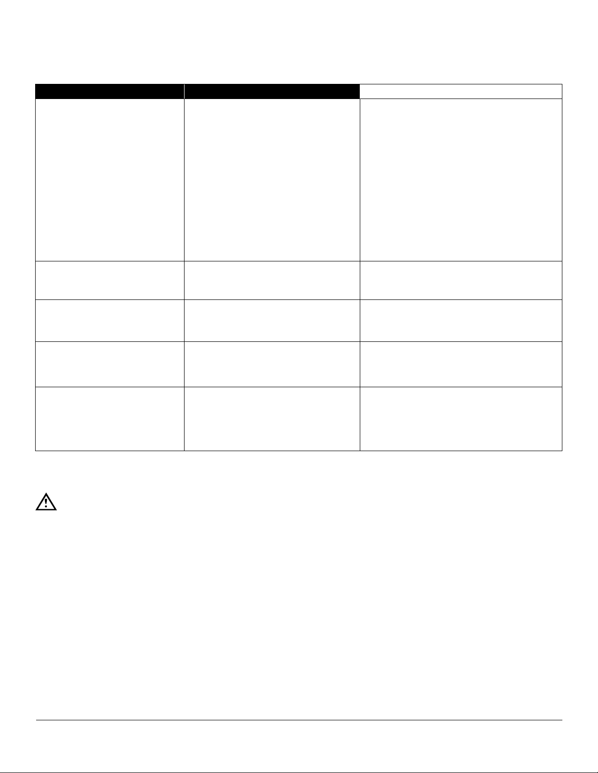
GENERAL TROUBLE-SHOOTING GUIDE
PROBLEM PROBABLE CAUSE REMEDY
COOKING INDICATOR LIGHT
FAILS TO LIGHT WITH TIMER
SET.
STEAM FAILS TO GENERATE
WITH COOKING INDICATOR
LIGHT ON.
STEAMS CONTINUOUSLY
WITHOUT THE COOKING OR
READY LIGHT ON.
TIMER DIAL NOT TURNING. a. Faulty timer motor.
a. Main power circuit breaker tripped.
b. Door interlock switch contacts not
closed.
c. Door interlock switch faulty.
d. Indicator light burned out.
e. Faulty timer contacts.
f. Faulty wiring.
g. Fuse blown.
a. Faulty wiring. a. Inspect condition of wire and tightness of
a. Faulty thermostatic switch. a. Replace thermostat.
a. Locate external circuit breaker for incom-
ing power and place in ON position.
b. Shut cooker door to close switch contacts.
Check alignment of door with switch.
c. Replace switch.
d. Replace light.
e. Replace timer.
f. Inspect condition of wire and tightness of
all connections. Correct as needed.
g. Replace with same rated fuse.
all connections. Correct as needed.
a. Replace timer.
b. Faulty wiring.
BUZZER FAILS TO SOUND AT
END OF TIMER SETTING.
COMPONENT TESTING
Exterior Panel Removal
WARNING
To prevent hazard in servicing the cooker, be
certain that the electrical disconnect circuit
breaker for the steamer is OFF before removing side panels.
Access to all internal plumbing and electrical assemblies
is from the right side. The right-side panel is removed by
removing the bottom screws from panel.
60-MINUTE TIMER
Timer Contacts
Defective timer contacts will result in failure of cooker
compartment to operate. When this occurs, remove the
side panel and proceed as follows:
1. Turn off power at external circuit breaker.
a. Timer contacts faulty.
b. Buzzer faulty.
c. Faulty wiring.
b. Inspect condition of wire and tightness of
all connections. Correct as needed.
a. Replace timer.
b. Replace buzzer.
c. Inspect condition of wire and tightness of
all connections. Correct as needed.
3. Connect an ohmmeter between terminals 21 and 22.
4. Rotate timer dial beyond the “0 - Minute” point (any
setting) to obtain a reading of zero ohms on the ohmmeter. If zero ohm reading cannot be obtained, timer
contacts are defective and the timer must be replaced.
5. Move ohmmeter leads to terminals 21 and 24.
6. Rotate timer dial to “0 - Minute” position. (An audible
click indicates correct position). If zero ohm reading
cannot be obtained, the timer is defective and must
be replaced.
7. Move ohmmeter leads to terminals 11 and 12.
8. Rotate the timer dial to the “CONSTANT STEAM” position. If zero ohm reading cannot be obtained, the
timer is defective and must be replaced.
9. Remove ohmmeter and replace all three leads on
timer terminals.
2. Disconnect all three wires from timer terminals.
JUNE 12, 2017 3 TS-E ELECTRIC COUNTERTOP STEAMERS
Page 4

TROUBLESHOOTING
Timer Motor
A defective timer motor will cause continuous operation in
the TIME mode, with the timer dial failing to return to the
“0 - Minute” position.
To conrm timer motor condition, proceed as follows:
1. Carefully check motor wire leads and tighten loose
connections.
WARNING
Use care while working with control panel.
Terminals carry 240 Volts.
2. Turn on power to the steamer.
3. Set timer dial (any setting beyond “0 - Minute”). If operation is correct, the motor will turn the dial toward
“0 - Minute”. If the motor fails to operate, it is defective
and the timer must be replaced.
4. Shut off power to the cooker.
Door Interlock Switch:
Malfunction of the cooker door interlock switch prevents
timer indicator lights from turning on and steam generator
from operating when the timer dial is set. If steam does
not enter the compartment and the cooking indicator light
fails to turn on with the door latch securely engaged, the
fault may be in the door interlock switch.
Proceed as follows:
1. Turn off power to the cooker.
2. Disconnect wires to the door switch terminals.
3. Connect an ohmmeter between the terminals of the
switch. The switch is marked “C” for common, “NC”
for normally closed and “NO” for normally open.
4. Actuate the switch by closing the cooking compartment door. If a zero reading cannot be obtained between the C and NO terminals, the switch is defective
and must be replaced.
5. Remove the ohmmeter and replace the leads on
switch terminals.
Indicator Lights
If the cooker compartment functions correctly, with the
single exception that the indicator light fails to light during
operation, the fault is a defective indicator light. A “burned
out” or defective light is veried by using an AC voltmeter
at the leads, with input power on the selector switch in the
correct position for that timer, the timer set, and the door
latches closed. If 240 volts is present, the fault is in the
indicator light and requires replacement. If 240 volts is not
present, the fault is in the wiring or control components
(selector switch, timer or door switch).
Buzzer
If the buzzer does not sound at the termination of the
operator-selected timer setting (timer dial returned to “0
- Minute” position), the fault may be a defective buzzer.
Buzzer operation is veried using an AC voltmeter at
buzzer coil connections with input power on and selector switch and coinciding timer dial set at the “0 - Minute”
position. If voltage is 240 volts, the fault is in the buzzer,
which must be replaced. If 240 volts is not present, the
fault is in the wiring or control components (timer or selector switch).
Wiring
WARNING
Disconnect the power supply to the appliance
before cleaning or servicing.
Using an ohmmeter, wiring continuity between the con-
nections shown on the wiring diagram is readily veried.
This is best done in stages, removing only those wires
required for each continuity check. As each lead is replaced, it should be checked for evidence of corrosion,
and cleaned if necessary. All leads must be tightly attached so as to provide a good electrical connection.
Door Gasket
Check gasket for cuts and replace if necessary.
Door Gasket Replacement
The cooking compartment door gaskets are made of a
silicone-type rubber material that is very durable but subject to wear during normal operation. Should the gasket
leak replace it.
1. Open the cooking compartment door.
2. Remove the six or eight screws from the gasket plate
in the door panel assembly.
3. Remove the gasket plate and the door gasket from
door panel.
4. Install the new door gasket to the door panel. Replace
the gasket plate and six or eight screws.
5. Gasket replacement is now complete.
Door may be difcult to close until gasket has compressed
to conform to opening. Firmly slam the door, leaving door
closed several hours or overnight will compress gasket.
JUNE 12, 2017 4 TS-E ELECTRIC COUNTERTOP STEAMERS
Page 5

ELEMENT BLOCK REPLACEMENT
1. Disconnect power supply.
2. Ensure the unit is cool and empty.
3. Remove the right side panel by removing two screws
near the base of the unit. Lift panel up and away to
remove and set aside.
4. Remove top cov er by removing two screws in back
of unit. Raise the cover to clear the vent and slide
towards the front of the unit to remove. Remove insulation from top of cooker and set aside.
5. Tilt the unit to rest on it’s face using wooden supports
to steady the unit. Remove the leftlback panel by removing screws from the base and sliding it towards
the back of the unit, upwards in this case and set
aside. Remove the insulation from the left side and
set aside.
6. Remove two screws that retain the component mounting board, carefully supporting it and saving from
damage. Leave it rest at the side of the unit.
7. Remove the unit base by removing four screws near
the face of the unit and set aside. Remove the insulation to expose the element plate.
8. Remove the failed element block and residual heat
sink compound
9. Apply about 4 ounces of heat sink compound with a
3/16” “V” and pitch of 112” notched trowel across the
width of the element block on the contact surface.
Mount the element block to the unit. Using plain at
washers, torque each nut to 100 inch pounds following the recommended pattern. Start back at position
one removing the at washer and replace with two
beleville washers and torque to 45 inch pounds using
Loctite #271 thread locking adheasive. Repeat this for
each of the rest of the studs.
10. Reassemble the unit using steps 1 through 8 in reverse order.
JUNE 12, 2017 5 TS-E ELECTRIC COUNTERTOP STEAMERS
Page 6

NFG WIRING DIAGRAMS
208-240V
JUNE 12, 2017 6 TS-E ELECTRIC COUNTERTOP STEAMERS
Page 7

NFG WIRING DIAGRAMS
380-600V
JUNE 12, 2017 7 TS-E ELECTRIC COUNTERTOP STEAMERS
Page 8

NFG WIRING DIAGRAMS
380/220-415/240V
JUNE 12, 2017 8 TS-E ELECTRIC COUNTERTOP STEAMERS
Page 9

TS-E EXPLODED VIEW
JUNE 12, 2017 9 TS-E ELECTRIC COUNTERTOP STEAMERS
Page 10

TS-E EXPLODED VIEW
ITEM PART NO. DESCRIPTION
1 97-6750 TOP PANEL 1 1
2* 97-6751 LEFT/REAR PANEL 1
97-6752 LEFT/REAR PANEL 1
3* 97-6364 HINGE ROD 1
97-6299 HINGE ROD 1
4* 97-6175 PAN RACK 2
97-6338 PAN RACK 2
** 97-6340 PAN RACK HANGER ASSEMBLY 4 4
5 97-6753 ELEMENT FRONT COVER 1 1
6* 97-6754 ELEMENT ASSEMBLY, 208V, 9 KW 1
97-6755 ELEMENT ASSEMBLY, 220V, 380V, 9 KW 1
97-6756 ELEMENT ASSEMBLY, 240V, 415V, 9 KW 1
97-6757 ELEMENT ASSEMBLY, 480V, 9 KW 1
97-6758 ELEMENT ASSEMBLY, 600V, 9 KW 1
97-6759 ELEMENT ASSEMBLY, 208V, 15 KW 1
97-6760 ELEMENT ASSEMBLY, 220V, 380V, 15 KW 1
97-6761 ELEMENT ASSEMBLY, 240V, 415V, 15 KW 1
97-6762 ELEMENT ASSEMBLY, 480V, 15 KW 1
97-6763 ELEMENT ASSEMBLY, 600V, 15 KW 1
7 97-6764 SPRING DISC, 3/4 OUTSIDE DIAMETER 18 18
8 97-6765 HEX NUT, 5/16-18 9 9
9 97-6766 COMPARTMENT DRIP PAN 1 1
10* 97-6767 DECAL, TS-3E 1
97-6768 DECAL, TS-5E 1
11 97-6270 PILOT LAMP, GREEN, READY 1 1
12 97-6271 PILOT LAMP, RED, COOKING 1 1
13* 08-3826 KNOB 1 1
14 97-6732 SWITCH, ON/OFF 1 1
15 97-6769 PILOT LAMP, AMBER, LOW WATER 1 1
16 97-6770 HIGH LIMIT THERMOSTAT 1 1
17* 97-6227 DOOR FRAME 1
97-6295 DOOR FRAME 1
18 97-6432 DOOR HANDLE ASSEMBLY 1 1
97-6771 DOOR HANDLE DECAL 1 1
19 97-6232 LATCH ASSEMBLY 1 1
20 97-6261 DOOR BUSHING 3 3
21* 97-6230 DOOR PANEL 1
97-6262 DOOR PANEL 1
22* 97-6228 DOOR GASKET 1
97-6264 DOOR GASKET 1
23* 97-6229 GASKET PLATE 1
97-6266 GASKET PLATE 1
24 97-6233 GASKET PANEL SCREWS 6 8
25 97-6772 SET SCREW, 10-32 x 3/8 1 1
QTY
TS-3E TS-5E
JUNE 12, 2017 10 TS-E ELECTRIC COUNTERTOP STEAMERS
Page 11

TS-E EXPLODED VIEW
ITEM PART NO. DESCRIPTION
26 97-6773 DRAIN HANDLE ASSEMBLY 1 1
26A 97-6774 KNOB 1 1
27 97-6775 DRAIN VALVE 1 1
28 97-6776 WASHER 4 4
29 97-6211 LEG ASSEMBLY 4 4
30 97-6777 GROMMET 1 1
31* 97-6778 SIDE PANEL 1
97-6779 SIDE PANEL 1
32 97-6600 RELAY TIMER, 230V 1 1
33* 97-6575 CONTACTOR, 4-POLE 1 1
97-5609 CONTACTOR, 3-POLE 1 1
34* 97-5864 FUSE HOLDER, 250V 2 2
98-6187 FUSE HOLDER, 600V 2 2
35* 98-6134 FUSE, 1A, 250V 2 2
98-6188 FUSE, 1/2A, 600V 2 2
36* 10-6962 TERMINAL BLOCK 4
10-6963 TERMINAL BLOCK 4 3
37* 98-6186 TERMINAL END SECTION 1
10-6962 TERMINAL END SECTION 1
38 97-5052 GROUNDING LUG 1 1
39 97-6738 EARTH ID TAG 1 1
40 08-6502 PRESSURE SWITCH 1 1
41 97-6780 PRESSURE SWITCH BRACKET 1 1
42 97-6781 COMPONENT BOARD 1 1
43 97-6307 BUZZER 1 1
44 97-6280 REPLAY, DPDT 2 2
45 97-6178 STRIKER 1 1
45A 97-6650 LOCK WASHER 1 1
45B 97-6302 STAINLESS STEEL WASHER 1 1
45C 97-6651 HEX NUT, 1/2-20 UNF 1 1
46 97-6429 SWITCH ACTUATOR ROD WITH CLIP 1 1
47 97-6191 DOOR SWITCH 1 1
48 97-6782 STAND-BY TEMPERATURE THERMOSTAT 1 1
49 08-6621 TIMER, 60-MINUTE 1 1
50 97-6447 HOSE BARB, 1/4” x 1/8” MPT 1 1
** 97-6783 TUBE, 1/4” x 9” LONG 1 1
51 97-6784 CHECK VALVE 1 1
52* 97-6785 VENT TUBE SUB ASSEMBLY 1
97-6786 VENT TUBE SUB ASSEMBLY 1
53** 97-6279 RELAY, SPDT 1 1
*54** 97-5616 TRANSFORMER, 380/220, 100VA 1 1
97-5616 TRANSFORMER, 415/240, 100VA 1 1
97-5613 TRANSFORMER, 480/240, 100VA 1 1
98-6191 TRANSFORMER, 600/240, 100VA 1 1
* SELECT AS REQUIRED. ** NOT SHOWN.
QTY
TS-3E TS-5E
JUNE 12, 2017 11 TS-E ELECTRIC COUNTERTOP STEAMERS
Page 12

FLOOR DRAIN KIT ASSEMBLY
ITEM PART NO. DESCRIPTION
1 15-7459 3/4” SILICONE HOSE, 5’ LONG 1 1
2 08-1206 HOSE CLAMP 1 1
3 90-8030 1/2” x 3/4” HOSE BARB 1 1
4 10-2863 1/2”, 90° STREET ELBOW, BRASS 1 1
5 97-6211 LEG 4 4
These parts provide a means of draining the steam generator to a suitable drain or collector. These ports will not complete the connection,
additional parts will be needed and may be obtained locally.
QTY
TS-3E TS-5E
JUNE 12, 2017 12 TS-E ELECTRIC COUNTERTOP STEAMERS
 Loading...