

Page 1

INSTALLATION AND OPERATION MANUAL
Post in a prominent location, instructions to be followed in the event the user smells gas.
This information shall be obtained by consulting the local gas supplier.
MARKET FORGE INDUSTR IES, INC.
35 GARVEY STREET EVERETT, MA 02149-4403
TEL 6173874100 TELEX 94-94 1 4
FAX: 617 387 4450 OUTSIDE MA 800 227 2659
FORM NO. S-2465 REV B 12-9-96
PRINTED IN USA
Page 2
1. INTRODUCTION
1.1 To The Kitchen Manager 1.1
1.2 Description 1.1
1.3 Cooking Capacities 1.1
1.4 Basic Functioning 1.1
2. INSTALLATION.
2.1 Setting in Place 2.1
2.2 Service 2.1
2.3 Before Use 2.2
Figure 2. 1 - Service Connections
locations & dimensions 2.3
Table 2. 1 - Service Connections
specifications & details 2.3
2.4 Service Connections 2.3
2.4.1 Water Connections 2.4
2.4.2 Electrical Connections 2.4
2.4.3 Gas Connections 2.4
2.4.4 Initial Systems Inspection 2.4
2.3 Reversing the Doors 2.5
3. INITIAL SYSTEMS INSPECTION
3.1 General 3. 1
3.2 Warm-up 3.1
3.3 Steam Demand 3.1
3.4 STEAM Mode 3.2
3.5 STEAM & HOLD Mode 3.2
3.6 CONSTANT STEAM Mode 3.2
3.7 Steam Suppression System 3.2
3.8 Shut -Down 3.3
4. OPERATION
4.1 Controls and Indicators 4. 1
4.2 Operating Procedures 4. 1
4.2.1 Startup and Preheating 4. 1
4.2.2 Cooking 4.1
4.2.3 Shut Down 4.2
Figure 4. 1 - Control Panel 4.2
Table 4. 1 - Controls and Indicators 4.3
Figure 4.2 - Removal for Daily Cleaning 4.4
Table 4.2 - Removal for Daily Cleaning 4.4
4.3 Daily Cleaning 4.5
4.4 Prolonged Shut -Down & Cleaning 4.5
5. TROUBLESHOOTING
5.1 General 5. 1
Troubleshooting Table 5.1 -5.5
5.2 Water Level Control Board 5.6
6. MAINTENANCE
6.1 General 6. 1
6.2 Daily Cleaning 6. 1
6.3 Preventative Maintenance 6. 1
Figure 6. 1 - Assembly of Exterior Sheet
Metal Panels to Unit 6.2
Table 6. 1 - Assembly of Exterior Sheet
Metal Panels Parts List 6.2
6.4 Cleaning the Generator 6.3
6.4.1 Cleaning Instructions 6.3
6.5 Cleaning the Ventilation Ductwork 6.4
6.6 Electrical Box Service Access 6.4
Figure 6.2 - Electrical Panel 6.5
Table 6.2 - Electrical Panel Parts List 6.5
Principles of Operation Schematic 6.7
Wiring Diagram 6.8 - 6.9
6.7 Control Panel Service Access 6.10
Table 6.3 - Control Panel Parts List 6.10
Figure 6.3 - Control Panel Assembly 6. 11
6.8 Door Adjustment 6. 12
6.8.1 Door Alignment 6. 12
6.8.2 Door Latch Tension 6. 12
Figure 6.4 - Door Latch Assembly 6. 13
Table 6.4 - Door Latch Parts List 6. 13
6.8.3 Door Handle Tension 6. 13
Figure 6.5 - Door Assembly: 6.14
Table 6.5 - Door Assembly Parts List 6. 15
MARKET FORGE INDUSTR IES, INC
35 GARVEY STREET EVERETT, MA 02149
TEL 6173874100 TELEX 94-9414
FAX 6173874456 OUTSIDE MA 800 227 2659
Page 3

6.9 Door Gasket Replacement 6.15
Figure 6.6 - Upper Generator Assy 6.16
Table 6.6 - Upper Gen Parts List 6. 17
Figure 6.7 - Lower Generator Assy 6.18
Table 6.7 - Lower Gen Parts List 6.19
Figure 6.8 - Exhaust Duct Assy 6.20
Table 6.8 - Exhaust Duct Parts List 6.21
Figure 6.9 - Blower Box Assembly 6.21
Table 6.9 - Blower Box Parts List 6.21
6.10 Solenoid Fill Valve Screen Service 6.22
Table 6.10 - Tempering Tank Parts List 6.22
Figure 6.10 - Tempering Tank Assy 6.23
Figure 6. 11 -Gas Tubing Assy 6.24
Table 6. 1 I - Gas Tubing Parts List 6.5
Figure 6.12 - Chassis Assembly 6.26
Table 6. 12 - Chassis Assy Parts List 6.27
Table 6. 13 - Tubing Routing List 6.28
Figure 6. 13 - Tubing Routing 6.29
MARKET FORGE INDUSTRIES, INC
35 GARVEY STREET EVERETT, MA 02149
TEL 6173874100 TELEX 94-9414
FAX 6173874456 OUTSIDE MA 800 227 2659
Page 4

1. Introduction
1.1 TO THE KITCHEN MANAGER
1. Read this manual carefully and in its entirety. Contact
Market Forge Industries, Inc. for clarification if necessary.
2. Protect your kitchen personnel from scalding and other
serious injury by providing training programs to acquaint
all equipment operators with the correct and safe
methods of operation.
3. Operators must be made aware of the consequences
of misuse. Steam producing equipment, no matter who
the manufacturer, is inherently dangerous when misused.
The possibility of serious scalding always exists, the
careless and/or untrained operator will be injured.
4. This equipment must be maintained according to the
guidelines In this manual (see Section 6, "Maintenance").
Lack of maintenance will lead to a potentially hazardous
condition and possible liability. Operators should report
any equipment malfunction immediately and steps must
be taken to correct the problem before further use of the
equipment is allowed.
5. KEEP THIS MANUAL FOR DAILY REFERENCE.
WARNING:
IMPROPER INSTALLATION, ADJUSTMENT,
ALTERATION, SERVICE OR MAINTENANCE CAN
CAUSE PROPERTY DAMAGE, INJURY OR DEATH.
READ THE INSTALLATION. OPERATION, AND
MAINTENANCE INSTRUCTIONS THOROUGHLY
BEFORE INSTALLING OR SERVICING THIS
EQUIPMENT
MARKET FORGE INDUSTRIES, INC.
35 GARVEY STREET EVERETT, MA 02149
TEL: 017 387 4100 TELEX: 94-94 1 4
FAX: 6 1 7 387 4456 OUTSIDE MA 800 227 2659 1.1
1.2 DESCRIPTION
The Steam Tech Plus is a pressureless steam
cooker consisting of two independently controlled
cooking compartments in a single cabinet. Each
compartment has its own Independent control
panel, consisting of a power switch, mode select
switch, constant steam switch, timer (mechanical or
electronic), steam demand indicator, and indicator
lights for each of its functions. The Steam Tech
Plus is equipped with a steam suppression safety
system. These Features and functions will be
discussed in greater det ail in Sections 3.
1.3 COOKING CAPACITIES
Each cooking compartment will accept:
• Three 12" x 20" x 2 1/2 pans, or
• Three I/I gastronorm pans, 65mm deep.
The inside dimensions of the cooking compartment
are:
Width- 14 1/2 (368mm) Height -103/4" (273mm) Depth
- 23" (584mm)
1.4 BASIC FUNCTIONING
Each Steam Tech Plus cooking compartment has its
own independent steam generator. Each of its two
cooking compartments may be operated either
Independently or simultaneously. Each compartment
is equipped with identical controls. These controls
allow it to be used in the "TIMED STEAM" mode,
"CONSTANT STEAM" untimed mode. or the "STEAM
& HOLD" mode.
Page 5

1. Introduction
The Steam Tech Plus utilizes a unique STEAM
DEMAND feature. This feature allows the Steam Tech
Plus to operate at extremely high cooking efficiencies.
The Steam Demand system creates only the amount of
steam as will be absorbed by the food being cooked,
no more and no less. No excess steam is created,
therefore, nothing is lost down the drain.
To begin operation, the POWER switch is
pressed into the ON position, illuminating the power
light. This opens the water feed solenoid valves, to
both the steam generator and tempering tank. Once
the appropriate water level has been reached, the
burner is ignited. When the water temperature in the
steam generator has reached 193°F, the green READY
light, is illuminated, indicating that the unit is now ready
to make steam and all controls are functional.
A steaming mode is selected with the MODE
SELECT switch. After selecting a steaming mode, the
TIMER knob must be set to the desired cooking time to
activate the main burner and begin making steam.
In the STEAM mode, the unit will create steam
for the duration of time you have set. Once the timer
reaches the end of its cycle (0 minutes), the unit will
stop making steam, and the buzzer will sound. The
buzzer is silenced by returning the timer knob to the
OFF position. The generator will continue to idle at
193°F.
In the STEAM & HOLD mode, the unit will create
steam for the duration of time you have set. Once the
timer reaches the end of its cycle (0 minutes), the unit
will stop making steam and go into the HOLD mode,
illuminating the amber hold light. When in the HOLD
mode, the auxiliary thermostatically controlled electric
strip heater is activated. The strip heater is mounted
onto the outside of the cooking compartment and will
maintain a safe internal holding temperature. The unit
will now act as a holding cabinet until you call for steam
again. During this time, the generator will continue to
idle at 193°F.
The CONSTANT STEAM button overrides the
MODE SELECT switch and the TIMER. When the
button is depressed, the green constant steam light is
illuminated. In this mode, the generator will constantly
supply steam, as controlled by the Steam Demand
System, regardless of the MODE SELECT switch and
TIMER setting, until the CONSTANT STEAM button is
pressed again. While the CONSTANT STEAM button is
depressed, the TIMER may be used as an alarm only,
as it will have no effect on the creation of steam. To
exit the constant steam mode, the CONSTANT STEAM
button must be pressed again. This will cause the
green constant steam light to go off. The generator will
now idle at 193°F, ready to make steam.
All drainage is routed through the common
tempering tank, which regulates the drain water
temperature. This tank cools the drain water to 130°F
before discharging it down the main drain line.
NOTE: Read this manual carefully and in its
entirety. Contact Market Forge Industries, Inc. for
clarification if necessary
Product Service Department
Market Forge Industries, Inc.
35 Garvey Street
Everett, Massachusetts 02149
Telephone: (617) 387-4100
The model and serial numbers must be
referenced when corresponding with Market Forge.
The data plate containing the serial number is located
on the top of the unit.
NOTE: It is the owner/manager's responsibility to provide instruction to kitchen equipment
operators. The instruction must include the safe
operation of all equipment. Operators must report
malfunctioning equipment immediately so the
equipment can be taken out of service and
repaired.
MARKET FORGE INDUSTRIES, INC.
35 GARVEY STREET EVERETT, MA 02149 1.2
TEL: 017 387 4100 TELEX: 94-9414
PAX: 6 17 387 4456 OUTSIDE MA 800 227 2659
Page 6

2. Installation
2.1 SETTING IN PLACE
The assembled Steam Tech Plus Pressureless
Steam Cooker is shipped bolted to a skid, with the
cabinet feet shipped in a separate container. Steps
required for assembly are as follows:
I - Remove the four bolts which secure the unit to the
skid.
2- Install the feet into the threaded mounting
locations on the bottom of the unit.
3- Mount the left and right pan support racks on the
mounting brackets located inside each of the
cooking compartments.
NOTE: The racks wit h the metal baffling mount on
the right (steam inlet) side of the cooking
compartments.
4- A location must be selected under an exhaust
hood which will remove the products of gas
combustion, along with the small amounts of vapor
emitted from the cooker during normal operation.
5- Level the unit after it is placed in its final location.
This is accomplished by turning the bottom part of
the adjustable feet. Using the cabinet top as a
reference, obtain level adjust ment left-to-right and
front-to-back.
6- Remove all instructional materials from the
cooking compartments and leave both doors
slightly ajar.
MARKET FORGE INDUSTRIES , INC. 2.1
35 GARVEY STREET EVERETT, MA 02149
TEL: 61 7 387 4100 TELEX: 94-94 1 4
FAX: 6 1 7 387 4456 OUTSIDE MA 800 227 2659
2.2 SERVICE
corrective, is explained in Section 6 of this manual.
Should repairs be required, a network of aut horized
agencies is available to assist with prompt service. A
current Directory of Authorized Service Agencies may
be obtained by contacting:
referenced when corresponding with Market Forge.
The data plate containing the serial number is located
on the top of the unit.
of this manual, along with a schematic of the principles
of operation on page 6.7. For more in depth technical
information on the Steam Tech Plus, consult your
Market Forge Factory Authorized Service Agency
Representative. An electrical diagram is also posted on
the inside of the front cover panel of the unit, for your
convenience.
ment system, but are representative of both
systems, as the top and bottom cooking compartment systems are the same. The top system circuits
on the unit have an "A" designation following the wire
numbers, while the bottom system circuits have a "B"
designation following the wire numbers.
bility to provide instruction to kitchen equipment
operators. The instruction must include the safe
operation of all equipment. Operators must report
malfunctioning equipment immediately so the
equipment can be taken out of service and
repaired.
Required service, both preventative and
Product Service Department
Market Forge Industries, Inc. 35
Garvey Street
Everett, Massachusetts 02149
Telephone: (617) 387-4100
The model and serial numbers must be
An electrical diagram is located on pages 6.8 -6.9
These diagrams show only a single compart-
NOTE: It is the owner/manager's responsi -
Page 7

2. Installation
2.3 BEFORE USE
Before proceeding to Section 2.4, Service
Connections, be sure you have road and under-
stand the following statements.
•Keep this appliance free and dear from
combustibles.
• Do not obstruct the flow of combustion and
ventilation air.
•This installation, must conform with local codes,
or in the absence of local codes, with the
National Fuel Gas code, ANSI Z223.1, the
Natural Gas Installation Code. For installation
in Canada, this appliance is to be in accordance with the current Natural Gas Installation
Code CAN/CGA-B149.1, or the Propane Gas
Installation Code. CAN/CGA-B149.2 . and/ or
Local Codes as applicable, including:
•The generator and its individual shut off
valve must be disconnected from the gas
supply piping system during any pressure
testing of that system at test pressure in
excess of 1/2 psig (3.45 k/PA).
•The generator must be isolated from the gas
supply system by closing its individual
manual shut off valve during any pressure
testing of the gas supply piping system at
test pressures equal to or less than 1/2 psig
(3.45k/PA).
•This appliance, when installed, must be
electrically grounded in accordance with local
codes, or in the absence of local codes, with
the National Electric code, ANSI/NFPA70-
Latest Edit ion. For installation in Canada, all
electrical connections are to be made in
accordance with CSA C22. 1 Canadian
Electrical Code Part I and/or Local Codes.
•This product must be installed in a room with
adequate air supply.
•Do not place any objects on or directly against
the unit that will block air openings into the
combustion chamber.
•Minimum clearances from both combustible and
non combustible surfaces are 2" (51 mm) from
right side wall, 2" (51 mm) from left wall and 6"
(152mm) from rear wall. Suitable for installation
on combustible floors.
•This unit is serviceable almost entirely from the
front. Do not install in such a manner that a
service person cannot access the lower front
cover panel. Some of the componentry may be
more easily accessed by removing either of the
side panels and/or the back panel, as shown in
Figure 6.1, on page 6.2 of this manual. The
minimum suggested clearance for servicing this
unit from the left or right sides is 18". The
minimum suggested clearance for servicing this
unit from the rear is 12"
The steps for side panel removal are as
follows:
1. To remove either side panel, remove the
screw from the center of the bottom edge of
the panel.
2. Slide the side panel upwards until it stops.
3. Swing the bottom edge of the side panel out
away from the unit far enough (about 1.5
inches), so that it is free to slide down to the
floor.
4. This will allow the top edge of the side panel
to slide out from under the top cap of the unit.
To remove the back panel, remove the 8 screws
which attach it to the unit, as shown in Figure
6.1, on page 6.2 of this manual.
•There are no special lighting or shut down
procedures for the burners. Each burner is
controlled by the POWER, switch for that
generator.
• Keep this manual for daily referen ce.
MARKET FORGE INDUSTRIES, INC.
35 GARVEY STREET EVERETT, MA 02149 2.2
TEL: 617 387 4100 TELEX: 94-94 I 4
FAX: 617 387 4456 OUTSIDE MA 800 227 2659
Page 8
2. Installation
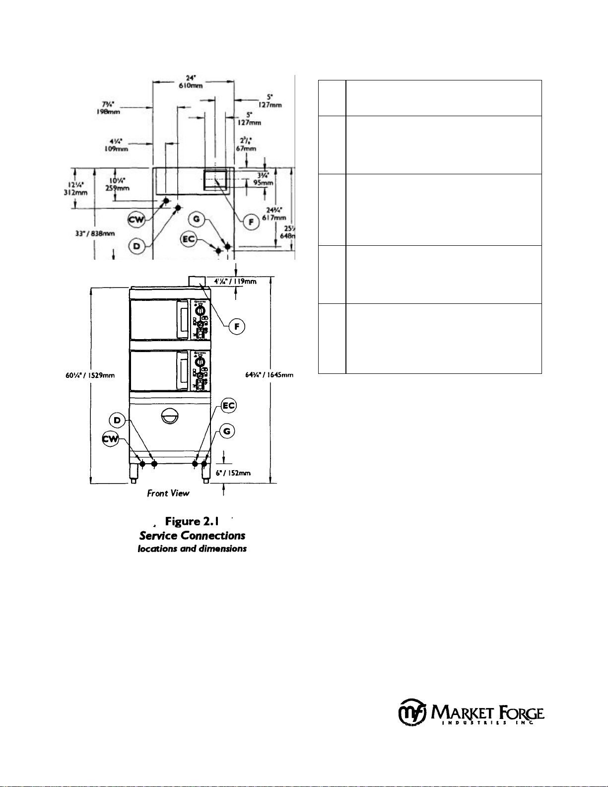
Table 2.1 Service
Connections
specifications and details
Gas Supply Connection-
G
1/2" NPT
Electrical Connection 120 VAC, 60hz, 1/2" conduit or equivalent.
Current draw for 120V control circuitry is 6.5
EC
Amps. Use wire suitable for at least 90°C.
Cold Water 1/2" NPT to cold water supply manifold. Cold
water supply line to have a maximum of 50 PSI
CW
(3.5 kg/cm2) and a minimum of 25 PSI (1.8
kg/cm2) water pressure.
Drain 1 1/2" 0. D. pipe coupled to 1 1/2" 0. D.
D
tempering tank drain. DO NOT MAKE SOLID
CONNECTION TO FLOOR DRAIN.
FluePlace unit so that the Flue is under an exhaust
F
hood to remove the products of gas combustion. DO NOT TOUCH FLUE! The Flue
reaches extremely high temperatures!
MARKET FORGE INDUSTRIES, INC.
35 GARVEY STREET EVERETT, MA 02149
TEL: 617 387 4100 TELEX: 94-9414 2.3
PAX: 6 I 7 387 4456 OUTSIDE MA 800 227 2659
1.4 SERVICE CONNECTIONS
All service connections are made at the bottom of
the unit, in the 6 inch high space between the floor and
the bottom of the cabinet. Please see Figure 2. 1 and
Table 2.1 for service connections, details and
dimensions.
NOTE:
If the equipment is to be installed where the
elevation exceeds 2,000 feet (609.6 meters) above
sea level, specify installation altitudes so that the
proper gas orifices can be provided.
Page 9

2. Installation
2.4.1 Water Connections
Before connecting water to this unit, have water
supply analyzed to make sure that hardness is no
greater than 2.0 grains per gallon and pH level is within
the range of 7.0 - 8.5. Water which fails to meet these
standards should be treated by the installation of a
water conditioner. EQUIPMENT FAILURE CAUSED
BY INADEQUATE WATER QUALITY IS NOT
COVERED UNDER WARRANTY.
CAUTION: PVC OR CPVC PIPING ARE NOT
ACCEPTABLE MATERIALS FOR USE IN DRAINS.
2.4.2 Electrical Connections
Connect cooker controls to 110/120 volt AC, 60
Hz, single phase branch circuit rated 15 amps capacity.
Wiring will conform to the requirements of national and
local electrical codes, (220 volts, 50Hz, single phase
for export units.
NOTE: ONLY A LICENSED ELECTRICIAN SHOULD
MAKE ELECTRICAL CONNECTIONS.
2.4.3 Gas Connections
Each of the generators are factory adjusted for a
gas input of 40,000 BTU/hr at the pressure indicated.
Please read the rating plate on the top of the unit. If
this plate is marked for a different gas than that
supplied, notify your dealer immediately. Install the
supplied external gas supply shut off valve at the gas
main inlet. This is located just under the bottom edge of
the lower front cover panel. Install so that the shut off
valve handle is clearly visible to the operator.
Use new iron or steel pipe complying with the
latest ANSI Standard for Wrought -Steel and Wroughtlron Pipe, B36, Properly threaded, reamed and free
from chips, oil, and dirt. If pipe dope is used, apply a
moderate amount leaving two end threads bare. Pipe
dope must be resistant to LP gas. Connect the gas line
into the bottom (inlet) side of the gas
MARKET FORGE INDUSTRIES, INC.
35 GARVEY STREET EVERETT. MA 02149 2.4
TEL: 61 7 387 4100 TELEX: 94-94 1 4
supply shut off valve. The supply pressure must be at
least I" (25mm) water column higher than the manifold
or regulator pressure for proper functioning of the
regulator. If it is not, check the supply pipe for blockage
or excessive pressure drop and make the necessary
corrections.
Perform a gas leak test of all newly -made joints,
as well as those leading to the main gas control valve.
Use a soap solution. DO NOT USE FLAME!
Natural gas units are equipped with a pressure
regulator factory adjusted to give 3.5" (89mm) water
column manifold pressure.
Propane gas units are equipped with a pressure
regulator factory adjusted to give 11" (279.5mm) water
column manifold pressure.
For conversion to either natural or propane
gas, 3 components must be changed. They are:
1. Gas orifices for each of the main burners.
2. Both complete pilot burners.
3. Springs inside each of the gas regulator
valves.
Consult the Market Forge for more detailed
information, instructions, and part numbers for
field conversion to either natural or propane gas.
NOTE: ONLY A LICENSED GAS FITTER SHOULD
MAKE GAS LINE CONNECTIONS.
2.4.4 Initial Systems Inspection
After the cooker is set in place, and all service
connections have been made, the cooker must be
given a final systems inspection prior to use. This is to
determine that all systems are functioning properly.
This procedure is described in full detail in Section 3,
"Initial Systems Inspection", of this manual. If all
systems perform as described in Section 3, the cooker
is ready for cooking use. If any of the systems are not
functioning as they should, consult Section 5,
"Troubleshooting" in this manual.
Page 10

2. Installation
2.5 REVERSING THE DOORS
The Steam Tech Plus Pressureless Steam
Cooker has cooking compartment doors which are
reversible, for your convenience. For Door Assembly
illustration and table, refer to pages 6.14 and 6.15.
9. Remove the two white hole plugs from the left
NOTE : This procedure is identical for both the
upper and lower cooking compartment doors.
1. Remove the left large side panel by removing the
screw from the center of the bottom edge of the
panel. Gripping one of the louvers, slide the
panel upwards until the bottom edge of the panel
is free to swing out slightly away from the unit.
Slide the panel down until its top edge is dear of
the top cap of the unit.
2. Open Cooking Compartment door.
3. Remove the two 5/16" bolts that attach the top
10. Rotate the door latch assembly 180°, and
install into the left door latch mounting holes.
NOTE : Each stud on the latch assembly should
have a plastic washer, a spring, a plastic washer
and a Nyloc type nut, as shown In Figure 6.5 on
page 6.14.
11. To adjust the tension of the door latch, tighten
hinge to the front of the unit.
4. Slide the door upwards, off the bottom hinge.
12. Replace large side panel by placing the panel
5. Remove the two 5/16" bolts that attach the bottom
hinge to the front of the unit.
NOTE: The top hinge is slightly larger than
the bottom hinge.
6. Remove the 4 black plastic hole plugs from the
front of the unit. Push the black hole plugs into
the now vacant left upper and lower hinge
13. Rotate the door 180° for mounting.
14. Slide the remaining (small) hinge into the top
mounting holes.
7. Reinstall the top (larger) hinge and bolts into the
15. Slide the door and hinge assembly down onto
right lower hinge mounting holes. Rotate the
hinge 180° for installation, so that the pin
which the door rides on is now facing up. The
hinge must be rotated because it will now
function as the bottom hinge. DO NOT
COMPLETELY TIGHTEN THE HINGE
MOUNTING BOLTS YET These will be used
later for adjusting the door.
MARKET FORGE INDUSTRIES, INC.
35 GARVEY STREET EVERETT, MA 02149 2.5
TEL: 617 387 4100 TELEX: 94-94 1 4
FAX: 0 1 7 387 4456 OUTSIDE MA 800 227 2659
16. Door Adjustment is covered in Section 6.8 on
8. Remove the door latch assembly from the
face of the unit. The 2 door latch mounting nuts
are located behind the face of the unit and must
be accessed by removing the large side panels.
door latch mounting holes, and insert them into
the right door latch mounting holes (where the
door latch assembly was originally mounted).
both nuts down until the springs are fully
compressed, then back each nut off 1/2 turn.
against the side of the unit. Be sure that the top
edge of the side panel slides under the top cap
of the unit. Slide the panel upwards until it stops.
Then, while pushing the panel in towards the
unit, slide it down into position. Replace screw.
door bearing.
the hinge which you have already mounted to
the front of the unit. Use the two 5/16" bolts to
mount the top hinge into the right upper hinge
mounting holes. DO NOT COMPLETELY
TIGHTEN THE HINGE MOUNTING BOLTS
YET. These are used later for door adjustment.
page 6. 12 of this manual.
Page 11
3.1 GENERAL
This section contains information for you to test
and familiarize yourself with the operation of the Steam
Tech Plus.
After the unit is completely assembled, all
packaging materials removed, and all service
connections are made, all systems must be given a
thorough check-out before being put into operation. Be
sure that the cooking compartments are empty, and all
pan support racks are in place. Confirm that all service
connections are on. Select a cooking compartment to
test. Close the cooking compartment door, and turn the
timer knob to the OFF position.
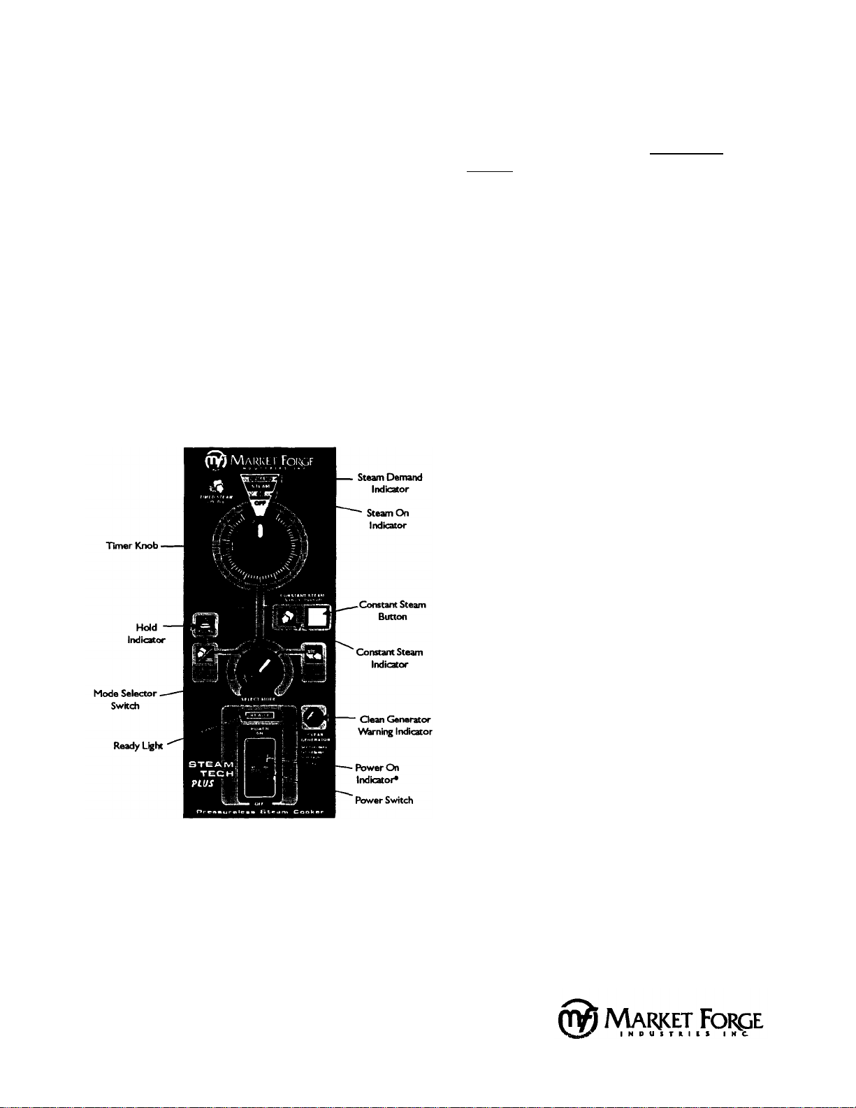
Figure 3. 1, below, illustrates the position of the
controls and Indicators for operation.
3. Initial Systems Inspection
NOTE: REPEAT STEPS IN SECTIONS 3.2
THROUGH 3.7 FOR BOTH THE UPPER AND
LOWER COOKING COMPARTMENTS TO INSURE
PROPER FUNCTIONING OF THE ENTIRE UNIT.
3.2 WARM-UP
Push the POWER switch Into the ON position.
The power light will come on immediately, along with
the fan motor. You will hear water entering the unit
through the solenoid valves, filling both the steam
generator and tempering tank.
Once the water levels in the steam generator
and tempering tank have reached the appropriate
level, the solenoid valves will close, and the burner
will Ignite. After a short time (approximately 5
minutes), the green READY light will come on,
indicating that the unit is ready to make steam.
3.3 STEAM DEMAND
Due to the unique nature of this design, it is
important to understand what the STEAM DEMAND
system does. The STEAM DEMAND syst em is the
means by which the Steam Tech Plus monitors and
creates steam. This system uses very sensitive sensors
to monitor the minute steam fluctuations inside the
cooking compartment. These fluctuations are an
indicator of how much steam energy the food inside the
cooking compartment is using. The sensor controls the
burner, Insuring that steam is created only as fast as it
will be accepted by the food inside the cooking
compartment, no more and no less.
This system can be monitored by observing the
red STEAM DEMAND indicator, located at the top of the
control panel. The STEAM DEMAND indicator will light
up red only when steam is called for, and will cycle on
and off throughout the cooking cycle.
Figure 3.1 Control Panel
• Note that your unit may come equipped with an independent POWER. ON
Indicator, located to the left of the Power Switch.
MARKET FORGE INDUSTRIES, INC.
35 GARVEY STREET EVERETT, MA 02149 3.1
TEL: 017 387 4100 TELEX: 94-94 1 4
FAX: 617 387 4456 OUTSIDE MA 800 227 2659
Page 12

3. Initial Systems Inspection
3.4 STEAM MODE
Turn the MODE SELECT switch to the STEAM
mode. Set the TIMER, knob to 10 minutes. Immediately, the STEAM ON window, located near the top of
the control panel, should light up green. At the same
time, the STEAM DEMAND window should light up red.
After a short time, the red STEAM DEMAND light will
begin to cycle on and off, while the green STEAM ON
light stays on continuously.
When the timer reaches 0 minutes, the buzzer
will sound, and both the STEAM ON and the STEAM
DEMAND lights will turn off. The buzzer is silenced by
returning the TIMER knob to the OFF position. The
green READY light will stay illuminated.
3.5 STEAM & HOLD MODE
Turn MODE SELECT switch to the STEAM &
HOLD mode. Set the TIMER knob to 10 minutes.
Immediately, the STEAM ON window, located near the
top of the control panel, should light up green. At the
same time, the STEAM DEMAND window should light
up red. After a short time, the red STEAM DEMAND
light will begin to cycle on and off, while the green
STEAM ON light stays on continuously.
When the timer reaches 0 minutes, the HOLD
window will light up amber. Both the STEAM ON and
the STEAM DEMAND lights will turn off. The green
READY light will stay Illuminated.
While the HOLD light is on, the cooking
compartment will function as a holding cabinet,
maintaining a safe food holding temperature of
approximately 160°F, indefinitely (as long as power is
supplied to the unit). Each of the cooking compartments has its own independent temperature gauge.
The cooking compartment temperature gauges are
mounted on the right hand side of the steam vent
hoods, directly above the control panel for each of the
cooking compartments.
3.6 CONSTANT STEAM MODE
The CONSTANT STEAM button overrides all
other cooking modes. When the CONSTANT STEAM
button is depressed, the CONSTANT STEAM window,
located next to the CONSTANT STEAM button, will
light up green. Immediately, the STEAM ON window,
located near the top of the control panel, should light up
green. At the same time, the STEAM DEMAND window
should light up red. After a short time, the red STEAM
DEMAND light will begin to cycle on and off, while the
green STEAM ON light remains illuminated
continuously.
NOTE : Even in the Constant Steam mode, the
generator will only create as much steam as will be
accepted by the food inside the cooking compartment.
No matter what mode has been selected, the red
STEAM DEMAND indicator will cycle on and off.
The generator will continuously make steam as
needed, until the CONSTANT STEAM button is
released (by pressing it again) and the green CONSTANT STEAM light goes off.
CAUTION: The timer is useful only as an alarm when in
the CONSTANT STEAM mode. The timer will count
down, but it will have no effect on the continuous
generation of steam, as it will be overridden by the
CONSTANT STEAM button.
3.7 STEAM SUPPRESSION
The proper operation of the Steam Suppression
system is evidenced by the lack of steam billowing out
of the cooking cavity when the door Is opened. While
the generator is creating steam, open the door to the
cooking compartment. As soon as the door is opened,
a solenoid valve will open, sending water to a spray
nozzle inside the steam generator. You should hear the
spray for approximately 3 to 4 seconds. At the same
time, both the STEAM ON and the STEAM DEMAND
lights will turn off. The green READY light will stay
illuminated.
MARKET FORCE INDUSTRIES, INC.
35 GARVEY STREET EVERETT, MA 02149 3.2
TEL: 617 387 4100 TELEX: 94-94 1 4
FAX: 6 17 387 4456 OUTSIDE MA 8OO 227 2659
Page 13

3. Initial Systems Inspection
Also, when the door is opened, any residual steam
will be drawn up into the steam vent hood. The steam
vent hoods are located above each cooking
compartment
When the door is closed, the STEAM ON and the
STEAM DEMAND windows will light up again. At the
same time, a bubbling sound may be heard, as the cool
air is evacuated from the cooking compartment and
replaced with fresh steam from the generator. The unit
will continue to cycle normally, as it was before the door
was opened.
NOTE: REPEAT STEPS IN SECTIONS 3.2
THROUGH SECTION 3.7 FOR BOTH THE UPPER AND
LOWER COOKING COMPARTMENTS TO INSURE
PROPER FUNCTIONING OF THE ENTIRE UNIT
BEFORE PROCEEDING TO THE NEXT PARAGRAPH,
(3 8 SHUTDOWN).
3.8 SHUTDOWN
No special procedure is necessary for shutting the
unit down. Simply press the POWER switch into the OFF
position. All indicator lights on the control panel will go out,
and the generator for that cooking compartment will drain.
The tempering tank will not drain until both POWER
switches are in the OFF position
CAUTION: When the unit is not in use, leave both
cooking compartment doors slightly ajar to extend the
life of the cooking compartment door gaskets.
Please note that the TIMER should be in the OFF
position and the CONSTANT STEAM button should be
disengaged upon restarting the unit to avoid any
unintentional generation of steam on startup.
NOTE: As a final test of the unit before use in
cooking food, both generators should be shut down,
allowing both the generators and tempering tank to
completely drain.
MARKET FORGE INDUSTRIES INC
35 QARVEYSTREET EVERETT. MA 02149
TEL 0173874100 TELEX 949414
FAX 6 1 7 387 4456 OUTSIDE MA 800 227 2659
Page 14

4. Operation
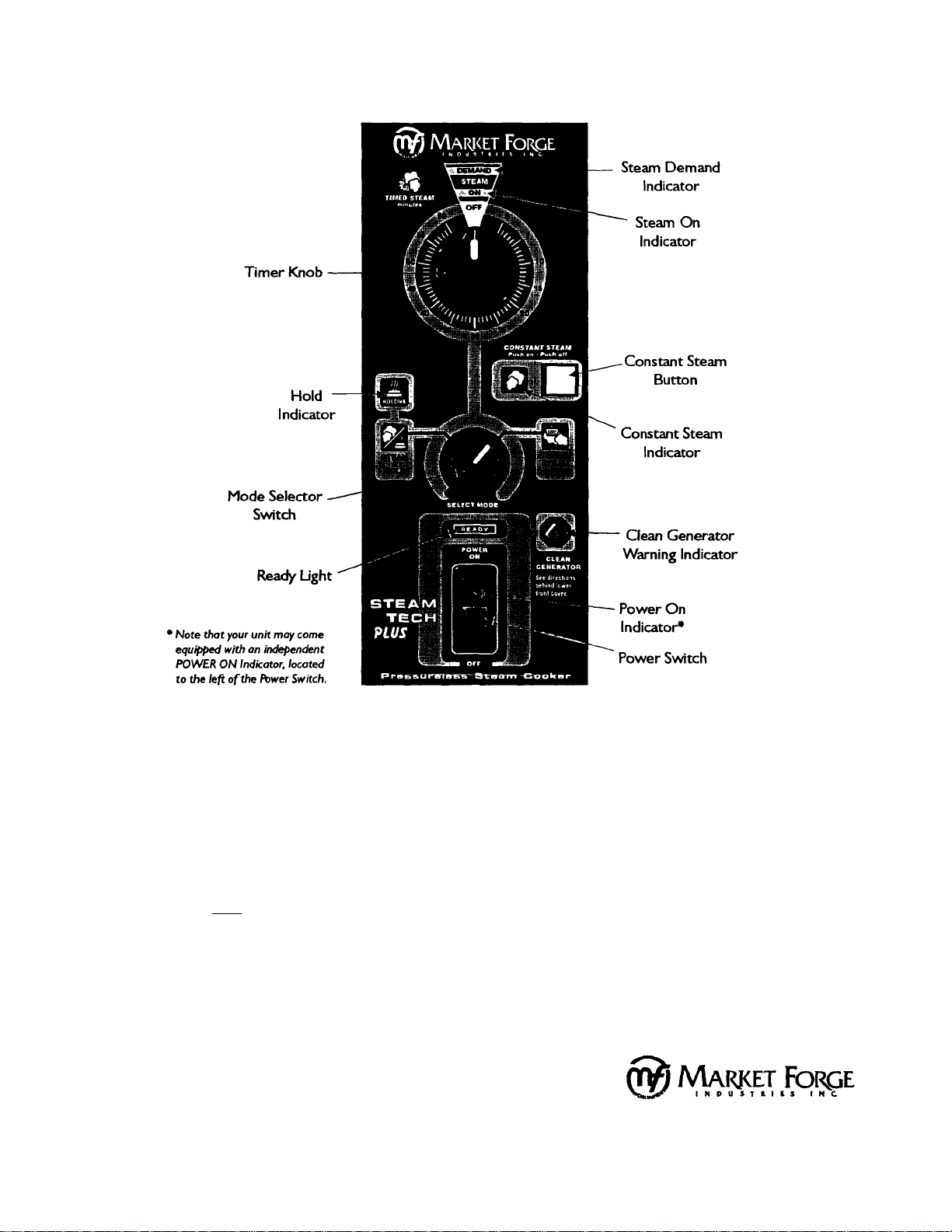
4.1 CONTROLS AND INDICATORS
The controls and indicators used to operate the Steam
Tech Plus pressureless steam cooker are listed and described
in Table 4.1, on page 4.3. Their locations are called out in
Figure 4.1, on page 4.2.
4.2 OPERATING PROCEDURES
1. Slide pans of food into the cooking compartment
pan support racks.
2. Firmly close the cooking compartment door.
3. Select a cooking cycle, either timed or untimed.
4. For timed cooking, set the MODE SELECT switch
to the desired cooking mode and set the TIMER,
to the desired cook time.
This section includes general instructions for daily
operation of the Steam Tech Plus pressureless steam
cooker. You should review Section 3.1 through
Section 3.8 of this manual if you are unfamiliar with the
functions of the Steam Tech Plus. If you require more
detailed technical information on the Steam Tech Plus'
various systems and their functions, please consult
your Market Forge Factory Authorized Service Agency
Representative.
4.2.1 Start-up and Preheating
The Steam Tech Plus pressureless steam cooker
requires no start-up procedure. Simply press the
POWER switch into the ON position. The ignitor will
attempt to ignite the burner for up to 90 seconds, If
after 90 seconds, the burner hasn't ignited, the gas
ignition control will go into lockout. The system will
then need to be manually reset by pressing the
POWER switch into the OFF position for 5 minutes.
Wait 5 minutes before turning the unit on again.
The tempering tank and selected cooking
compartment's steam generator will fill with water.
Once full, the burner will automatically preheat the
water in the generator to 193°F. This will take
approximately 7 minutes. When the generator is ready
to create steam, the green READY light will come on.
4.2.2 Cooking
NOTE : The green READY light must be on
before any controls become operational.
5. At the end of a timed cook cycle (when the timer
has timed out to zero), return the TIMER knob to
the OFF position to:
a. Silence the buzzer (when using the
STEAM Mode).
b. Exit the HOLD function (when using the
STEAM & HOLD Mode).
6. For untimed cooking, press the CONSTANT
STEAM button to override the TIMER and create
continuous untimed steam.
7. When using the untimed cooking cycle, and you
have determined that the food in the cooking
compartment is done, press the CONSTANT
STEAM button again to exit the CONSTANT
STEAM Mode.
8. In any cooking cycle or mode, the Steam
DEMAND light will cycle on and off. This indicates
the automatic creation of steam as it is called for
by the food being cooked.
CONDENSATE WARNING:
Normal steam cooking conditions will create
some condensate due to temperature differences
between the steam and the objects/surfaces it
contacts. When an excessive volume of
condensate appears in the cooking compartment,
the steam generator water level control should be
checked for possible malfunction and the need for
maintenance. Continued use of the equipment,
without maintenance, will create a potential for
scalding.
MARKET FORGE INDUSTRIES, INC,
35 GARVEY STREET EVERETT, MA 02149 4.1
TEL-6173874100 TELEX: 94-94 1 4
FAX: 617 387 4456 OUTSIDE MA 800 227 2659
Page 15
4. Operation
Figure 4. 1
Control Panel
4.2.3 Shut-down
No Shut Down procedure is required for the
Steam Tech Plus. Simply press the POWER Switch
into the OFF position. When shut down, all indicator
lights on the control panel for that cooking compartment will go out, and the generator for that compartment will automatically drain. The tempering tank
will not drain until both POWER switches ore in the
OFF position.
MARKET FORGE INDUSTRIES, INC.
35 GARVEY STREET EVERETT, MA 02149
TEL: 617 387 4100 TELEX: 94-9414 4.2
FAX: 6 I 7 387 4456 OUTSIDE MA 800 227 2659
When a cooking compartment Is not in use, be
sure to leave its door slightly ajar to extend the life of
the cooking compartment door gasket. When the unit is
completely shut down, both cooking compartment
doors should be left ajar.
NOTE : To avoid the unintentional creation of
steam upon startup, return both timer knobs to the OFF
position and be sure that both CONSTANT STEAM
switches are disengaged.
Page 16
4. Operation
supply power to unit and activate the corresponding system. Pressing this switch into the
Located in the center of the control panel, just above the ready light. Turn the switch to the
Located above the Steam On indicator. Lights up red as the product you are cooking calls
Located at the bottom of the control panel. Pressing this switch into the ON position will
Power Switch
OFF position will cut off power to the corresponding system and shut down the unit.
Power Indicator
Ready Light
Mode Selector Switch
Timer Knob
Steam On Indicator
Steam Demand Indicator
Hold Indicator
Temperature Gauge
Located in the body of the POWER SWITCH. Lights up red when the POWER SWITCH Is
pressed into the ON position.
Located above the POWER SWITCH. Lights up green when the corresponding generator
has warmed up, indicating that it is ready to create steam.
right to select the STEAM mode. Turn the switch to the left to select the STEAM & HOLD
mode.
Located near the top of the control panel. Turn the timer knob clockwise to set the cook
time.
Located near the top of the control panel. Lights up green when any cooking mode is
active.
for steam. It will cycle on and off at varying rates depending on the quantity and product
being cooked.
Located near the center of the control panel, on the left side. Lights up amber when the
unit is in the HOLD mode.
Located on the right side of each of the steam hoods, above the control panel. They are
used to monitor the internal temperature of the cooking compartments during the HOLD
mode.
Located near the center of the control panel, on the right side. Press the button once to
Constant Steam Switch
Constant Steam Indicator
Clean Generator Warning
Indicator
engage it and enter the CONSTANT STEAM mode. Press it again to disengage it and exit
the CONSTANT STEAM mode.
Located next to the Constant Steam button. Lights up green whenever the unit Is in the
CONSTANT STEAM mode.
Located in the lower right side of the control panel. This will light up red when the
generator needs to be de-limed.
Table 4.1
Controls and Indicators
MARKET FORGE INDUSTRIES, INC.
35 GARVEY STREET EVERETT, MA 02149 4.3
TEL: 6 17 387 4100 TELEX: 94-94 I 4
FAX: 6 I 7 387 4456 OUTSIDE MA 800 227 2659
Page 17

4 1 Left Pan Slide
E91-5700
4. Operation
Table 4.2 - Daily Cleaning Parts List, (single cooking compartment shown*)
ITEM QTY.* DESCRIPTION PART NO.
1 1 A-la-carte Tray E91-5782
2 1 Cooking Compartment Drain Screen E91-5718
3 1 Drip / Spill Trough Screen E91-5769
5 1 Right Pan Slide E91-5698
*NOTE The components and quantities shown on this page are for a single cooking compartment only. These
components and quantities are identical for both the upper and lower cooking compartments.
MARKET FORGE INDUSTRIES, INC.
35 GARVEY STREET EVERETT, MA 02149 4.4
TEL: 617 387 4100 TELEX: 94-94 I 4
FAX. 6 1 7 387 4456 OUTSIDE MA 800 227 2659
Page 18

4. Operation
4.3 DAILY CLEANING
After each period of daily operation (more frequently as
required to maintain cleanliness) the cooker should be
thoroughly cleaned by completing the following steps:
1. Remove the left and right side pan support racks by
lifting them up off their mounting brackets.
2. Remove the a-la-carte tray from the floor of the
cooking compartment by lifting the front of the tray
off the mounting pins and sliding it forward.
3. Remove the drain screen from the rear wall of the
cooking cavity by sliding it up off its mounting tabs.
4. Wash cooking compartment interior using detergent
and water. Rinse and dry thoroughly.
5. Remove upper and lower Drip/Spill Trough screens.
Lift the left side of the screen up and swing it out
away from the face of the unit until it Is free to slide
out from under the control panel housing.
6. Wash all removed pieces with a detergent, using a
brush, and rinse. These pieces can also be sent
through a commercial automatic dishwashing
machine. Set these pieces aside for reassembly.
9. Replace a-la-carte tray by sliding it back until it drops
down onto its mounting pins.
10. Replace pan supports into cooking cavity by
hanging them on their mounting brackets. 8e sure
to hang the support with the metal baffling on it on
the right (steam inlet opening) side of the cooking
cavity.
4.4 PROLONGED SHUT-DOWN AND CLEANING
1. Press the both POWER switches into the OFF position. The
steam generators and tempering tank will automatically
drain.
2. Clean the cooking compartment, as described in Section
4.3 of this manual.
3. The Steam Generator must be Rinsed & Drained. Refer to
Section 6.4, Cleaning the Generator, for complete
instructions.
4. Turn gas valve to the OFF position.
CAUTION:
7. Replace the Drip/Spill Trough screens by sliding the
right hand side of the screens under the control
panel housing. Then swing the left hand side of the
screen in towards the face of the unit until the
screen is free to drop down into position.
8. Replace drain screen onto rear wall of cooking
compartment by sliding it down onto its mounting
tabs.
• Disconnect the power supply to the steam generators
before servicing.
• Keep appliance area free & clear from combustibles.
• Don't obstruct the flow of combustion & ventilation air.
• Contact the factory, the factory representative, or a factory
authorized service company to preform maintenence and
repairs.
• In the event of a power failure, no attempt should be made
to operate this appliance. Be sure both power switches are
in the OFF position.
• Keep this manual for daily reference.
MARKET FORGE INDUSTR IES, INC.
35 GARVEY STREET EVERETT, MA 02149 4.5
TEL: 617 387 4100 TELEX: 94-9414
FAX: 017 387 4456 OUTSIDE MA 800 227 2659
Page 19

Water enters the steam generator
5. Troubleshooting
5.1 GENERAL
The information in this section is intended to assist the
operator, maintenance and the service personnel in locating
the source of problems which may occur with the cooker.
Before following any of the procedures given in this section,
the operator/maintenance person should be thoroughly
familiar with the "Operation" Section of this manual.
TROUBLE POSSIBLE CAUSE REMEDY
POWER Light does not come on
when the POWER Switch is
pressed into the ON position.
1. No 120v power to unit.
2. Fuse blown.
3. Faulty POWER Switch.
If the problem cannot be readily corrected without the
use of tools, the operator/maintenance person should contact
the nearest Market Forge service agency for assistance.
1. Be sure 120v power supply is on.
2. Replace fuse.
3. Check/replace POWER Switch.
1. Dirty strainer screen in the water fill solenoid
and/or tempering tank very slowly.
Steam generator will not fill.
Tempering tank will not fill. 1. Fuse blown.
valve.
2. Dirt or lime accumulation on seat of water fill
solenoid valve.
1. Faulty generator fill solenoid valve. 2. Faulty
generator drain solenoid valve.
2. Faulty tempering tank fill/cool solenoid valve.
3. Faulty tempering tank drain solenoid valve.
1. Clean/replace strainer screen.
2. Clean valve seat.
1. If 120 Volt is verified at the solenoid
coil, but the valve fails to open, replace
solenoid.
2. If 120 Volt is verified at the solenoid
coil, but the valve fails to close, replace
solenoid.
1. Replace fuse.
2. If 120 Volt is verified at the solenoid
coil, but the valve fails to open, replace
solenoid.
3. If 120 Volt is verified at the solenoid
coil, but the valve fails to close, replace
solenoid.
MARKET FORCE INDUSTRIES, INC.
35 GARVEY STREET EVERETT, MA 02149 5.1
TEL: 617 387 4100 TELEX: 94-94 1 4
FAX: 6 17 387 4456 OUTSIDE MA 800 227 2659
Page 20

5. Troubleshooting
Make sure that the manual safety gas
lator gas
Be sure ignitor is seated properly in its
TROUBLE POSSIBLE CAUSE REMEDY
Warm-Up Burner will not ignite. 1. No gas supply to unit. 1. Make sure that gas service is
connected and turned on.
2. No gas supply to gas regulator valve. 2.
valve is turned on.
3. No gas supply beyond gas regulator valve. 3. Make sure that the main regu
valve is turned on.
4. Faulty Warm-up burner solenoid valve in gas
regulator.
4. If 24 volts is verified at the solenoid
coil, but valve fails to open, replace gas
regulator.
5. Faulty ignition/flame sensor control module. 5. See Ignition/Flame Sensor Control
Diagnostic section.
6. Faulty ignitor. 6. Check electrical connections.
* Be sure ignitor gap is 1/8".
* Check ignitor alignment.
* Be sure ignitor is seated properly in
its mounting.
Warm-Up Burner will not stay lit. 1. Faulty ignition/flame sensor control module. 1. See Ignition/Flame Sensor Control
Diagnostic section.
2. Faulty ignitor/flame sensor. 2. * Check etectrical connections.
*Be sure ignitor gap is 1/8".
*Check ignitor alignment.
*
mounting.
3. Sediment trap may be full. 3. Empty sediment trap. Be sure to turn
off main gas supply!
READY light will not come on. 1. Faulty 190°F generator thermostat. 1. Check/replace 190°F generator
thermostat.
MARKET FORGE INDUSTRIES, INC.
35 GARVEY STREET EVERETT, MA 02149 5.2
TEL: 6 17 387 4100 TELEX: 94-94 1 4
FAX: 617 387 4456 OUTSIDE MA 800 227 2659
2. Faulty READY light. 2. Check/replace READY light.
Page 21

5. Troubleshooting
(Main Burner will not ignite, STEAM
* Be sure ignitor is seated properly in its
coil, but valve fails to open, replace gas
TROUBLE POSSIBLE CAUSE REMEDY
Generator will not create steam
ON light does not come on).
1. Cooking compartment door is ajar.
2. Cooking compartment door out of
alignment.
1. Check to be sure that the cooking
compartment door is closed and
latched.
2. Check to be sure cooking
compartment door is properly aligned.
3. Faulty door magnet or magnetic reed switch. 3. Check magnet and reed switch.
Replace if necessary.
4. Faulty ignition/flame sensor control module, 4. See Ignition/Flame Sensor Control
Diagnostic section.
5. Faulty ignitor. 5. * Check electrical connections.
* Be sure ignitor gap is 1/8".
* Check ignitor allignment.
mounting.
6. Faulty Main burner solenoid on gas regulator
valve relay.
7. Faulty Main burner solenoid on gas regulator
valve.
6. Check Main burner solenoid relay.
Replace if necessary.
7. If 24 volts is verified at the solenoid
regulator.
8. Faulty pressure switch. 8. Check/replace pressure switch if
necessary.
9. Faulty control panel TIMER 9. Check/replace control panel TIMER if
necessary.
10. Faulty MODE SELECT Switch. 10.Check/replace MODE SELECT
11. Faulty CONSTANT STEAM Button. 11 .Check/replace CONSTANT
MARKET FORGE INDUSTR IES, INC.
35 GARVEY STREET EVERETT, MA 02149 5.3
TEL: 6 17 387 4100 TELEX: 94-94 1 4
FAX: 6 1 7 387 4456 OUTSIDE MA 800 227 2659
switch if necessary.
STEAM button if necessary.
Page 22

TROUBLE POSSIBLE CAUSE REMEDY
Loss of water seal due to low water or no water
r
Generator continuously creates
steam (Steam DEMAND light is
always on).
1. Cooking compartment door out of
alignment.
2. Cooking compartment door gasket leaky.
1. Check alignment of door.
Realign if necessary.
2. Check/replace door gasket.
Steam Suppression not
functioning. ( Excess steam
comes out of the cooking
compartment when the door is
opened.)
3. Pressure switch disconnected. 3. Check to be sure all pressure switch
connections are made.
4. Faulty pressure switch (contacts failed closed). 4. Check/replace pressure switch.
5. Leaky cooking compartment drain line. 5. Check to be sure cooking
compartment drain line is sealed.
Replace if necessary.
6. Steam trap failed open.* 6. Check/replace steam trap.
7.
in tempering tank.*
1. Dirty strainer screen in the spray nozzle
solenoid valve.
2. Dirt or lime accumulation in the generator
spray nozzle.
3. Faulty timer which controls spray nozzle wate
solenoid valve.
7. See "Tempering tank will not fill"
section, on page 5.1 of this manual.
1. Clean or replace strainer
screen.
2. Clean generator spray nozzle.
3. Check to be sure that timer is set
properly, and works. If it doesn't work,
replace it.
4. Misaligned ventilation ductwork. 4. Check ductwork and realign where
5. Blower not running. 5. Check/replace fuse. Be sure that the
6. Faulty wiring. 6. Check wiring.
• If this is the problem, you will also notice excess amounts of steam coming out the vent tube at the top of the unit.
MARKET FORGE INDUSTRIES, INC.
35 GARVEY STREET EVERETT, MA 02149 5.4
TEL! 6 1 7 387 4 1 00 TELEX: 94-94 1 4
FAX: 617 387 4456 OUTSIDE MA 800 227 2659
necessary.
blower motor works.
If not, replace blower.
Page 23

TROUBLE POSSIBLE CAUSE REMEDY
Generator doesn't drain when the
to the
Tempering tank doesn't drain when
ter it has been cleaned (delimed)
Check to be sure timer is set correctly.
Generator continues to create
steam when the cooking
compartment door is opened.
Tempering tank drain water
temperature too high.
POWER Switch is pressed in
OFF position.
1. Faulty magnet reed switch (contacts failed
closed).
2. Faulty wiring.
1. Faulty 130°F thermostat in the tempering
tank.
2. Faulty tempering tank fill/cool solenoid valve.
3. Faulty wiring.
1. Clogged or kinked generator drain line.
2. Clogged generator drain hole. 3. Faulty
generator solenoid drain valve.
1. Check magnetic reed switch.
Replace if necessary.
2. Check wiring.
1. Check 130°F thermostat.
Replace if necessary.
2. If 120 Volt is verified at the solenoid
coil, but the valve fails to open, replace
solenoid.
3. Check wiring.
1. Check to be sure that the generator
drain line is not kinked and is free of
debris.
2. Check to be sure the generator drain
hole is free of debris.
3. Rebuild or replace generator
solenoid drain valve.
1. Clogged tempering tank drain line.
both POWER Switches are in the
OFF position.
2. Clogged tempering tank drain hole.
3. Faulty tempering tank solenoid drain
valve.
CLEAN GENERATOR light stays on
af
and rinsed.
1. Faulty or incorrectly set CLEAN
GENERATOR timer.
2. Faulty CLEAN GENERATOR relay.
3. Faulty wiring.
MARKET FORGE INDUSTRIES, INC.
35 GARVEY STREET EVERETT, MA 02149 5.5
TEL; 0 1 7 387 4 1 00 TELEX. 94-94 1 4
FAX: 617 387 4456 OUTSIDE MA 800 227 2659
1. Clean or replace tempering tank
drain line.
2. Check to be sure that the
tempering tank drain hole is free of
debris.
3. Rebuild or replace tempering tank
solenoid drain valve.
1.
Replace if necessary.
2. Check/replace if necessary.
3. Check wiring.
Page 24

5. Troubleshooting
5.2 WATER LEVEL CONTROL BOARD
The Dual Function Water Level Controller is two
controls on one board. One controller maintains correct
water level in the boiler, the other a low water safety
cutoff.
The following troubleshooting procedure will only
determine if the Water Level Control Board is working
properly, it will not determine why the board has failed.
This procedure exposes you to a shock hazard and
must be performed only by qualified service personnel.
NOTE: Improperly connected or malfunctioning water
level controller may cause damage to the steam
generator due to low water, or create a scalding hazard
to the operator due to a hot water overflow condition.
Tools Required:
A digital or analog volt meter capable of reading 120
volts A.C. and a jumper wire with alligator clips.
MARKET FORGE INDUSTRIES, INC
35 GARVEY STREET EVERETT, MA 02149 5.6
TEL 6173874100 TELEX 94-9414
FAX 6173874456 OUTSIDE MA 800 227 2659
Procedure:
1. Turn off all power to the unit.
2. Select the controller to be tested. Inside the electrical
panel, the water level control for the top cooking cavity
is at the top of the electrical panel and wires to the
controller will have an "A" after the wire number. The
controller for the bottom cooking cavity is at the bottom
of the electrical panel and its wires will have a "B" suf fix. In this test procedure, reference to the wires' "A" or
"B" suffix will be omitted.
3. Remove the wires #40,41, and 42 from the terminal
connectors "G", "H", and "LLOC".
WARNING: When you turn the power on, there are
terminals that carry 120 volts. Protect the ends of these
disconnected wires to prevent snorting to hot /eads.
4. Turn power ON. Using the voltmeter, check that
power being supplied to terminals L I & L2 is 120 volts,
plus 10%, minus 15%.
Page 25

6. Maintenance
6.1 GENERAL
This section contains both preventive and
corrective maintenance information. Preventive
maintenance may be performed by maintenance
personnel at the establishment In which the cooker is
installed. It is recommended that user personnel never
attempt to make repairs or replacements to the
equipment. Assistance in service methods or a current
directory of authorized agencies may be obtained from
Market Forge Industries.
6.2 DAILY CLEANING
After each period of daily operation (more
frequently as required to maintain cleanliness) the
cooker should be thoroughly cleaned by completing the
following steps:
Procedure:
1. Remove the left and right side pan support
racks by lifting them up off their mounting
brackets.
2. Remove the a-la-carte tray from the floor of the
cooking compartment by lifting the front of the
tray off the mounting pins and sliding it
forward.
4. Wash cooking compartment interior using
detergent and water. Rinse and dry thoroughly.
5. Remove upper and lower Drip/ Spill Trough
screens. Lift the left side of the screen up and
swing it out away from the face of the unit
until it is free to slide out from under the
control panel housing.
6. Wash all removed pieces with a detergent,
using a brush, and rinse. These pieces can
also be sent through a commercial automatic
dishwashing machine. Set these pieces aside
for reassembly.
7. Replace the Drip/Spill Trough screens by
sliding the right hand side of the screens
MARKET FORGE INDUSTRIES, INC.
35 GARVEY STREET EVERETT, MA 02149 6.1
TEL: 6 17 387 4100 TELEX: 94-94 1 4
FAX: 6 17 387 4456 OUTSIDE MA BOO 227 2659
under the control panel housing.
Then swing the left hand side of the screen in
towards the face of the unit until the screen is
free to drop down into position.
8. Replace drain screen onto rear wall of cooking
compartment by sliding it down onto its
mounting tabs.
9. Replace a-la-carte tray by sliding it back until it
drops down onto its mounting pins.
10. Replace pan supports into cooking cavity by
hanging them on their mounting brackets. Be
sure to hang the support with the metal
baffling on it on the right (steam inlet
opening) side of the cooking cavity .
6.3 PREVENTIVE MAINTENANCE
A good preventive maintenance program begins
with the daily cleaning procedure described above,
along with examinations of the flue and ventilation
systems to be sure they are free of any obstructions.
NOTE: Your unit may be equipped with a blower
motor which requires lubrication. Check the information
plate located on the side of the blower motor for
lubrication instructions. The blower assembly is located
inside the unit, mounted to the rear center of the floor
pan.
Additional preventive maintenance operations are
presented in this section. In establishments which
employ full-time maintenance personnel, the tasks
described can be assigned to them. For other
installations, tasks requiring mechanical or electrical
experience mu st be performed by an authorized service
agency.
CAUTION: Under no circumstances should
hardware (or parts) be replaced with a different size
or type other than as specified in the parts list. The
hardware used in the cooker has been selected or
designed specifically for its application and the use
of other hardware may damage the equipment,
present a safety hazard and will void any warranty.
Page 26

6. Maintenance
Table 6. 1 - Exterior Sheetmetal Cover Panels and Fasteners Ports List
ITEM QTY. DESCRIPTION PART NO.
1 4 Leg, black, adjustable El 0-0631
2 1 Front Cover Panel Assembly E91-5767
3 1 Rear Cover Panel Assembly E91-5789
4 1 Removable Vent Hatch E91-5777
5 2 Side Cover Panel Assembly E9I -5778
Fasteners 22 8-32 slotted truss head machine screw, 3/8" long, stainless steel E08-3492
MARKET FORGE INDUSTRIES, INC
35 GARVEYSTREET EVERETT, MA 02149
TEL 617 387 A 100 TELEX: 94-94 I 4 6.2
FAX 61 7 387 4456 OUTSIDE MA 800 227 2659
Page 27

The following sections set forth minimum
preventive maintenance procedures which must be
completed periodically to assure continued trouble free
operation.
6.4 CLEANING THE GENERATOR
The Steam Tech Plus Pressureless Steam
Cooker has an automatic indicator light which tells you
when the steam generator needs to be cleaned. When
the CLEAN GENERATOR light comes on, the
generator remains fully functional until it is shut down.
This will allow you to continue to use the unit for the
remainder of the day, until you shut it down. The next
time the unit is turned on, the generator will fill and
preheat to 190°F, but it will not create steam. The
CLEAN GENERATOR light will remain illuminated. The
steam generator must be cleaned before it will create
steam again.
6. Maintenance
protective hand covering. DO NOT TRY TO
REACH INTO THE OPEN SIDE WALL PORTS
This opening is directly connected to the
steam generator.
3. Pour 1/2 gallon of Market Forge's TOTAL CONCEPT™ de-liming solution directly into the open
side wall port. This will immerse the generator
interior and water level probes in the solution.
CAUTION: Read directions and information on
TOTAL CONCEPT™ de-liming solution before using.
4. Wait two hours for TOTAL CONCEPT™ de-liming
solution to work. (Other de-liming solutions may
take much longer.)
5. Make sure the cooking compartment door is
unlatched and slightly ajar, then press the
RINSE & DRAIN button for the generator being
cleaned. (The RINSE & DRAIN buttons are
located on the front of the electrical box, inside
the unit. See Figure 6.1 on page 6.2)
6.4.1 Cleaning Instructions
These cleaning instructions can also be found
printed on the sticker, on the top of the electrical box
inside the unit.
In order to perform this procedure, you will need
TOTAL CONCEPT™ de-liming solution. (Market Forge
Pan Number 20-0307.)
Procedure:
1. Leave the POWER switch on, and wait for the
green READY light.
2. Remove the right pan support rack from inside the
cooking compartment to reveal the side wall
opening
CAUTION: The steam generator and pipe
fittings reach 190°F during the preheat cycle.
Use caution and wear
MARKET FORGE INDUSTRIES, Inc.
35 GARVEY STREET EVERETT, MA 02149
TEL: 017 387 4100 TELEX: 94-94 1 4 6.3
FAX: 61 7 387 4456 OUTSIDE MA 800 227 2659
This will start the draining and spray rinsing of the
steam generator. The RINSE & DRAIN cycle will run for
approximately 3 minutes. At the end of the RINSE &
DRAIN cycle, the steam generator will automatically
refill and warm up.
IT IS NOT NECESSARY TO RINSE & DRAIN
MORE THAN ONCE. The rinsing spray inside the
steam generator will remove all traces of the de-liming
solution.
NOTE: When the steam generator is clean, the
CLEAN GENERATOR light will go off as soon as the
green READY light comes on.
CAUTION: If, after cleaning the steam generator, the
CLEAN GENERATOR light is still on after warm-up
(when the READY light comes on), there may be an
electrical problem. See page 5.5 of the Troubleshooting
section of this manual. Consult with qualified service
personnel for test and repair.
Page 28

6. Maintenance
6.5 CLEANING THE STEAM
VENTILATION DUCTWORK
The Steam Tech Plus steam ventilation ductwork
system is made up of a series of horizontal and vertical
ducts. This series of ductwork must be cleaned
periodically, in order to maintain cleanliness.
Frequency will vary according to use. The recommended procedure for cleaning of the steam ventilation
ductwork is contained in this section.
NOTE: In order to perform this procedure, you
must gain access to the rear of the unit.
Procedure:
1. Turn off the Main gas supply and disconnect the
gas service connection.
2. Disconnect the 120v power supply.
3. Slide the unit out, away from the wall. (You may
need to disconnect the water inlet line.)
7. Using detergent and a damp cloth, wipe clean
the inside of the vent access hatch.
8. Reinstall vent access hatch onto rear of unit.
9. Using detergent and a damp cloth, wipe clean the
inside of the upper and lower steam vent hoods,
located on the front of the unit, just above each
of the cooking compartments.
10. Reconnect 120v power supply.
11. Reconnect the gas service connection and turn
the Main gas supply back on.
12. Slide the unit back into place.
NOTE: You may need to relevel the unit, as
described in step 5 of Section 2.1.
13. If you hav e disconnected the water inlet line,
reconnect it now.
4. Remove the 11 screws which hold the louvered
vent access hatch onto the rear panel of the
unit. (Refer to Figure 6.1 on page 6.2.)
5. Using detergent and a damp cloth, wipe clean the
inside of both the upper and lower horizontal
intake ducts, located just above the cooking
compartments. The very front of these ducts
may be accessed more easily from the front of
the unit.
6. Using detergent and a damp cloth, wipe clean the
inside of both the vertical intake and exhaust
ducts. These ducts are mounted onto the Inside
of the rear panel of the unit.
CAUTION: When cleaning the vertical
exhaust duct, be very careful not to damage
the blower, which is located at the bottom of
this duct. Looking at the unit from the rear,
the vertical exhaust duct is the one on the
right..
6.6 ELECTRICAL BOX SERVICE ACCESS
The Steam Tech Plus electrical box is located
behind the lower front panel of the unit. Most major
electrical componentry is mounted onto the inside of
the electrical box.
CAUTION: Be sure to disconnect BOTH power
supplies from the unit before servicing any
electrical componentry.
To gain access to the electrical box, the lower
cover panel must be removed from the front of the unit.
Prior to removing this panel, the lower drip/spill trough
screen must be removed. Gripping the round handle,
slide the panel upwards until it stops, and pull it out
away from the unit. This will reveal the hinged
electrical box. Unscrew the captive screw latch, which
is located on the left si de of the electrical box and
swing the electrical box open to access the electrical
componentry for service.
MARKET FORGE INDUSTRIES, INC.
35 GARVEY STREET EVERETT, MA 02149 6.4
TEL: 617 387 4100 TELEX: 94-94 1 4
FAX: 6 17 387 4456 OUTSIDE MA 800 227 2659
Page 29

6. Maintenance
5 2 Control Board
08-6536 1
1 2 Terminal Block
08-6518
Figure 6.2 - Electrical Panel Assembly
Table 6.2 - Electrical Panel Assembly Parts List
ITEM
QTY.
1
2 1 Fuse Block 08-6520 8 2 Signal Transformer 08-6450
3 2 Gas Ignition Control 08-6542 9 2 Push Button Switch 08-6517
4 1 Grounding Lug 10-5220 10 1 Terminal Block Assembly 08-6519
6 4 DIN Rail Retainer Clips 08-6516 12 4 Relay, SPDT 10-9174
DESCRIPTION
2
Relay Mounting Rail
PART NO.
08-6515
ITEM
7
QTY
4
DESCRIPTION
Relay Socket
PART NO.
10-9175
MARKET FORGE INDUSTR IES, INC
35 GARVEY STREET EVERETT, MA 02149 6.5
TEL 617 387 4100 TELEX 94-9414
FAX 6173874456 OUTSIDE MA 800 227 2659
Page 30

6. Maintenance
Principles of Operation Schematic
MARKET FORGE INDUSTRIES. INC
35 GARVEY STREET EVERETT.MA 02149
TEL: 6 I 7 387 4 100 TELEX: 94-94 I 4
FAX: 617 387 4456 OUTSIDE MA 800 227 2659
Page 31

6. Maintenance
MARKET FORGE INDUSTRIES. INC.
35 GARVEY STREET EVERETT.MA 02149
TEL.: 61 7 387 4100 TELEX: 94-94 1 4
FAX! 0 I 7 387 800 OUTSIDE MA 800 227 2659
Single Compartment System Wiring Diagram
Page 32

6. Maintenance
Single Compartment System Wiring Diagram
MARKET FORGE INDUSTRIES. 1NC-
35 GARVEY STREET EVERETT. MA 02149
TEL: 617 387 4100 TELEX: •94-9414 6.9
FAX: 617 387 4456 OUTSIDE MA 800 227 2659
Page 33

6.7 CONTROL PANEL
3 1 "Constant Steam" Button
E08-6526
11 1 Power Switch
E08-6524
16 1 Terminal Block
E08-6518
ELECTRICAL SERVICE ACCESS
The control panel assembly is mounted onto the front
of the unit. It houses all of the controls and indicators which
are used to operate the Steam Tech Plus. In order to service
any of the control panel electrical componentry, the control
panel assembly must be removed from the front of the unit.
CAUTION: Be sure to disconnect 120 volt power supply from
the unit and turn off the main gas supply before servicing any
electrical componentry.
Procedure:
1. Remove the 4 screws that fasten the control panel
assembly onto the front of the unit.
2. Gently move the control panel assembly out
away from the unit.
NOTE: Only move the control panel assembly out as far as
is necessary to access the rear of the assembly. PULLING
THE CONTROL PANEL OUT TOO FAR CAN CAUSE
DAMAGE BY PUTTING UNNECESSARY STRAIN ON
WIRES AND CONNECTIONS!
3. Separate the control panel housing and indicator light
mounting bracket by removing the 4 nuts which hold them
together. Be careful not to lose the 1/4-20 nuts which are
used as spacers, (I -per stud). This will allow total access
to all controls and indicators for service, repair, or
replacement. See Figure 6.3 on page 6.11.
6.8 DOOR ADJUSTMENT
Table 6.3 - Control Panel Assembly Parts List
ITEM QTY. DESCRIPTION PART NO.
I 1 Buzzer El 0-6682
2 1 "Clean Generator" Indicator Light (round neon, red) E08-6530
4 1 "Constant Steam" Indicator Light (round neon, green) E08-6529
5 1 Control Panel Housing Assembly E91-5743
6 1 Control Panel Light Mounting Bracket E91-5688
7 1 "Hold" Indicator Light (round neon, amber) E08-6531
8 1 "Mode Select" Switch Assembly E08-6525
9 1 "Power On" Indicator Light E08-6523
10 1 "Power On" Indicator Light Tinnerman Retainer Clip E08-6523
12 1 "Ready* Indicator Light (rectangular neon, green) E08-6527
13 3 Round Indicator Light Retainer Clip E08-6527
14 1 "Steam Demand" Indicator Light (rectangular neon, red) E08-6528
15 1 "Steam On" Indicator Light (rectangular neon, green) E08-6527
17 1 Timer El 0-6291
18 1 Timer Knob E08-3826
19 1 Timer Mounting Nut El 0-6291
20 4 1/4-20 Hex Nut, zinc plated E08-3844
21 2 6-32 Nut with nylon insert, zinc plated E08-3838
22 2 6-32 Slotted Pan Head Machine Screw, zinc plated, 1/2" long E08-3484
23 4 8-32 Nut with nylon insert, zinc plated E08-3839
MARKET FORGE INDUSTR IES, INC.
35 GARVEY STREET EVERETT, MA 02140 6.10
TEL-: 617 387 4100 TELEX: 34-9414
FAX: 617 387 4456 OUTSIDE MA 800 227 2659
Page 34

6. Maintenance
Figure 6.3 - Control Panel Assembly
MARKET FORGE INDUSTRIES, INC
35 GARVEY STREET EVERETT, MA 02149
TEL 6173874100 TELEX 94-9414 6.11
FAX 6173874456 OUTSIDE MA 800 227 2659
Page 35

6. Maintenance
The cooking compartment door alignment, door
handle tension and latch tension are pre-adjusted at
the factory during assembly. During normal usage,
these should not need any attention.
Note that when the cooking compartment doors
are rev ersed, as described in Section 2.5, the doors
will need to be aligned and the door latch tension will
need to be adjusted (the door handle will not need
adjustment when the door is reversed).
6.8.1 Door Alignment
The cooking compartment doors are pre-aligned
at the factory during assembly, and should not need
adjusting unless they are reversed. Should the doors
need realignment, the procedure is as follows:
Procedure:
1. Open the cooking compartment door.
2. Loosen all 4 bolts (2 per hinge) which mount the
upper and lower hinge brackets to the face of
the unit using a 5/16" wrench. DO NOT
REMOVE THE BOLTS.
3. Begin to retighten all 4 bolts so that they are snug
against the face of the unit. DO NOT
COMPLETELY TIGHTEN THE BOLTS.
4. Slowly, ease the cooking compartment door
dosed until it is latched.
5. The cooking compartment door can now be
raised, lowered, and/or rotated into position by
bumping it with the palm of your hand or by
using a small rubber mallet.
6. First, check the alignment at the front of the door
by making sure that the striker in the door is
centered, with the latch mechanism on the front
of the unit.
7. Square the door to the unit by raising or
MARKET FORGE INDUSTRIES, INC.
35 GARVEY STREET EVERETT, MA 02149 6.12
TEL: 617 387 4100 TELEX: 94-94 1 4
FAX: 6 17 387 4450 OUTSIDE MA 800 227 2859
lowering the hinge side of the door, keeping the latch
centered with the striker.
8. Visually inspect the door. Be sure that the door is square
to the unit, the striker is centered with the latch, and
the gasket is in contact with the entire lip of the
cooking compartment.
9. Gently open the cooking compartment door, taking care
not to move it out of position.
10. Tighten all 4 door hinge bracket mounting bolts, using
a 5/16" wrench.
11. Close and visually inspect the door again, as described
in step 8.
6.8.2 Door Latch Tension Adjustment
The cooking compartment door latch tension is
preset at the factory, and should not need adjusting
unless the doors are reversed. Should the latch need
adjustment, the procedure is as follows:
Procedure:
1. Open the cooking compartment door.
2. If latch is mounted on the right side of the cooking
compartment, remov e the corresponding control
panel. If latch is mounted on the left side of the
cooking compartment, remove left side panel.
3. Tighten both nuts down until the springs are fully
compressed.
4. Back each nut off 1/2 turn.
5. Remount the control panel or left side panel.
Page 36

6. Maintenance
1 1 Door Latch
E91-
5746
Table 6.4 - Door Latch and Magnet Sensor Assemblies Parts List
ITEM QTY. DESCRIPTION PART NO.
2 1 Door Sensor (Magnetic Reed Switch) E08-6308
3 1 Door Sensor Mounting Bracket E91-5697
4 2 Door Sensor Spacer ( 6-32 hex nut, zinc plated) El 0-2331
5 2 Spring E08-4600
6 4 Washer, Nylon E10-0100
7 2 4-40 Hex Nut, with Nylon insert, zinc plated E08-3845
8 2 4-40 Slotted Pan Head Machine Screw, zinc plated, 3/8" long E08-3496
9 2 6-32 Hex Nut with Nylon insert, zinc plated E08-3838
10 2 6-32 Slotted Pan Head Machine Screw, zinc plated, 1/2" long E08-3484
The cooking compartment door handle tension is
preset at the factory during assembly, and should not need
adjustment. Should the door handle tension need adjustment,
the procedure is as follows:
Procedure:
I. Open the cooking compartment door.
2. Remove the 6 screws, 3 from the top edge and 3 from
the bottom edge of the door.
3. Remove the door gasket, door gasket
mounting plate and door insert from the door.
2 10-32 Nut with nylon insert, zinc plated E08-3841
Do not disassemble these three components, remove
them as an assembly.
4. Tighten both nuts down until the springs are fully
compressed.
5. Back each nut off 5 turns.
6. Replace the door gasket, mounting plate and insert
assembly.
7. Remount the large side panel.
MARKET FORGE INDUSTR IES. INC.
35 GARVEY STREET EVERETT, MA 02149
TEL-617 387 4100 TELEX: 94-94 I 4 6.13
FAX 6173874456 OUTSIDE MA 800 227 2659
Page 37

6. Maintenance
Figure 6.5 - Cooking Compartment Door Assembly
MARKET FORGE INDUSTR IES, INC
35 GARVEY STREET EVERETT, MA 02149 6.14
TEL: 61 7 387 4100 TELEX: 94-94 I A
FAX 6173874456 OUTSIDE MA 800 227 2659
Page 38

6. Maintenance
1
3 1 Door Handle
E91-5745
4 1
1
1
1
Table 6.5 - Cooking Compartment Door Assembly Parts List
ITEM QTY DESCRIPTION PART NO.
1
2
5
6 2 Hinge Bearing, nylon E08-2702
7
8
9 2 Magnet E08-5027
10 2 Magnet Retainer Bracket E91-5901
11 2 Spring E08-4600
12 1 Striker, Cast E09-1608
13 4 Washer, Nylon E10-0100
14 2 6-32 Nut with Nylon insert, zinc plated E08-3838
15 4 10-32 hex head machine screw, 7/8" long, stainless steel E08-3488
16 2 10-32 phillips flat machine screw, 1/2" long, stainless steel E08-3486
17 6 10-32 slotted truss head machine screw, 1/2" long, stainless steel E10-1764
18 6 10-32 slotted truss head machine screw, 3/4" long, stainless steel E10-1765
19 4 10-32 Nut with nylon insert, zinc plated E08-3841
The cooking compartment door gaskets are made of a
silicone type rubber material, which is very durable, but is
subject to wear during normal daily operation. This gasket
may start to leak which will cause the steamer to malfunction.
Should the gasket begin to leak, it should be replaced.
1
Door Gasket E91-5286
Door Gasket Mounting Plate E91-5731
Door Insert E91-5766
Door Shell E91-5729
Hinge Bracket, Bottom (smaller) E91-5436
Hinge Bracket, Top (larger) E91-5437
4. Install new door gasket (Market Forge Part Number 91 -
5286) into the door.
5. Refasten the door gasket mounting plate to the inside of
the door using the 6 screws.
Procedure:
1. Open the cooking compartment door.
2. Remove the 6 screws from the door gasket mounting
plate on the inside of the door.
3. Remove the door gasket mounting plate and the door
gasket.
MARKET FORGE INDUSTRIES, INC
35 GARVEY STREET EVERETT.MA 02149 6.15
TEL 6173874100 TELEX 94-9414
FAX 6173874456 OUTSIDE MA 800 227 2659
NOTE: Remember that the lip on the door gasket
mounting plate must fit into the channel on the inside
edge of the gasket for a proper seal.
Page 39

6. Maintenance
Figure 6.6 - Upper (Front) Gas Powered Steam Generator Assembly
MARKET FORGE INDUSTR IES, INC.
35 GARVEYSTREET EVERETT, MA 02149
TEL: 617 387 4100 TELEX: 94-94 1 A 6.16
FAX: 617 387 4456 OUTSIDE MA 800 227 2659
Page 40

6. Maintenance
1
1
1
1
1
1
1
1
1
10 1 Silicone Insulator Boot
E10-
8333
1
1
1
Table 6.6 - Upper (Front) Gas Powered Steam Generator Assembly Parts List
ITEM
1 1 Elbow, 1/8" mNPT to 1/4" hose barb, brass E08-5016
2
3
4
5
6
7
8
9
9A
11
12
13
14 2 Water Level Probe E08-6338
15 6 1/4-20 Nut with nylon insert, stainless steel E08-3850
16 6 1/4" Flat Washer, stainless steel E08-4011
17 1 8-32 Slotted Truss head Machine Screw, 3/8" long, zinc plated E10-1817
18 2 10-32 Slotted Truss head Machine Screw, 3/8" long, zinc plated E10-1764
QTY DESCRIPTION PART NO.
Elbow, 1/8" fNPT to 1/4" hose barb, brass E08-5004
Gas Powered Steam Generator Condensate Drip Tray Assembly E91-5890
Gas Powered Steam Generator Tank Weldment -Upper (front) E91-5854
Gasket, obround E91-5717
Ignitor/Flame Sensor E08-7134
Main Burner E91-5865
Main Burner Spud Assembly, brass E91-5866
Main Burner Spud (orifice), brass - Natural Gas E91 -5867
Main Burner Spud (orifice), brass - LP Gas E91-5907
Spray Nozzle E08-5017
Thermostat, N.O., 193°F E10-8105
Warm -up Burner E91-5884
MARKET FORGE INDUSTR IES, INC.
35 GARVEY STREET EVERETT, MA 02149 6.17
TEL: 617 387 4100 TELEX: 94-9414
FAX: 617 387 4456 OUTSIDE MA 800 227 2659
Page 41

6. Maintenance
Figure 6.7 - Lower (Back) Gas Powered Steam Generator Assembly
MARKET FORGE INDUSTR IES, INC.
35 GARVEY STREET EVERETT, MA 02149 6.18
TEL: 6 1 7 387 4 1 00 TELEX: 94-941 4
FAX: 617 387 4456 OUTSIDE MA 800 227 2659
Page 42

6. Maintenance
1
1
1
1
1
7 1 Main Burner
E91-5865
1
1
1
1
1
1
1
14 1 Water Level Probe
- low level sensor
E08-6338
1
Table 6.7 - Lower (Back) Gas Powered Steam Generator Assembly Parts List
ITEM QTY DESCRIPTION PART NO.
1 1 Elbow, 1/8" mNPT to 1/4" hose barb, brass E08-5016
2
3
4
5
6
8
9
9A
10
11
12
13
15
16 6 1 /4-20 Nut with nylon insert, stainless steel E08-3850
17 6 1/4" Flat Washer, stainless steel E08-401 1
18 1 8-32 Slotted Truss head Machine Screw, 3/8" long, zinc plated E10-1817
19 2 10-32 Slotted Truss head Machine Screw. 3/8" lone. zinc dated E10-1764
Elbow, 1/8" fNPT to 1/4" hose barb, brass E08-5004
Gas Powered Steam Generator Condenstae Drip Tray Assembly E91-5890
Gas Powered Steam Generator Tank Weldment -Lower (back) E91-5855
Gasket, obround E91-5717
Ignitor/Flame Sensor E08-7134
Main Burner Spud Assembly, brass E 91-5866
Main Burner Spud (orificeV brass - Natural Gas E91-5867
Main Burner Spud (orifice), brass - LP Gas E91-5907
Silicone Insulator Boot E 10-8353
Spray Nozzle E08-5017
Thermostat, N.O., 193° F E10-8105
Warm-up Burner E91-5884
Water Level Probe, (long, with bend)- high level sensor E91-5885
MARKET FORGE INDUSTRIES, INC.
35 GARVEY STREET EVERETT, MA 02149 6.19
TEL: 017 387 4100 TELEX: 94-94 I 4
FAX: 6 1 7 387 4456 OUTSIDE MA 800 227 2659
Page 43

6. Maintenance
Figure 6.8 - Steam Generator Gas Exhaust Duct Assembly
MARKET FORGE INDUSTRIES, INC
35 GARVEY STREET EVERETT, MA 02149 6.20
TEL 617387 4100 TELEX 94-9414
FAX 6173874456 OUTSIDE MA 800 227 2659
Page 44

6. Maintenance
1
E10-
2400
Table 6.8 - Steam Generator Gas Exhaust Duct Assembly Parts List
ITEM QTY DESCRIPTION PART NO.
1
2
3
4
5
6
7
8 3 10-32 Hex Nut, Nyloc, zinc plated E08-3841
9 3 10-32 Slotted Truss head Machine Screw, zinc plated, 1/2" long E08-3485
10 2 1/4-20 Hex head Machine Screw, zinc plated, 1/2" long E08-3490
11 2 1/4-20 Slotted Truss head Machine Screw, Stainless steel, 1/2" long E08-3489
12 2 1/4" Flat Washer, zinc plated
1
1
1
1
1
1
Bottom Generator Gas Exhaust Duct Assembly E91-5883
High Temperature Insulation Blanket E91-5898
Main Frame Assembly E91-5868
Temperature Guage E08-3837
Top Cap E91-5744
Top Generator Gas Exhaust Duct Assembly E91-5879
Top Generator Gas Exhaust Duct Support Bracket E91-5878
Figure 6.9 - Blower Box Assembly
ITEM QTY. DESCRIPTION PART NO.
I 1 Blower E 08-7501
2 1 Blower Box E91-5737
3 | Blower Mounting Flange E08-7501
4 1 Blower Mounting Plate E91-5738
5 3 8-32 Hex Nut, stainless steel, with nylon insert E10-2396
6 3 #8 Flat Washer, stainless steel E10-2408
7 4 10-32 Slotted Truss Head Machine Screw, stainless steel, 1/2" long E10-1764
MARKET FORGE INDUSTRIES, INC.
35 GARVEY STREET EVERETT, MA 02149 6.21
TEL 6 17 387 4 100 TELEX: 94-94 1 4
FAX 6173874456 OUTSIDE MA 800 227 26 59
Table 6.9 - Blower Box Assembly Parts List
Page 45

6. Maintenance
6.10 SOLENOID FILL VALVE STRAINER SCREEN
CLEANING
The solenoid operated fill valves contain a built-in
strainer screen inside the valve body. This screen must be
removed and cleaned periodically (depending on usage and
water quality) to remove any debris or lime build-up which will
accumulate during normal operation. The procedure is as
follows:
Procedure:
I. Remove the left large side panel by removing the screw
from the center of the bottom edge of the panel. Gripping
one of the louvers, slide the panel upwards until the
bottom edge of the panel is free to swing out slightly
away from the unit. Slide the panel down until its top
edge is clear of the top cap of the unit.
Table 6. 10 - Tempering Tank Assembly Parts List
2. Unscrew screen plug from valve and remove screen.
3. Clean screen and reassemble screen and screen plug
into valve body.
4. Replace large side panel by placing the panel against
the side of the unit. Be sure that the top edge of the side
panel slides under the top cap of the unit. Slide the
panel upwards until it stops. Then, while pushing the
panel in towards the unit, slide it down into position.
Replace screw.
ITEM QTY DESCRIPTION PART NO.
1 3 Adapter Fitting, 1/2" mNPTto 3/4" Hose Barb, Brass E08-5029
2 4 Branch Tee, 1/8" m NPT to 1/4" Hose Barbs, Brass E08-5009
3 2 Cross Fitting, Ml" NPT, Brass E08-5011
4 3 Drain Valve, N.O. (note orientation when installing) E08-5021
5 1 Elbow Union, 1/2" NPT Brass E09-4844
6 5 Eibow, 1/4" mNPT to 1/4" Hose Barb, Brass E08-5005
7 I Elbow, 1/8" mNPT to 1/4" Hose Barb. Brass E08-5063
8 1 Fexible Drain Tubing, 3/4" I.D., 2.5" long E08-5013
9 1 Fexible Drain Tubing, 3/4" I.D., 4" long E08-5013
10 1 Float Switch, N.C. (note orientation when installing) E08-5023
1 1 6 Hose Clamps, for 1" O.D. Tubing E08-5014
12 2 Pipe Stub, 1/2" mNPT, Threaded One End, Brass E08-5008
13 2 Reducer, 1/2" mNPT to 1/8"fNPT Brass E08-5007
14 2 Spray Nozzle, Solid Jet, Brass E08-5010
15 2 Steam Trap Valve E08-5012
16 4 3/4" Bead x 1/2" mNPT 90° Elbow, Brass E08-5029
17 1 Tempering Tank Weldment E91-7552
18 1 Thermostat, N.O., 130°F E08-6514
19 5 Water Inlet Valve, N.C. (note orientation when installing) E08-4821
20 1 Water Supply Manifold E91-5676
21 3 10-32 Nyloc Nut, zinc plated E08-3841
22 3 # 10 Washer, zinc plated E08-4010
MARKET FORGE INDUSTRIES, INC.
35 GARVEY STREET EVERETT, MA 02149 6.22
TEL: 6 17 387 A 100 TELEX: 94-94 1 4
FAX: 617 387 4456 OUTSIDE MA 800 227 2659
Page 46

6. Maintenance
Figure 6. 10 - Tempering Tank Assembly
MARKET FORGE INDUSTRIES, INC
35 GARVEY STREET EVERETT, MA 02149
TEL 6 17 387 41 00 TELEX-94-9414 FAX- 6 1 7 387 6.23
4456 OUTSIDE MA 800 227 2659
Page 47

6. Maintenance
Figure 6. 1 I - Gas Tubing, Pipes, Valves and Hardware
MARKET FORGE INDUSTRIES, INC.
35 GARVEY STREET EVERETT, MA 02149 6.24
TEL 6173B74100 TELEX 94-9414
FAX 6173874456 OUTSIDE MA 800 227 2659
Page 48

6. Maintenance
1
1
1
1
1
Table 6. 1 I - Gas Tubing, Pipes, Valves and Hardware
ITEM QTY. DESCRIPTION PART NO.
I 1 Bottom Generator Main Burner Tubing, aluminum, 3/8" O.D. E91-6690
2
3 2 Gas Regulator Valve E08-5055
4
5
6
7
8 5 1/2" NPT Close Nipple, cast iron E10-2810
9 2 1/2" NPT Elbow, 90°, cast iron E10-2811
10 1 1/2" NPT Nipple, 1-3/4" long, cast iron E08-5050
11 1 1/2" NPT Nipple, 2-1/2" long, cast iron E08-5051
12 1 1/2" NPT Nipple, 4" long, cast iron E08-5052
13 2 1/2" NPT Union, cast iron E 10-3332
14 3 1/4" x 1/8" NPT Male Union Compression Fitting Assembly E08-5056
15 1 1/4" x 1/8" NPT Male Union Elbow Compression Fitting Assembly E08-5057
16 2 3/8" x 1/4" NPT Male Union Compression Fitting Assembly E08-5058
17 2 3/8" x 1/4" NPT Male Union Elbow Compression Fitting Assembly E08-5059
Bottom Generator Warming Burner Tubing, aluminum, 1/4" O.D. E91-6692
Gas Valve Support Assembly E91-5886
Top Generator Main Burner "Tubing, aluminum, 3/8" O.D. E91-6689
Top Generator Warming Burner Tubing, aluminum, 1/4" O.D. E91-6691
1/2" NPT Cap, cast iron E10-1044
MARKET FORGE INDUSTRIES, INC.
35 GARVEY STREET EVERETT, MA 02149 6.25
TEL; 61 7 387 4100 TELEX; 94-94 1 4
FAX: 617 387 4456 OUTSIDE MA 800 227 2659
Page 49

6. Maintenance
Figure 6.12- Chassis Assembly
MARKET FORGE INDUSTRIES, INC.
35 GARVEY STREET EVERETT. MA 02 I 49 6.26
TEL 6173874100 TELEX 94-9414
FAX 6 17 387 4456 OUTSIDE MA 800 227 2659
Page 50

6. Maintenance
4 2 Pressure Switch*
E08-6502
1
see Figure 6.10
2
4
4
4
Table 6. 12 - Chassis Assembly Parts List
ITEM QTY. DESCRIPTION PART NO.
1 1 Blower Box Assembly
2 1 Blower Box Support Bracket E91-5739
3 1 Gas Valve Support Assembly
5 2 Strip Heater E08-6503
6
7
8 4 Threaded Stand-off, 6-32, hex, 1/2" long, zinc plated E08-3498
9 6 1/4-20 Hex Head Machine Screw, 7/8" long, zinc plated E08-3491
10 4 1/4-20 Nyloc Hex Nut, zinc plated E08-3842
1 1
12 4 4-40 Slotted Pan Head Machine Screw, 1 1/4" long, zinc plated E08-3497
13 4 4-40 Nyloc Hex Nut, zinc plated E08-3845
14
15 4 8-32 Hex Nut, zinc plated E08-3840
16 6 #8 Split Washer, zinc plated E08-4009
17
18 4 10-32 Slotted Truss Head Machine Screw, 1/2" long, zinc plated E08-3486
Tempering Tank Assembly
Thermostat, Surface Mount, N.O., close at 170°F
1/4" Flat Washer, zinc plated
#4 Flat Washer, zinc plated
#8 Flat Washer, zinc plated
see Figure 6.9
see Figure 6.11
E09-6428
E08-4012
E10-1747
E08-4008
* IMPORTANT: Note the individual locations of each pressure switch! (See
Figure 6.12 on page 6.26.)
• The pressure switch that controls the BOTTOM cooking compartment system is on the
LEFT as viewed from the front of the unit.
• The pressure switch that controls the TOP cooking compartment system is on the
RIGHT, as viewed from the front of the unit.
MARKET FORGE INDUSTRIES, INC.
35 GARVEY STREET EVERETT, MA 02149 6.27
TEL: 6 17 387 4100 TELEX: 94-94 1 4
FAX: 617 387 4456 OUTSIDE MA 800 227 2659
Page 51

6. Maintenance
2
1
bottom cooking compartment drain
25.5" E08-5013
8 2 solenoid valve to "T" fitting (for spray nozzles)
7"
E08-5006
Table 6. 13 - Tubing Routing
ITEM QTY. DESCRIPTION LENGTH PART NO.
Norprene tubing, black, 3/4" I.D., 1/8" wall (clamp all connections)
I
top cooking compartment drain 35" E08-5013
1
3
4
5
Tygon tubing, clear, braided reinforced, food grade, 1/4" I.D. (clamp all connections)
6 1 top generator fill 28" E08-5006
7 1 bottom generator fill 28" E08-5006
9 2 "T" fitting to check valve (for generator spray nozzle) 1.5" E08-5006
10 1 top generator check valve to top generator spray nozzle 65" E08-5006
11 1 bottom gen. check valve to bottom gen. spray nozzle 55" E08-5006
12 1 tempering tank fill solenoid valve to tempering tank 8.5° E08-5006
Silicone tubing, clear, 3/16" I.D., .06 wall (clamp only at pressure switch connections)
13 2
14
15 1 "T" fitting to top compartment (right) pressure switch* 10" E08-5019
PVC tubing, clear, 1/2" I.D., 1/8" wall (damp all connections, except at "V fitting)
16 1 tempering tank to "Y" fitting 5" E08-5024
17 1 "Y" fitting to top drip trough 29" E08-5024
18 1 "Y" fitting to bottom drip trough 7.5" E08-5024
Clamps
19 13 1" hose clamps, Norprene and PVC connections, as stated above E08-5014
20 18 1/2" hose clamps, all braided Tygon connections E08-1206
21 2 plastic hose clamp, Silicone tubing to pressure switch connections E08-5020
top generator drain 15" E08-5013
1
bottom generator drain 7" E08-5013
1
vent connection 48" E08-5013
1
"T" fitting to vacuum breaker
1 "T" fitting to bottom compartment (left) pressure switch*
1.5" E08-5019
6.5" E08-5019
Hardware and components
22
23 2 check valve. 1/4" hose barbs, NOTE ORIENTATION E08-6538
24 2 vacuum breaker, 1/4" hose barbs, NOTE ORIENTATION E08-6538
"Y" fitting, 1/2" hose barbs E08-5025
1
*IMPORTANT: Note the individual locations of each pressure switch! (See Figure 6.12 on page 6.26.)
• The pressure switch that controls the BOTTOM cooking compartment system is on
the LEFT, as viewed from the front of the unit.
• The pressure switch that controls the TOP cooking compartment system is on
the RIGHT, as viewed from the front of the unit.
MARKET FORGE INDUSTR IES, INC.
35 GARVEY STREET EVERETT, MA 02149 6.28
TEL: 617 387 4100 TELEX: 94-94 1 4
FAX: 617 387 4456 OUTSIDE MA 800 227 2659
Page 52

6. Maintenance
Figure 6. 13 - Tubing Routing
MARKET FORGE INDUSTRIES, INC
35 GARVEY STREET EVERETT, MA 02149 6.29
TEL 6173874100 TELEX-94-941 4
FAX 6173874456 OUTSIDE MA 800 227 2659
 Loading...