

Page 1

SERVICE & PARTS MANUAL
ELECTRIC STEAM-IT STEAM COOKER, STYLE C
MODEL:
ST-E
35 Garvey Street
Everett, MA 02149
Form Number 5143B 12/85 Printed in U.S.A. Tel. (617) 387-4100, Telex 94-9414, Cable MAFORCO
Page 2

HOW TO USE THIS MANUAL
This manual contains maintenance and service instructions for the Style C, ST-E Electric Steam-It. Only ST-E
Steam-Its which have serial numbers prefixed with the letter "C" may be serviced according to the instructions
in this manual.
The exploded view drawing of components are aids to the identification, dis-assembly and assembly of parts.
The parts listings provide information necessary for the ordering of replacement parts (proper part names and
part numbers). When requesting parts or service, always furnish the model and serial number of your unit
These numbers are located on the name plate affixed to the top surface of the Steam-It.
TABLE OF CONTENTS
Master Illustration & Parts list 5145
Buzzer, Door Assembly & Gasket 5136
Door Adjustment & Removal 5067
Door Handle Assembly 5119
Fulcrum, Drain Assembly 5146
Safety Valve, Flue, Pressure Gauge & Steam Trap 5147
Exhaust Valve (Old Style) 5148
Exhaust Valve (New Style) 5149
Timer, Low Water Cut -Off & Timer Control Switch 5152
Element Control Switch 5153
Steam-It Stand & Pilot Light 5154
24 Inch Cabinet Base 5011A
Trouble Shooting Guide 5155
Wiring Diagram 5156
Wiring Diagram 5157
Wiring Diagram
Wiring Diagram
Wiring Diagram
Page 3
Page 4

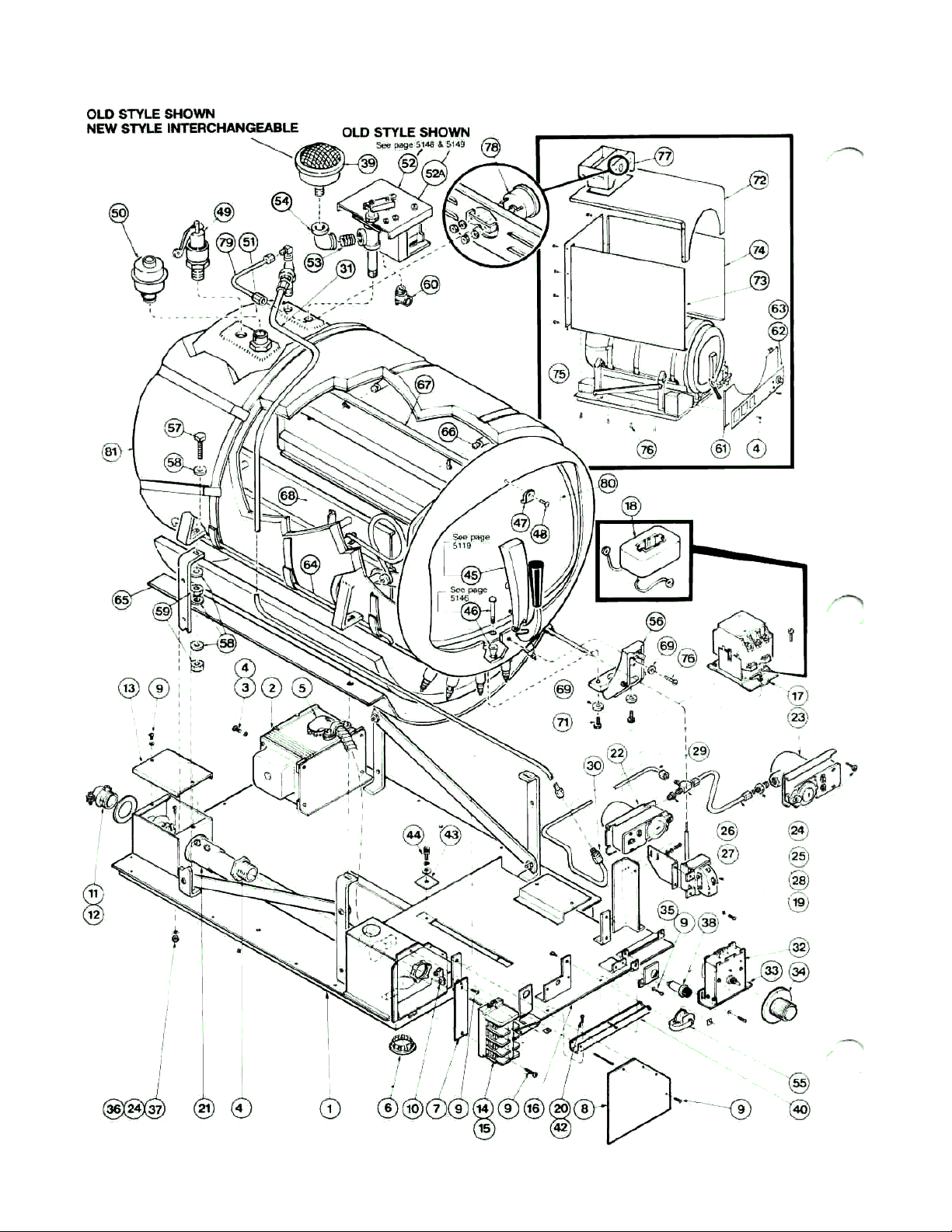
ST-E STEAM-IT STYLE C MASTER
ILLUSTRATION PARTS LIST
Item No. Description Part No.
1 Baseplate Ass'y —Fixed 95-3301
2 Transformer (440/480 V Units 10-5234
3 No 10 Lockwasher (stainless steel) *
4 No 10-32 x 1/2" Binding Hd Screw (st'n st'l) *
5 Lead Ass'y, Transformer 95-3394
6 Plug Button 10-3095
7 Plate-Term Strip Support 95-3289
8 Cover-Term Box 95-3484
9 No 8-32 x 3/8" Rd Hd Screw (st'n st'l) *
10 Ground Lug 10-6969
11 Connector 95-3500
12 Reducing Washer 10-6967
13 Junction Box Cover 95-3489
14 Terminal Strip Section 10-6962
15 Term Strip, End Section 10-6963
16 Baseplate sub-Ass'y —Movable 95-3302
17 Contactor-208V, 50/60 Cycle, Complete 10-5466
Contactor-230/240V, 50/60 Cycle, Complete 10-5467
18 Coil-208V, 50/60 Cycle 10-5470
Coil-230V, 50/60 Cycle 10-5471
19 Low Water Cut-Off 10-5990
20 No 6-32 x 1/4" Truss Hd Screw (st'n st'l) *
21 Connector 10-6966
22 Pressure Control-Open on Rise 95-0998
23 Pressure Control-Closed on Rise 95-0999
24 No 10-32x 1/2";Rd Screw (st'n st'l) *
25 Adapter-Straight 1/4 O.D -1/4 I P.S.M 10-2904
26 Adapter-Tee 1/8 I.P.S-1/4 O.D-1/4 0.D.M 10-3426
27 Reducing Bushing 1/4-1/8 I P S 10-3652
28 Tube 95-3305
29 Tube-Pressure Control 95-3304
30 Union-Compr Fitting 1/4 O.D 10-1154
31 Tubing-Steam Press Line 95-3387
32 Timer, 60-Minute 95-3404
33 Bracket, Timer 95-3277
34 Knob Dial 10-6307
35 Bracket-Pilot Light 95-3403
36 Lock Washer 10-2509
37 Hex Nut 10-32 10-2340
38 Pilot Light 10-6669
39 Exhaust Silencer 10-4963
40 Cage, Electric Wires 95-0483
41 Conduit-Nipple 10-6964
42 Speednut, #6-32 10-4110
43 Washer 95-0463
44 No 10-32 x 3/8 Hex Socket Hd Cap Screw (st'n
st'l) *
45 Door Handle Ass'y Complete 95-0144
46 Drain Plug Ass'y Complete 95-0154
Item No. Description Part No.
47 Handle Bumper 10-0226
48 No 8-32 x 3/8 Binding Hd Screw Ty "Z" (st'n st'l) *
49 Safety Valve 10-4636
50 Steam Trap 10-6156
51 Adapter 10-6158
52 Old Style Exhaust Valve *
Exhaust Valve-208V, 60 Cycle, Complete 95-0944
Exhaust Valve-230-480V, 60 Cycle, Complete 95-0945
Exhaust Valve-230V, 50 Cycle, Complete 95-0946
Exhaust Valve-208 & 230V, 50 Cycle 95-0946
52A New Style Exhaust Valve (Not Shown)
Exhaust Valve-220/240V, 50/60 Hz 09-6545
Exhaust Valve-208V, 50/60 Hz 09-6536
53 Nipple, 3/8 IPS 10-3852
54 Elbow 3/8 I P S st'd 90° 10-3851
55 Buzzer (Complete) 10-6665
56 Fulcrum & Drain Ass'y 95-0115
57 5/16-18 x 11/2" sq Hd Screw (st'l Cad PI) *
58 5/16 Flat Washer, 3/8 I D x #16 Ga St'd (st'l Cad PI) *
59 Hex Nut, 5/16-18 (st'l Cad PI) *
60 Connector, 3/8-90° 10-5036
61 Front Lower Panel Ass'y 95-3 388
62 Nameplate Panel (60 Cycle) 10-6595
63 Nameplate Panel (50 Ccyle) 10-7096
64 Rod 95-0466
65 Pan-Insulation 95-0465
66 Stud 10-1937
67 Pan Rack Ass'y-Right Side 95-2545
68 Pan Rack Ass'y -Left Side 95-2546
69 1/4 Shakeproof Int Tooth Lockwasher (st'n st'l) *
70 1/4-20 x 3/4" Rd Hd Screw (st'n st'l) *
71 1/4-20 x 78" Hex Hd Screw (st'n st'l) *
72 Case-Top Front Upper 95-3131
73 Case-Left Side 95-3140
74 Case-Right Side 95-3141
75 Case-Back 95-3490
76 No 8 x 3/8" Phil Truss Hd Screw Ty "A" (st'l, Ni PI) *
77 Flue Ass'y 95-3135
78 Pressure Gauge 10-0883
79 Tubing-Press Gauge 95-3270
80 Door Assembly, Complete 95-0124
81 Body Assembly (208V and 236V) 95-0478
Body Assembly (470V) 95-0479
*These parts are available at local hardware, plumbing and electrical outlets If not obtainable, special prices will be quoted by Market Forge
on request
Page 5

THE BUZZER
THE DOOR GASKET
The function of the Buzzer is to signify to the operator that the
cycle of cooking has been terminated
The Buzzer is mounted on a bracket which is positioned at the
front of the unit just under the front removable panel.
HOW THE BUZZER WORKS
The Buzzer electrical circuit is controlled by the timer When
the timer reaches "ZERO" (at the end of the cooking cycle),
the circuit will be completed and the Buzzer will continue to
sound until the timer knob is turned to the "OFF" position
THE COOKER DOOR ASSEMBLY
The door of the Cooker has been engineered to establish a
positive method of sealing the steam pressure within the
cooking cylinder As steam pressure builds up within the
cylinder, the door seal will tend to become more positive
However, the door should be adjusted to make a good initial
seal between the door gasket and the door opening without
the added assistance of internal cylinder steam pressures.
With the simple action of securing the door handle down in a
locked position, the door gasket should be sufficiently
compressed against the door opening, all the way around, to
prevent any steam leakage from occurring.
Keep the gasket clean. With normal closing and locking of
the door assembly, a steam-tight seal should be made
between the door gasket and the door opening. This seal
cannot be maintained if particles of foreign matter are
allowed to accumulate upon either of the contacting
surfaces
If leakage should occur by the door gasket before the
additional pressure of a steam build up within the cooking
chamber causes it to stop, the door assembly must be
regarded as improperly adjusted and a readjustment must
be made of the adjustment screw.
To change the door gasket, remove the entire door
assembly as a unit, remove and discard the old gasket,
replace it with a new one (no cement is required), and
reinstall the door assembly. Make an operational check
for leakage and adjust the door if necessary.
DOOR ASSEMBLY - Parts List
Item Description Part No.
1 Pivot Spring Bearing .....……….... 10-6765
2 Door Lift Springs (pair) . ..………... 10-2785
3 10 - 32 Machine Screw 1/2" long …10 1776
4 Door Gasket ....... ..………………. . 10-2666
5 Door & Door Spring Assy. .………. 95-3204
6 Door Spring ...... ……………… . 95-0127
— Complete Door Assembly
(Items 1 thru 6) .....………. 95-0124
5136
Page 6
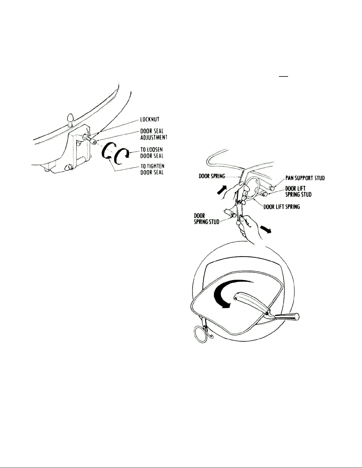
DOOR ADJUSTMENT
The door adjustment is located in the fulcrum casting at the base
of the door opening. This adjustment employes the use of a
screw and locknut. To adjust the Cooker door to a tighter closed
position (to prevent steam from leaking by the door gasket as
pressure builds up), it is necessary to loosen the locknut and
back off the screw at least one-quarter of a turn and retighten the
locknut.
5. To replace the door assembly, reverse the step by step
procedure described above.
DOOR LIFT SPRING REPLACEMENTS
Market Forge Company supplies replacement Door Lift
Springs in sets only. This policy has been found to be in the
best interest of the customer. Through continuous use, some
of the original qualities of the springs are lost and it becomes
advantageous to make replacements to both the left and right
Door Lift Springs in the event one becomes damaged or
broken.
Replacement Door Lift Springs are marked with tabs at the
factory prior to shipping to identify a right from a left spring.
These must be installed with the right Door Lift Spring on the
right and the left Door Lift Spring on the left of the door as
viewed from the front of the Cooker.
TO REMOVE THE DOOR ASSEMBLY
The Door Assembly can be removed from the inner cooking
chamber as a unit without the use of any special tools or
equipment. However, a systematic approach to this is warranted
as the clearances through the portal are close and much
confusion can result if not removed in the sequence described
below.
1. First, lift off and remove the two pan supports to expose the
door linkages on either side of the inner cooking chamber.
2. Raise the door to a fully opened position and disengage the
door spring from each of the door spring studs. Accomplish
this by counter-acting the force of the door lift spring with one
hand while working the end of the door spring of the door
assembly.
3. When the ends of the door spring have been completely freed
from their respective door spring studs, the door lift springs on
either side of the door assembly can easily be slipped off their
studs.
4. Rotate the entire door assembly out through the door opening,
passing the door handle through the opening first, and then
one end of the door spring as shown in the illustration The
remainder of the door assembly will then pass through the
door opening quite easily.
5067
Page 7
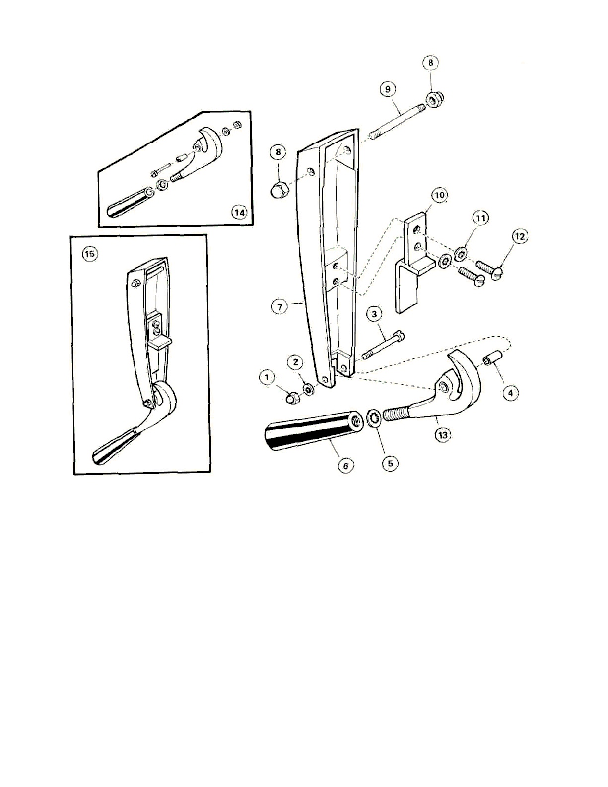
DOOR HANDLE ASSEMBLY - PARTS LIST
2 #10
Shakeproof Lockwasher
. . . 10-2514
4 Bearing Spacer
..............
95-
0120 5 3/8"
Shakeproof Lockwasher
. . 10-2517 6 Door Lock Knob
............
10-
0050
7 Door Handle Casting
.........
95-
0134
8 1/4" - 20
Acorn Nut
.........
10-
2359
*0btain
at local hardware store
11 1/4"
Shakeproof Lockwasher
.. 10-2513 12 1/4"- 20 x 5/8"
Rd. Hd. Screw
... 10-1731*
13
Door Lock Ass'y.
.....
.........
95-
3223
Door Lock Knob Ass'y.
(Items
1
thru
13) .........
Item Description Part No.
1 No. 10 - 32 Acorn Nut...... 10-2318
3 Locking Screw .............. 10-1999
Item Description Part No.
10 Door Handle Bearing Bracket ...... 95-0659
14
95-0145
9 Door Handle Bearing Stud .... 95-0658
15 Complete Door Handle Ass'y.
5119
95-0144
Page 8

FULCRUM & DRAIN ASSEMBLY
The Fulcrum and Drain Assembly is located at the lower
front of the cooking cylinder and furnishes a sturdy
anchorage for the door locking system of the door handle
Also provided in this assembly is a means of adjustment for
the door seal The drain port and drain plug provide a means
of discharging accumulations of water from the cooking
cylinder
ROLLER ASSEMBLY
Built Prior to 10/85 (Items 5, 6, 7, 8 & 9) Built after 10/85
(Items 2, 8, 9, 13 & 14) The Roller Assembly mu st be kept
free-rolling at all times Should this assembly be allowed to
become frozen due to lack of lubrication, undue strain will be
put on the door handle and the fulcrum casting while the
door is being locked Use only a dry lubricant such as
graphite, as oil or grease will tend to attract dirt to this area
5146
Page 9

SAFETY VALVE
D Old Style Shown
The Safety Valve is set to automatically relieve the cooking
compartment of excessive pressure build-ups by opening at a point
between 15 1/2 Ibs and 16 Ibs
CHECKING SAFETY VALVE
If the Safety Valve should leak continually with a pressure build-up,
or should it cause an interruption of the cooking cycle prematurely
(less than 15'/2 Ibs on the steam gauge), it must be determined to
be defective and be replaced However, the steam gauge should first
be checked for accuracy before making this determination The
steam gauge should register absolute zero with no pressure in the
cooking cylinder If the normal zero setting has advanced somewhat
through usage (a characteristic of steam gauges), the amount of
advancement from absolute zero must be subtracted from its
registered reading to determine the true steam pressure
THE FLUE
The Flue serves as a protection shield for the Steam Trap (B) Safety
Valve (A) Exhaust Valve (D) as well as a front-facing mount for the
Steam Gauge (E) As servicing of these parts may at times require
the removal of the flue, an exploded view drawing is provided to
show their proper relative positions within the flue and the method of
their assembly to the cooking cylinder
TO REMOVE THE FLUE
1 Unscrew and remove the exhaust silencer (F)
2 Detach the 3/16" copper tube connector (C) from the Steam
Gauge (E) at the ferrule nearest the steam gauge Then, remove
the copper tube entirely by freeing it at the other ferrule
3 Apply inward pressure at either sides of the Flue at points (1) and
(2) with a screwdriver This will collapse the side walls slightly to
allow the small fluted sections of sheet metal to clear the edges
of the flue opening provided in the outer shell of the Steam-It
With the restrictions of the flutes removed, the Flue may then be
lifted up over the parts it houses
4 To replace the Flue reverse the above steps
STEAM GAUGE
Located at the top rear of the Steam-It and mounted into the
forward face of the flue for visibility, the Steam Gauge registers the
pressure within the Steam-It cooking chamber To replace this unit it
is necessary to disconnect the 3/16" copper tube connector and
remove the two nuts holding the gauge framework in place
STEAM TRAP
The Steam Trap is located within the flue at the top rear of the
Steam -It It has the very important automatic, dual function of
exhausting all cold air from the cooking compartment and of making
a suitable seal to allow a pressure build-up of live steam during the
cooking cycle Failure of this unit to operate properly will result in
uneven cooking
HOW IT WORKS
With the introduction of steam into the cooking compartment, the
cold air escapes through the Steam Trap When sufficient generated
steam dispalces the cold air it passes through the Steam Trap and
the thermostatic element becomes heated and expands to ' make a
seal against the seat This action encloses the live steam within the
cooking compartment and allows a steam pressure build-up to
occur
TROUBLE TESTS AND REMEDIES
the first indication of defective Steam Trap operation will usually be
evidenced by uneven cooking If working properly, the steam
temperature will be even and cooking will be uniform through the
cooking compartment Trouble may occur either through premature
closing of the Steam Trap before all the cold air has been
exhausted or by its failure to close sufficiently to enable a proper
steam pressure build-up Either case warrants the replacement of
the Steam Trap
5147
Page 10

ST-E EXHAUST VALVE-Parts List
Page 11

5149
Page 12

CLEANING EXHAUST SILENCER
The Exhaust Silencer should be removed and cleaned periodically
As the cooking chamber is exhausted of steam through the silencer,
impurities can build up from food particles Cleanings should be
frequent enough to prevent clogging to occur For this reason, the
Exhaust Silencer is made easily accessible and simple to remove To
Clean
1 Remove the one-piece Exhaust Silencer from the unit by
unscrewing it in a counter-clockwise direction
2 Clean the Silencer by sloshing it in hot soapy water and rinse it in
clear water If dirt has clogged the Silencer, presoak it in an
alkaline cleaning solution
3 After cleaning stand the silencer on edge to allow it to drain
4 Screw it back into the elbow of the Exhaust Valve (Clockwise)
LOW WATER CUT-OFF
the Low Water Cut-Off is mounted above the timer assembly under
the front lower panel with its thermostat bulb extending and inserting
into a channel provided for it at the outer edge of the cast-in heating
elements It functions as a safety feature to shut off the complete unit
in event the water runs dry
HOW IT WORKS
If the Steam-It operated with no water or the water has evaporated
away, the temperature of the cooking cylinder will rise and by heat
induction effect the thermostat bulb of the Low Water Cut-Off
Electric current flow will be broken at the Low Water Cut-Off and the
unit will shut down With the replacement of water into the cooking
cylinder, the thermostat bulb will be cooled and the unit will then
again be operative after the reset button has been pressed If the unit
does not start after pressing the reset button, more time will have to
be allowed for further cooling
NOTE:
Should a cooking cycle be started with insufficient water, and
interrupted due to safety action of the Low Water Cut-Off, the food in
the process of cooking will be affected Proper compensation will
have to be made for the cooking performed and, with proper amount
of water in the cooking cylinder, a new cycle determined and set to
complete the process
TIMER
The Timer, located at the lower right front of the Steam-It, provides a
means of manual control The Steam-It is put into an automatic cycle
of cooking with the setting of the Timer to any of its calibrated
periods of cooking Its timing cycle, however, is automatically
delayed by the Timer Control Switch until free-venting has occurred
and a cylinder pressure build-up to 10 PSI has been reached
TROUBLE TESTS AND REMEDIES
If the Timer should fail to operate the Steam-It and a check shows
all wiring to be in good order, and should the Timer Control Switch
be found in good order as ascertained by a continuity check, the
Timer must be regarded as defective and must be replaced The
Timer is replaceable only as a complete unit
TIMER CONTROL SWITCH
The Timer Control Switch, located under the removable front lower
panel Just right of center, automatically delays the timer count-down
at the beginning of the cycle until the Steam-It has fully free-vented
out all cold air from within the cooking cylinder and pressure has
reached 10 PSI This delay insures the timer to count only that
portion of the cycle when cylinder steam pressure is actually acting
on the foods This, of course, is important when processing foods
which only require very short periods of cooking time
HOW IT WORKS
The copper tube which extends from the top of the cylinder to the
rear portion of the Timer Control Switch constantly reflects internal
cylinder steam pressures upon the Timer Control Switch's built-in
bellows While cylinder free-venting is occurring, the switch keeps
the timer circuit open After free-venting has terminated and when
the cylinder pressure has built-up to approximately 10 PSI, the
contacts will be forced closed by back-pressures working on the
bellows, the timer circuit will be completed, and the timer will then
start its countdown
DIAL ADJUSTMENTS (Refer to Fig 11) The cut-in point of the
Timer Control Switch has been factory set at its maximum setting of
10 Ibs and should not be altered unless it is found that the timer
does not start until well after 10 Ibs of steam pressure has been
realized on the pressure gauge In this case, insert a screwdriver into
the center slot (H) of the larger dial (G) and rotate slightly counterclockwise to adjust timer to start at 10 PSI
RECALIBRATING TIMER CONTROL SWITCH
Should the Timer Control Switch vary through usage from its original
factory setting, it may be restored to proper working order by
recalibration
A visual check of the Timer Control Switch during a trial cycle will
quickly determine the need of recalibration With the Timer Control
Switch dial set at 10 Ibs (fully clockwise), the timer motor should cutin when 10 Ibs of steam pressure is registered on the steam
pressure gauge By watching the smaller dial (F) of the timer Control
Switch, the cut-in of the switch may be observed and heard to click
forward at the moment the circuit is made to the timer motor At that
precise moment the pressure gauge should measure 10 Ibs
RECALIBRATION PROCEDURE
1 Set the larger dial (G) of the Timer Control Switch to 10 Ibs (fully
clockwise)
2 Loosen the two screws (I) and (J) located on either side of the dial
slot (H)
3 First, note the position of the slot (H) in relation to the dial (G)
Then, while holding the dial stationary, insert a screwdriver into
the slot and rotate slightly to adjust (Clockwise rotation will set the
Timer Control Switch to cut the timer in at an increased amount of
steam pressure-counterclockwise will allow it to cut-in at a
decreased amount of steam pressure) Tighten the two screws (I)
and (J) to hold this adjustment
4 Check the unit through a trial cycle and note the pressure gauge
reading when the Timer Control Switch is observed and heard to
click forward Pressure reading should then be at 10 Ibs (Check
also may be made by continuity) Re-adjust necessary
5152
Page 13

ELEMENT CONTROL SWITCH TIMER CONTROL SWITCH
ELEMENT CONTROL SWITCH
The Element Control Switch, located under the removable front
lower panel, just left of center, governs the flow of current to the
heating elements to maintain cylinder pressures at a near—constant
14 PSI
HOW IT WORKS
A copper tube extending from the top of the cylinder to the rear
portion of the Element Control Switch constantly reflects internal
cylinder steam pressures upon the built-in bellows of the Element
Control Switch to cause it to open or close an electrical circuit to the
contactor coil With little or no pressure applied to the bellows, the
circuit to the contactor will be closed, and providing the timer is set
to cycle, the contactor will click in and current will flow to the heating
elements When the pressure rises to 14 PSI (ongional factory
setting), the bellows will be sufficiently compressed by the steam
back-pressure to break the circuit to the contactor coil, the contactor
will click out, and current flow to the heating elements will cease
When cooling allows the pressure to drop below 13 Ibs, the bellows
will again complete the contactor coil circuit, activate the contactor to
click in, and allow the heating elements to energize Thus, by
working intermittently to open and close the contactor coil circuit, the
Element Control Switch, in effect, regulates current flow to the
heating elements
DIAL ADJUSTMENT
Two dial settings determine the operational range of the Element
Control Switch The larger dial (D) determines the maximum build-up
of cylinder steam pressure while the smaller dial (E) governs the
range of differential between the switch's cut-in and cut-off points
Should a lower cylinder cooking pressure be desired, adjust the
larger dial (D) by inserting a screwdriver into the slot (B) found at its
center and turning it slightly counterclockwise to lower the pressure
Clockwise rotation will increase the pressure. Pressure must not be
adjusted to exceed 14 Ibs as the safety valve is set to automatically
open just above this point
The cut-in and cut-off points of the Element Control Switch may be
adjusted by rotating the small screw at the center of the smaller dial
(E) Normal factory setting is for a one pound differential between
cut-in and cut-off To increase the range of differential, rotate screw
clockwise, to decrease the range of differential, rotate the screw
counterclockwise Check adjustments through a trial cycle by
observing pressure gauge reading when contactor clicks out at
maximum cylinder pressure and again when it clicks in after cylinder
cooling The difference in pressures as read on the pressure gauge
should, at these points, be approximately one pound
RECALIBRATING ELEMENT CONTROL SWITCH
The Element Control Switch may be recalibrated should it vary
somewhat, through usage from its original factory setting
At the precise moment of contactor "click-out", the dial setting of the
Element Control Switch and the steam pressure gauge reading
should both be 14 Ibs A slight override of steam pressure build-up
will normally occur and indicate itself on the pressure gauge after
the contactor has "clicked-out" This is normal and is not to be
interpreted as an Element Control Switch out of calibration
PRESSURE CONTROL SWITCH (BARKSDALE)
Models built after September 1980 use 2 Barksdale Pressure
Switches in place of the White-Rodgers Element Control
Switch and the Timer Control Switch
OPERATING PRESSURE ADJUSTMENT (BARKSDALE)
The operating pressure is determined by setting the right
switch (A) at approximately 10 PSI and the left switch (B) at
approximately 14 PSI Both switches were set at the factory
These settings can be verified by looking through the slot (in
the Red Rectangle) and observing the alignment of the black
line inside with the white scales on either side of the slot
To readjust turn the white knurled knob in appropriate
direction to raise or lower pressure
WARNING Because power must be on to adjust pressure
switches, be sure to protect against electrical shock
Check adjustments through a trial cycle and observe
pressure readings on pressure gauge when switch (B) clicks
off at maximum cylinder pressure and when switch (A) clicks
on after cylinder cooling Making adjustments as needed
being careful not to let switch (B) pressure be set to exceed
14 Ibs Since the safety valve is set to automatically open just
above this point
RECALIBRATING PRESSURE CONTROL SWITCH
The actuation valve (differential) is factory set and cannot be
recalibrated
5153
Page 14

RECALIBRATION PROCEDURE
1 Set the larger dial (D) of the Element Control Switch at
14 Ibs. pressure (dial (D) fully clockwise).
2. Loosen the two small screws (A) and (C) located on
either side of the dial slot (B)
4 Check this new sotting by operating the Steam It
through a trial cycle and note the pressure gauge
reading at the precise moment when the contactor
"clicks out" This should be at 14 Ibs. (Check may also
be made by continuity) Repeat the process of
adjustment until the Steam It test operates to
satisfaction
3. First, note the position of the slot (B) in
relation to the dial (D). Then, while holding the dial
stationary, insert a screwdriver in the slot to adjust.
(Clockwise to increase steam pressure —
counterclockwise to decrease pressure). Tighten
screws to hold this adjustment.
OPTIONAL STEAM-IT STAND
Market Forge Steam-Its can be supplemented with an optional stand
for utility where maximum compact ness is desired. The sturdy
stainless steel stand unit is equipped with adjustable leg extensions
which allow the unit to be installed and leveled over existing contours
in the floor.
The open under-shelf of the stand gives added utility, providing a
handy tabouret for cooking utensils- The open design lends itself to
maximum sanitary conditions because of the ease in which periodic
cleanings can be made.
Though simple in design and appearance, the Steam-It Stand is the
ideal arrangement for mounting in that it elevates the unit to the most
efficient working height, can be leveled easily, and may easily be
maintained in a state of cleanliness.
THE PILOT LIGHT
The Pilot Light is located at the lower right front of the
front panel. This unit is wired to operate when the heating
elements are on. The circuit will be broken when the timer
returns to the "ZERO" position. Thus, when the pilot light
is on and off it signifies that the heating elements are
cycling on and off to maintain cooking pressure in the
cooking chamber
5154
Page 15

ITEM NO. PART NO. DESCRIPTION
1
2
3
4
5
6
7
90-2657 Rear Panel St. Steel
Kit 90-3013 Rear Panel St. Steel Kit
90-2661 Side Panels R & L St. Steel
Kit 90-9039 Side Panels R & L St. Steel Kit
10-0631 Leg
90-8974 Ass'y. 24" x 33" Modular Frame
90-2993 Door Ass'y. L Hand St. Steel
Kit 90-9098 Door Ass'y. L Hand St. Steel Kit
90-3154 Door Ass'y. R Hand St. Steel
90-2663 Panel MTG Bracket
10-0493 Feature Strip
ITEM NO. PART NO. DESCRIPTION
8 90-3210 Bracket Magnetic Catch
9 10-5561 Magnetic Catch
10 10-1869 No. 10-32 x 1/2" Flat Head Screw
11 10-0454 Cabinet Hinge Right Bottom
10-0453 Cabinet Hinge Left Bottom
12 10-2365 Lock Nut
13 10-2511 Washer
14 10-2307 Hex Nut
5011A
Page 16

TROUBLE POSSIBLE CAUSE CORRECTION
Check timer for continuity of primary circuit thru
Unit releases pressure before cooking
Steam -It fails to operate at all. (No
pressure build-up).
TROUBLE SHOOTING GUIDE
1. Blown fuse.
2. Wiring is defective.
3. Not installed correctly.
4. Element control switch or contactor coil
not in circuit.
5. Current not passing through timer to
start unit.
1. Replace fuse. If it blows again, check that
source of electric supply is 60 Amp.
2. Check all wiring. Repair or replace.
3. Check wiring diagram for correct hookup.
4. Check both element control switch and
contactor coil for continuity. Repair or replace
either if found defective.
5.
timer control switch.
Steam -It operates but fails to build-up
to 14 Ibs. pressure
cycle has terminated on timer.
Timer does not function at 10 PSI of
cylinder pressure to start countdown.
Uneven cooking. 1. Steam trap closing prematurely-preventing
1. Steam trap fails to properly close.
2. Exhaust valve fails to hold pressure
at 14 Ibs.
3. Steam leaks around door.
4. Safety valve blows off below 15 Ibs.
pressure.
5. Element control switch not properly
adjusted.
1. Power loss.
2. Low water cut-off has functioned
prematurely.
1. Loose or broken electrical leads to
the timer or timer control switch.
2. Timer motor defective.
3. Timer control switch defective or
out of adjustment.
removal of air from the cooking chamber.
1. Replace the steam trap.
2. Check for correct adjustment — or strip
down, clean and repair.
3. Clean seating surfaces and gasket to make
sure they are free of food particles. Check for
worn gasket, or make door adjustment.
4. Replace safety valve. 5. Readjust.
1. Check for disruption at source of electric
supply.
2. Adjust or replace low water cut-off.
1. Repair or replace defective wiring.
2. Check timer motor for continuity. Replace
complete timer if found defective.
3. Make continuity check, adjust, replace if
necessary.
1. Replace the steam trap.
Heating elements cutting out before
13 Ib. pressure is reached.
1. Pressure cutting off electric at the element
control switch too soon.
1. Make adjustments on the dial of the element
control switch to remedy.
5155
Page 17

5156
Page 18

UNITS BUILT PRIOR TO
6/79
Page 19

FOR 3 PHASE
-4 WIRE. CONNECTION:
380/22O OR 4l5/240V
CONNECT Ll L2 L3 TO THE. 3 lNCOMING PHASES
POWER
REQUIREMENTS
V
CONTROL CIRCUIT
CONNECT N TO THE INCOMING NEUTRAL
CONNECT E TO THE INCOMING EARTH (GROUND WIRE)
CONNECT CONTROL CIRCUIT WIRE C1 TO L3
CONNECT CONTROL CIRCUIT WIRE C2 TO N
FOR 3 PHASE -3 WIRE CONNECTION : (380V OR. 415V,')
CONNECT L1 L2 L3 TO THE 3 INCOMING PHASES
CONNECT E TO THE INCOMING EARTH (GROUND WIRE)
DO NOT CONNECT ANY INCOMING WIRES TO N
REMOVE CONTROL CIRCUIT WIRE C1 FROM L3
REMOVE- CONTROL CIRCUIT WIRE C2_ FROM N
CONNECT SEPARATE 22O/240 VOLT SUPPLY ONLY TO C1 C2
FOR SINGLE PHASE CONNECTION: (220V OR 240V)
BRIDGE L1 L2 L3 AND CONNECT TO INCOMING
PHASE CONNECT N TO INCOMING NEUTRAL
CONNECT CONTROL CIRCUIT WIRE C1 TO L3
CONNECT CONTROL CIRCUIT WIRE C2 TO N
NOTE: FOR. Norway
230 V, 3PH,, 5OHz., 3 WIRE
ELECTRICAL SERVICE USE
WIRING DIA B95-3775
NOMINAL AMPS. PER WIRE
3 PHASE 1 PHASE
380 V. 415
220 V. 240V.
16 17 48 51
12.0 KW 12.0 KW
MODEL ST-F For Operation On
380/415 Volt-3 Phase
Supply
OR
220/2401 VOLT- Single Phase Supply
50 50 Cycles
All Heating Elements Rated 236 Volts 1
Page 20

Page 21

 Loading...