

Page 1

TABLE OF CONTENTS
ST-AS STEAM COOKER
Subject Code No. Page
SEQUENCE OF OPERATION 5133 3
SUGGESTED STEAM CONNECTIONS 5133 3
BALL FLOAT TRAP 5134 4
ILLUSTRATION AND PARTS LIST 5135 5
DOOR ASSEMBLY AND GASKET 5136 6
DOOR ADJUSTMENT AND REMOVAL 5067 7
DOOR HANDLE ASSEMBLY 5119 8
FULCRUM & ROLLER ASSEMBLY 5120 9
FLUE, PRESSURE GAUGE & STEAM TRAP 5137 10
PILOT LIGHT & TIMER 5138 11
TROUBLE SHOOTING GUIDE 5139 12
WIRING DIAGRAM 5140 13
OPTIONAL STEAM-IT STAND 5141 14
24 INCH CABINET BASE 5142 15
WATTS PRESSURE REDUCING VALVE 5129 16
Page 2
HOW TO USE THIS MANUAL
This manual contains maintenance and service instructions for
the Automatic, Direct-Connected Steam-It, Style H Model ST-AS.
The exploded view drawings of components are aids to the
identification, disassembly and assembly of parts. The parts
listings provide information necessary for the ordering of
replacement parts (proper part names and part numbers). When
requesting parts or service, always furnish the model and serial
number of your unit. These numbers are located on the name
plate affixed to the top surface of the Steam-It.
STEP 5. The steam trap closes from the intense heat
generated by steam acting upon its thermostatic
element and free-venting will cease.
STEP 6. A full steam pressure build-up to approximately 14
P.S.I, will occur within the cooking chamber. The
Steam -It door must be kept locked until the cooking •
period has completely finished.
STEP 7. The timer will return to "zero" position and cooki ng
wilt be terminated. The inlet valve will close, the
exhaust valve will open, the buzzer will again sound,
and the pilot light will go out. The buzzer will continue
to sound until the timer is turned to the "off" position.
OPERATION SEQUENCE
STEP 1. Put the food in a proper pan for the cooking to be
performed and place it in the Steam-It in keeping
with proper loading techniques.
STEP 2. Close and lock the door into position by placing the
tongue of the door lock under the roller of the fulcrum
casting and press downward until the handle comes to
a firm stop. This lock makes the initial seal and when
steam pressure builds up within the cooking chamber
the door will be forced to a tighter closed position.
STEP 3. Turn the Steam-It on by setting the timer clock past
and then back to the desired cooking period. The pilot
light will go on to signify that cooking is in progress.
STEP 4. The steam exhaust valve will automatically close, the
steam inlet valve will open, and a period of freeventing through the open steam trap will occur. During
this period of free-venting, trapped cold air is
exhausted from the cooking chamber and replaced
with live steam.
STEAM REQUISITES
The ST-AS Steam-It is designed for operation with a piped-in
steam supply not in excess of 14 Ibs per square inch. Should it
be used with a system of steam generation that exceeds 14 Ibs
per square inch, a pressure regulator must be used on the
steam input line to reduce and regulate the steam pressures
within the operational range of the Steam-It.
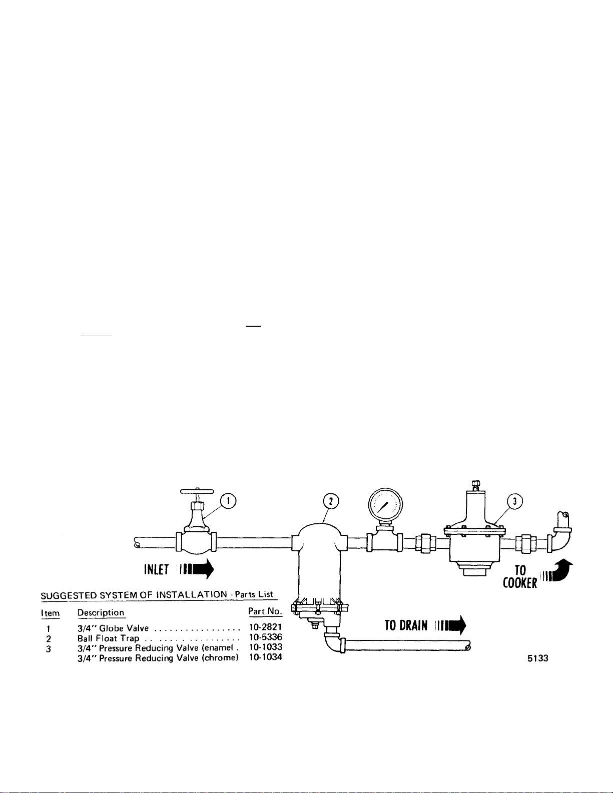
SUGGESTED STEAM CONNECTIONS
The illustration shows a recommended system of installation
which provides a regulating valve for delivery of 14 Ibs of steam
pressure, a globe valve for emergency shut off, a pressure
gauge to measure the pressure input from the source of supply,
and a ball-float trap to prevent dirt and water from entering the
unit. The globe valve, regulating valve, and ball-float trap and
pressure gauge are not furnished with this equipment. The
pres-gauge must be selected to operate within the range of the
pressures experienced at the place of installation. With the
introduction of a pressure reducing valve, the Steam-It will then
require input steam pressures in excess of 14 Ibs from its
source of supply.
NOTE: With pressure constant and between 11 and 14 PSI,
use the same system of installation with the pressure
reducing valve omitted.
Page 3
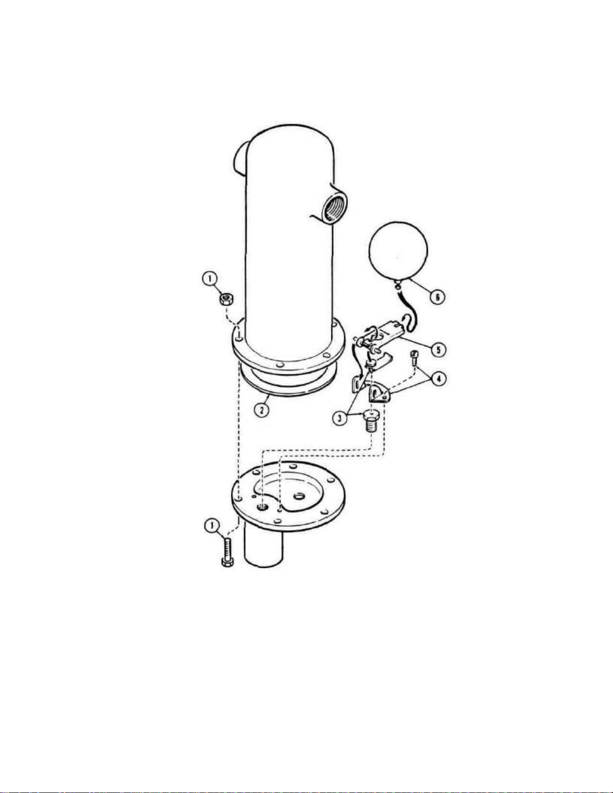
BALL FLOAT TRAP PART NUMBER 10-5336
2 Cover Gasket
10-5639
3 Valve and Sea
10-5640
4 Bracket and Screw
10-5642
5 Lever Assembly
10-5641
6 Ball Float
10-5643
PART NUMBER 10-5473, CHROME
Item Description Part No.
1 Cover Bolt and Nut 10-5644
5134
Page 4
Page 5

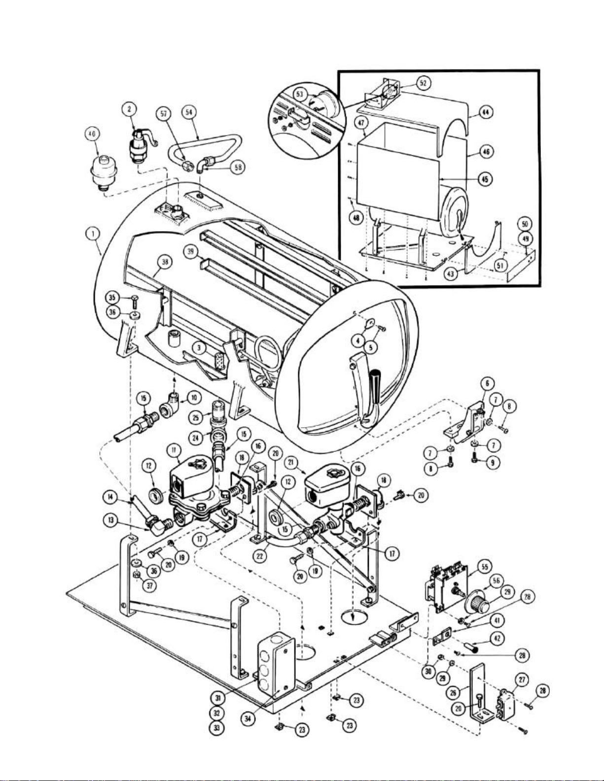
ST-AS STEAM-IT
2 Safety Valve
10-4636 3 Strainer Ass'y
95-0516 4 Handle Bumper
10-0226 5 No.
8 - 32 x 3/8"
Binding Hd. Screw
10-1774 6 Fulcrum
95-0116 7 1
/4" Sha
keproof Washer
10-2513 8 1/4" - 20 x 3/4"
Rd. Hd. Screw
10-1763 9 1/4" - 20 x 7/8"
Hex. Hd. Screw
10-1790 10 Street Elbow,
90° 10-2811 11 Solenoid Valve (Inlet)
10-5859 12 Grommet
10-0280 13 Elbow
1/2"
I.P.S. x
5/8 0.
D. 10-
2837
15 1/2"
I.P.S. x
5/8 0.
D. Straight Connector
10-2867 16 Nipple
1/2"
I.P.S. 10-
1107 17 Bracket
95-0065 18 Elbow
&
Bracket Ass'y.
95-
0064 19 1/4"
Lockwasher
10-2500 20 1/4" - 20 x 1/2
Hex. Hd. Screw
10-2073 21 Solenoid Valve (Outlet)
10-
5787 22
Tubing
95-3154 23 Nut, Grip
1/4" - 20 10-2312 24 Elbow
1/2"
I.P.S. St'd.
90° 10-2853 25 Nipple
1/2"
I.P.S. 10-
2864 26 Support Bracket, Buzzer
95-2007 27 Buzzer
10-4563 28 No.
8 - 32 x 3/8"
Rd. Hd. Screw
10-1717 29 No.8 Lockwasher
10-
2518 30
Hex. Nut,
#8-
32 10-2378 31 Handy Box
– Raco
10-
5163 32 Ground Lug
10-5492 33 No.
10 - 32 x 3/8"
Rd. Hd. Screw
10-1759 34 Cover, Handy Box
- Raco
10-5164 35 5/16"- 18
x 1"Hex. Hd. Screw
10-2105 36 5/16"
Flat Washer
10-2405 37 Hex. Nut
5/
16"- 18 10-2307 38 Pan Support
- Left Side
95-0097 39 Pan Support
- Right Side
95-
0096 40 Steam Trap
10-
6156 41 Bracket, Pilot Light
95-3408 42 Pilot Light
10-5052 43 Front Lower Panel Ass'y.
95-3185 44 Case -
Top Front Upper
95-3131 45 Case -
Left Side
95-3140 46 Case -
Right Side
95-
3141 47 Case -
Back
95-3126 48 No. 8 x
3/8"
Phil. Truss Hd. Screw Ty. "A"
10-1956 49 Nameplate Panel
(60
Cy.) 10-
6587 50 Decal, Dial Overlay
(50
Cy.) 10-
6577 51 No.
10 - 32 x 1/2"
Binding Hd. Screw
10-1776 52 Flue Ass'y.
95-3135 53 Pressure Gauge
10-5399 54 Tubing
- Press. Gauge
95-3285 55 Timer,
60
Minute
95-3393 56 Knob, Dial
10-
6381 57 Comp. Conn.,
1/8"
I.P.S. F'male x
3/16" 0.
D. 10-
3361
MASTER ILLUSTRATION PARTS LIST
Item Description Part No.
1 Body Assembly 95-2156
14 Tubing 95-2997
58 Comp. El. 900, 1/8" I.P.S. Male x 3/16" 0. D. 10-3360
Page 6

THE BUZZER
2 Door Lift Springs (pair)
10-2785
3
4
10 - 32
Machine Screw
1/2"
long
.
Door Gasket
101776
10-2666
5 Door & Door Spring Assy.
95-3204
6 Door Spring
95-0127
6)
The function of the Buzzer is to signify to the operator that the
cycle of cooking has been terminated.
The Buzzer is mounted on a bracket which is positioned at the
front of the unit just under the front removable panel.
THE DOOR GASKET
Keep the gasket clean. With normal closing and locking
of the door assembly, a steam-tight seal should be made
between the door gasket and the door opening. This seal
cannot be maintained if particles of foreign matter are
allowed to accumulate upon either of the contacting
surfaces.
HOW THE BUZZER WORKS
The Buzzer electrical circuit is controlled by the timer. When
the timer reaches "ZERO" (at the end of the cooking cycle),
the circuit will be completed and the Buzzer will continue to
sound until the timer knob is turned to the "OFF" position.
THE COOKER DOOR ASSEMBLY
The door of the Cooker has been engineered to establish a
positive method of sealing the steam pressure within the
cooking cylinder. As steam pressure builds up within the
cylinder, the door seal will tend to become more positive.
However, the door should be adjusted to make a good initial
seal between the door gasket and the door opening without
the added assistance of internal cylinder steam pressures.
With the simple action of securing the door handle down in a
locked position, the door gasket should be sufficiently
compressed against the door opening, all the way around, to
prevent any steam leakage from occurring.
DOOR ASSEMBLY - Parts List
Item Description Part No.
1 Pivot Spring Bearing 10-6765
If leakage should occur by the door gasket before the
additional pressure of a steam build up within the cooking
chamber causes it to stop, the door assembly must be
regarded as improperly adjusted and a readjustment
m ust be made of the adjustment screw.
To change the door gasket, remove the entire door
assembly as a unit, remove and discard the old gasket,
replace it with a new one (no cement is required), and
reinstall the door assembly. Make an operational check
for leakage and adjust the door if necessary.
Complete Door Assembly (Items 1 thru
95-0124
5136
Page 7

DOOR ADJUSTMENT
The door adjustment is located in the fulcrum casting at the
base of the door opening. This adjustment employs the use of
a screw and locknut. To adjust the Cooker door to a tighter
closed position (to prevent steam from leaking by the door
gasket as pressure builds up), it is necessary to loosen the
locknut and back off the screw at least one-quarter of a turn
and retighten the locknut.
5. To replace the door assembly, reverse the step by step
procedure described above.
DOOR LIFT SPRING REPLACEMENTS
Market Forge Company supplies replacement Door Lift
Springs in sets only. This policy has been found to be in the
best interest of the customer. Through continuous use, some
of the original qualities of the springs are lost and it becomes
advantageous to make replacements to both the left and right
Door Lift Springs in the event one becomes damaged or
broken.
Replacement Door Lift Springs are marked with tabs at the
factory prior to shipping to identify a right from a left spring.
These must be installed with the right Door Lift Spring on the
right and the left Door Lift Spring on the left of the door as
viewed from the front of the Cooker.
TO REMOVE THE DOOR ASSEMBLY
The Door Assembly can be removed from the inner cooking
chamber as a unit without the use of any special tools or
equipment. However, a systematic approach to this is warranted
as the clearances through the portal are close and much
confusion can result if not removed in the sequence described
below.
1. First, lift off and remove the two pan supports to expose the
door linkages on either side of the inner cooking chamber.
2. Raise the door to a fully opened position and disengage the
door spring from each of the door spring studs. Accomplish
this by counter-acting the force of the door lift spring with
one hand while working the end of the door spring of the
door assembly.
3. When the ends of the door spring have been completely
freed from their respective door spring studs, the door lift
springs on either side of the door assembly can easily be
slipped off their studs.
4. Rotate the entire door assembly out through the door
opening, passing the door handle through the opening first,
and then one end of the door spring as shown in the
illustration. The remainder of the door assembly will then pass
through the door opening quite easily.
5067
Page 8

1/4"
Shakeproof Lockwasher
Item Description Part No. Item Description Part No.
1 No. 10 - 32 Acorn Nut 10-2318 10 Door Handle Bearing Bracket 95-0659
2 # 10 Shakeproof Lockwasher 10-2514 11
3 Locking Screw 95-0563 12 1/4"-20 x 5/8" Rd. Hd. Screw 10-1731
4 Bearing Spacer 95-0120 13 Door Lock Ass'y. 95-3223
5 3/8" Shakeproof Lockwasher 10-2517
7 Door Handle Casting 95-0134 15 Complete Door Handle Ass'y.
8 1/4"- 20 Acorn Nut 10-2359
9 Door Handle Bearing Stud 95-0658
DOOR HANDLE ASSEMBLY - PARTS LIST
14 Door Lock Knob Ass'y. (Items 1
(Items 1 thru 13) 95.0144
10-2513
95-0145
Page 9

THE FULCRUM ASSEMBLY
Item Description
Part No.
7
Bron
ze Bearing
12
14 1/4-20x 5/8
Helicoil
10-3116
The Fulcrum Assembly is located at the lower front of the
cooking cylinder and furnishes a sturdy anchorage for the door
locking system of the door handle. Also provided in this
assembly is a means of adjustment for the door seal.
FULCRUM ASSEMBLY - Parts List
1 Fulcrum Casting 95-2176
2 1/4 -20x 3/8 Helicoil 10-3111
3 1 /4" Shakeproof Washer 10-2513
4 5 1/4-20 Cap Screw, 7/8" long
10-32 Hex Nut
6
# 10 Shakeproof Lockwasher
8 Bearing Spacer 95-0120
9
10 - 32 Machine Screw, 1 1/2"long
Roller Assembly (Items 5 thru 9)
10
1/4-20 Machine Screw, 3/4"long
11
1/4-20 Allen Set Screw
13 1/4-20 Famine Nut 10-2358
Complete Fulcrum Assy.
(Items 1-14 less item 2A)
10-1790
10-2339
10-2514
10-1578
95-0563
95-0149
10-1763
10-2087
95-2003
ROLLER ASSEMBLY CLEANING
The Roller Assembly provides a sturdy, free-rolling anchor
for the hooked arm of the door handle. Note that items 5, 6,
7, 8, and 9 in the illustration above makes up the complete
Roller Assembly, item 10.
The Roller Assembly must be kept free-rolling at all times.
Should this assembly become "frozen" due to
accumulations of dirt or food matter, strain will be put upon
the door handle and the fulcrum casting when the door is
being locked. Use only a dry lubricant such as graphite, as
oil or grease will tend to attract dirt to this area.
THE SAFETY VALVE
The Safety Valve is set to automatically relieve the cooking
compartment of excessive pressure buildups by opening at
a point between 151/2 Ibs. and 16 Ibs.
CHECKING THE SAFETY VALVE
If the Safety Valve should leak continually with a pressure buildup, or should it cause an interruption of the cooking cycle
prematurely (less than 151/2 Ibs. on the steam gauge), it must be
determined to be defective and be replaced. However, the steam
gauge should first be checked for accuracy before making this
determination. The steam gauge should register absolute zero
with no pressure in the cooking cylinder. If the normal zero setting
has advanced somewhat through usage (a characteristic of steam
gauges), the amount of advancement from absolute zero must be
subtracted from its registered reading to determine the true steam
pressure.
5120
Page 10

THE FLUE
B
1/2"
Steam Trap
..........
10-
6156 C Pressure Gauge Tubing
....... 10-3285
The Flue serves as a protective shield for the steam trap (B)
and the safety valve (A) as well as, a front facing mount for
the steam gauge (D). As servicing of these parts may at
times require the removal of the Flue, an exploded view
drawing is provided to show their proper relative positions
within the Flue and the method of their assembly to the
cooking cylinder.
TO REMOVE THE FLUE
1. Detach the 3/16" copper tube connector or (C) from the
steam gauge (D) at the ferrule nearest the steam gauge.
Then, remove the copper tube entirely by freeing it at the
other ferrule.
2. Apply inward pressure at either side of the Flue at points
(1) and (2) with a screwdriver. This will collapse the side
walls slightly to allow the small fluted sections of sheet
metal to clear the edges of the flue opening in the outer
shell of the Steam-It. With the restrictions of the flutes
removed, the Flue may then be lifted over the parts it
houses.
3. To replace the Flue, reverse steps above.
FLUE -Parts List
Item Description Part No.
A 1/2"- 15 Ib Safety Valve ...... 10-4636
D 0 - 30 Ib Pressure Gauge ..... 10-5399
THE STEAM PRESSURE GAUGE
Located at the top rear of the Steam-It and mounted into the
forward face of the flue for visibility, the Steam Pressure
Gauge registers the pressure within the Steam-It cooking
chamber. To replace this unit it is necessary to disconnect
the 3/16" copper tube connector and remove the two nuts
holding the gauge framework in place. Normal pressure
reading during a cycle of cooking will be:
1. Immediately after the Steam-It is set into operation; a
gradual rise to approximately 5 P.S.I.
2. After full free-venting has exhausted all cold air from
the cylinder; an increase in pressure to approximately
1 4 P.S.I.
3. During the remainder of the cooking period; a relatively
constant pressure reading of about 14 P.S.I.
4. After the timer has returned to the "ZERO" position and
complete exhaust venting has occurred; a pressure
reading of zero.
THE STEAM TRAP
The Steam Trap is located within the flue at the top rear of
the Steam-It. It has the very important automatic, dual
function of exhausting all cold air from the cooking
compartment and of making a suitable seal to allow a
pressure build-up of live steam during the cooking cycle.
Failure of this unit to operate properly will result in uneven
cooking.
HOW IT WORKS
With the introduction of steam into the cooking
compartment, the cold air escapes through the Steam
Trap. When sufficient generated steam displaces the cold
air, it passes through the Steam Trap, and the thermostatic
element becomes heated and expands to "make" a seal
against the seal against the seat. This action encloses the
live steam within the cooking compartment and allows a
steam pressure build-up to occur.
5137
Page 11

TROUBLE SHOOTING
THE TIMER
The first indication of defective Steam Trap
operation will usually be evidenced by uneven
cooking. If working properly, the steam temperature will be even and cooking will be uniform
through the cooking compartment. Trouble may
occur either through premature closing of the
Steam Trap before all the cold air has been
exhausted or by its failure to close sufficiently to
enable a proper steam pressure build-up. Either
case warrants the replacement of the Steam
Trap.
NOTE: The Steam Trap cannot exhaust cold air
properly if the thermostatic element is already
heated to its closed position prior to the start of a
new cycle. Therefore, a short interval is
recommended between cook ing cycles to allow it
to sufficiently cool. Usually the normal unloading
and reloading time is sufficient.
THE PILOT LIGHT
The Pilot Light is located at the lower right front of
the front panel. This unit is wired to operate only
when the timer is set to a cooking cycle. The
circuit will be broken when the timer returns to the
"ZERO" position. Thus, when lit, it signifies that
the Steam-It is in the act of cooking.
The Timer, located at the lower right front of the
Steam-It, provides a means of manual control. The
Steam-It is put into an automatic cycle of cooking with
the setting of the Timer to any of its calibrated periods
of cooking.
TROUBLE SHOOTING
If setting the Timer fails to operate the Steam-It and
the pilot light also fails to light, look first for a break in
the electric supply line (main switch off, burned out
fuse, defective wiring, etc.). Then look for poor
connections or defective wiring within the Steam-It
itself. With these initial checks accomplished
satisfactorily and the unit still inoperative:
1. If the pilot light comes on but timer fails to operate
then check terminals 11 and 12 to see if 115V is
present. If not, replace the timer.
2. Apply 115 volts across the solenoid coil terminals
of the steam inlet valve and the steam exhaust valve,
in turn, to determine if their solenoids or valves are in
proper working order.
The Timer is replaceable only as a complete unit as
factory repairs of it are not practical in the economic
interest of the customer
Page 12

TROUBLE POSSIBLE CAUSE CORRECTION
TROUBLE SHOOTING GUIDE
Setting the timer tails to light the pilot light. 1. Power not reaching unit.
2. Pilot light burned out; connections loose;
defective wiring.
3. Timer circuit not completed; loose
connections; defective wiring; defective
timer.
Steam fails to enter cooking chamber. 1. Operating circuit broken; inlet valve defective; timer
defective.
Steam-It fails to build up to approx. 14 Ibs pressure. 1. Induced steam to unit has in-
sufficient pressure.
2. Steam leaks around door.
3. Steam trap fails to properly close.
4. Safety valve blows off below 14 Ibs
pressure.
5. Exhaust valve fails to close.
1. Check for interruption in your
electrical input line.
2. Replace pilot light assembly; tighten
connections; replace defective
wiring.
3. Check connections; replace defective
wiring; If pilot light lights and unit is
inoperative -check for defective
timer. Replace if defective.
1. Check for faulty connections or defective
wiring - tighten or replace. Make continuity
check of solenoid coil. Replace any defective
components. If okay -replace timer.
1. Provide suitable pressurized steam to
unit.
2. Check for worn gasket. Adjust door or
replace gasket.
3. Replace the steam trap. 4.
Replace safety valve.
5. Check ex haust valve solenoid coil
continuity. Check for binding valve.
Replace defective components.
Steam-It does not shut down when timer reaches
zero.
Uneven cooking. 1. Steam trap closing prematurely. 1. Replace the steam trap.
Buzzer fails to stop buzzing when timer dial reaches
"O".
1. If unit fails to exhaust all steam: Circuit to
exhaust valve solenoid is broken or exhaust
valve is binding in a closed position.
2. If neither the exhaust valve or the inlet
valve operates to shut -down position, timer
is defective.
3. Check to see if cirucit to inlet valve
solenoid is broken or inlet valve is
binding in an open position.
1. Short. 1. Check connections or replace wire where
1. Make continuity checks of ex haust valve
solenoid coil. Re-establish circuit if
found broken. Repair or replace valve if
found binding.
2. Replace timer.
3. Make continuity checks to inlet valve
solenoid coil. Reestablish circuit if
found broken. Repair or replace valve if
found binding.
needed.
Page 13

Page 14

OPTIONAL STEAM-IT STAND
1
Corner Bracket with set screw
. .
27"
Leg
... ................
Leg Top
... ................
Flat Washer
1/16"
th'k
...... .
Cap Bracket
............. .
Complete Stand Ass'y
...... .
Market Forge Steam-Its can be supplemented with an optional stand for
utility where maximum compactness is desired. The-sturdy stainless steel
stand unit is equipped with adjustable leg extensions which allow the unit
to be installed and leveled over existing contours in the floor.
The open under-shelf of the stand gives added utility, providing a handy
tabouret for cooking utensils. The open design lends itself to maximum
sanitary conditions because of the ease in which periodic cleanings can be
made.
Though simple in design and appearance, the Steam-It Stand is the ideal
arrangement for mounting in that it elevates the unit to the most efficient
working height, can be leveled easily, and may easily be maintained in a
state of cleanliness.
STEAM-IT STAND ASSEMBLY - Parts List
Item Description Part No.
Shelf ......................
2
3
4
Rd. Hd. Screw 1/4" - 20 x 5/8" .
5
6
Lockwasher1/4" .......... .
7
8
9
95-1680
25-1507
10-0634
10-0635
10-1804
10-2520
10-2400
95-3211
95-0300
Page 15

24 INCH CABINET BASE - Parts List
90-3020 Rear Panel Enamel
9 10-
5561 Magnetic Catch
909039
Side Panels R & L St. Steel
10 90-9057 Door Handle
2 90-9041 Side Panels R & L Enamel
11 10-
2422 Special Washer
3 10-
0631 Leg 12 10-1869 No. 10
-
32 x 1/2" Flat Head Screw
4 90-
8974 Ass'y. 24" x 33" Modular Frame
13 10-
0454 Cabinet Hinge Right Bottom
90-
9098 DoorAss'y. St. Steel
14 90-
3185 Double Washer
5 90-9099 Door Ass'y
-
Enamel
15 10-
2511 Washer
6 90-
2663 Panel MTG Bracket
16 10-
2147 Hex. Nut
10-
0493 Feature Strip
17 10-
1982 Self Tapping Screw
7 18 10-2514 #
10 Lockwasher
ITEM NO. PART NO. DESCRIPTION ITEM NO. PART NO. DESCRIPTION
90-3013 Rear Panel St. Steel 8 90-3210 Bracket — Magnetic Catch 1
5142
Page 16

WATTS PRESSURE REDUCING VALVE
OPERATION OF WATTS 3/4 REDUCING VALVE
Steam enters the valve at the inlet port and passes upward
through the seat (8) into the discharge side
of the valve. As pressure in the discharge side increases, it forces
the diaphragm (2) upward, overcoming the tension of the adjusting
spring (1) and closing valve. As the pressure drops, the adjusting
spring forces the dia phragm down, reopening the valve. Where
demand and initial pressures are fairly constant, the valve opens to
the proper position and maintains the desired reduced pressure.
ADJUSTING WATTS 3/4 REDUCING VALVE
1. Release the adjusting screw lock nut and loosen the adjusting
screw enough to release all tension on adjusting spring (1).
2. Turn steam on slowly. Then turn adjusting screw clockwise just
enough to allow the valve to open slightly. Allow cooker to
operate in this manor several minutes.
3 Turn adjusting screw down slowly, at intervals, until reduced
pressure reaches the desired Point. (5 P.S.I.)
ITEM 1 PART NO. 10
1083
2 10 1082 Diaphragm
3 10 1075 Diaphragm Gasket
4 10-1076 Diaphragm Button Stem Assy.
5 10 1077 Strainer
6 10-1078 Bottom Plug
7 10 1079 Bottom Spring
8 10-1080 Seat
9 10-1081 Disc Assy.
10 10-1033 3/4" Complete valve-Enameled
10-1034 3/4" Complete valve-Chrome
WATTS PRESSURE REDUCING VALVE - % INCH
To provide adequate steam pressure regulation
steam cookers are equipped with a steam pressure
reducing valve. The 3/4" Watts pressure reducing valve is
designed to operate from a 7 to 50 P.S.I, source of steam
pressure and reduce this to 5 P.S.I, for delivery to your cooker.
Installation must be made from your source of steam supply,
through the pressure reducing valve, and into the manifold input
port of the steam cooker.
WARNING: Before final connection is made, blow down
your steam line to remove all dirt, scale, packing and
compound which may have accumulated during the
installation of piping to the cooker.
DESCRIPTION Adjusting Spring
4. Tighten adjusting screw lock nut.
5. If chattering noise should occur turn adjusting screw located in
bottom half of valve body, clockwise or counterclockwise,
until chattering stops.
INSPECTION - MAINTENANCE - REPAIRS
Reports of unsatisfactory regulation of the pressure reducing valve
is usually due to dirt, pipe compound, etc., blocking the internal
strainer, or gumming up the seat and disc assembly. To clean the
strainer, seat, and disc assembly remove the bottom plug (6) and
remove strainer screen (5), bottom spring (7) and disc assy. (9)
Clean the lower part of the valve. This can be accomplished
without removing the valve from the line or unbolting the cover. If
cleaning the strainer and disc assy. does not correct fault, the disc
assy. and seat should be replaced. Also the top cover should be
removed and the diaphragm button stem assembly should be
removed and cleaned.
5129
 Loading...