

Market Forge ST-AG Installation Manual

OWNER’S MANUAL
STEAM-IT
Gas Operated Pressure Cooker
STYLE F
MODEL: □ ST-AG
35 Garvey Street, Everett, Massachusetts 02149-4403
Telephone (617) 387-4100, (866) 698-3188
Fax (617) 387-4456, (800) 227-2659
custserv@mfii.com, www.mwii.com
Form Number S-2127 Printed in U.S.A. Copyright 1977 03/2013
1

TABLE OF CONTENTS
SECTION 1 INTRODUCTION ................................................................................................................................. 4-7
1.1 DESCRIPTION .................................................................................................................................. 4
1.2 BASIC FUNCTIONING ...................................................................................................................... 4
1.3 SERVICE .......................................................................................................................................... 5
Figure 1-1, Model ST-AG Steam-It Pressure Cooker ............................................................. 5
1.4 SPECIFICATIONS ............................................................................................................................. 6
1.4.1 Unit Size ....................................................................................................................... 6
1.4.2 Description .................................................................................................................. 6
1.4.3 Cooking Capacity ......................................................................................................... 6
1.4.4 Operation .................................................................................................................... 6
1.4.5 Optional Accessories Available at Extra Cost ............................................................... 6
1.5 DETAILS AND DIMENSIONS ............................................................................................................ 7
Figure 1-2, Dimensions, ST-AG ............................................................................. 7
1.5.1 Service Connections – Gas Operated .......................................................................... 7
SECTION 2 INSTALLATION ................................................................................................................................... 8-11
2.1 UNPACKING AND ASSEMBLY .......................................................................................................... 8
2.2 SETTING IN PLACE .......................................................................................................................... 8
2.3 GAS CONNECTION .......................................................................................................................... 8
2.3.1 Pressure Regulator Setting .......................................................................................... 9
2.3.2 Canadian Gas Connections .......................................................................................... 9
Figure 2-1, Installation of Gas Shut Off Valve ....................................................... 9
2.4 ELECTRICAL CONNECTION .............................................................................................................. 10
2.5 WATER AND DRAIN CONNECTIONS................................................................................................ 10
2.6 INSTALLATION CHECK OUT ............................................................................................................. 10
2.6.1 Initial Control Settings ................................................................................................. 10
2.6.2 Cooker Check Out ........................................................................................................ 11
2.6.3 Shutdown Procedure ................................................................................................... 11
SECTION 3 OPERATION ........................................................................................................................................ 12-16
3.1 OPERATING CONTROLS AND INDICATORS ..................................................................................... 12
3.2 OPERATING PROCEDURES .............................................................................................................. 12
3.2.1 Preliminary Procedures ............................................................................................... 12
3.2.2 Preheating ................................................................................................................... 12
3.2.3 Cooking Procedures ..................................................................................................... 13
Table 3-1, Controls and Indicators ........................................................................ 13
Figure 3-1, Steam-It Controls and Indicators ........................................................ 14
3.2.4 Low Water Cut-Off Operation ..................................................................................... 14
3.2.5 Shut-Down Procedure ................................................................................................. 15
3.3 CLEANING ....................................................................................................................................... 15
Figure 3-2, Drain Plug ........................................................................................... 15
3.3.1 Exhaust Silencer .......................................................................................................... 15
Figure 3-3, Pan Support Removal ......................................................................... 16
SECTION 4 PRINCIPLES OF OPERATION ................................................................................................................ 17-21
4.1 GENERAL ........................................................................................................................................ 17
4.2 DETAILED OPERATION .................................................................................................................... 17
4.3 STEAM CIRCUIT .............................................................................................................................. 17
4.3.1 Steam Trap .................................................................................................................. 17
4.3.2 Pressure Switch ........................................................................................................... 17
Figure 4-1, Steam and Gas Circuits ....................................................................... 18
4.3.3 Steam Pressure Gauge and Safety Relief Valve ........................................................... 18
4.3.4 Steam Exhaust Valve and Silencer ............................................................................... 18
4.4 ELECTRICAL CIRCUITS ..................................................................................................................... 19
4.4.1 Control Circuit Components ........................................................................................ 19
4.4.1.1 Low Pressure Switch ................................................................................ 19
Figure 4-2, Pictorial Diagram, Electric Circuits, 120 Volts ..................... 20
4.4.1.2 High Pressure Switch ................................................................................ 20
4.4.1.3 60-Minute Timer ....................................................................................... 21
4.4.1.4 Buzzer ....................................................................................................... 21
4.4.1.5 Indicator Light ........................................................................................... 21
4.4.1.6 Reset Switch ............................................................................................. 21
4.4.1.7 Direct Spark Ignition System ..................................................................... 21
SECTION 5 TROUBLE-SHOOTING .......................................................................................................................... 23-31
5.1 GENERAL ........................................................................................................................................ 23
5.2 TROUBLE-SHOOTING GUIDES ......................................................................................................... 23
2

5.3 ELECTRICAL FAULT ISOLATION ....................................................................................................... 23
Table 5-1, Operator’s Trouble-Shooting Guide .................................................................... 23
Table 5-2, General Trouble-Shooting Guide ......................................................................... 24
Table 5-3, Electrical Fault Isolation Guide ............................................................................ 25
5.4 ELECTRICAL TROUBLE-SHOOTING PROCEDURES ............................................................................ 25
5.4.1 Incoming Power ........................................................................................................... 25
Figure 5-1, Wiring Diagram, Steam-It, 120v/60Hz ................................................ 26
Figure 5-2, Schematic Diagram, Steam-It, 120 Volts ............................................ 27
5.4.2 Electrical Inspection .................................................................................................... 27
5.4.3 Direct Spark Ignition Control System ........................................................................... 27
5.4.3.1 Improper Polarity...................................................................................... 28
5.4.3.2 Damaged Grounding ................................................................................. 28
5.4.3.3 Malfunction Due to High Voltage ............................................................. 28
5.4.3.4 Malfunction of Gas Valve.......................................................................... 29
5.4.3.5 Erratic Operation ...................................................................................... 29
Figure 5-3, Placement of Flame Current Meter .................................... 29
5.4.4 60-Minute Timer ......................................................................................................... 29
5.4.4.1 Timer Contacts .......................................................................................... 29
5.4.4.2 Timer Motor ............................................................................................. 30
5.4.5 Solenoid Gas Valve ...................................................................................................... 30
5.4.6 Buzzer .......................................................................................................................... 30
5.4.7 Indicator Light ............................................................................................................. 31
5.4.8 Wiring .......................................................................................................................... 31
SECTION 6 MAINTENANCE ................................................................................................................................... 32-40
6.1 GENERAL ........................................................................................................................................ 32
6.2 PREVENTIVE MAINTENANCE .......................................................................................................... 32
6.2.1 Door Disassembly and Cleaning .................................................................................. 32
Figure 6-1, Door Spring Disengagement ............................................................... 33
Figure 6-2, Door Removal ..................................................................................... 33
Figure 6-3, Gasket Removal .................................................................................. 33
6.2.2 Safety Valve Check ...................................................................................................... 34
6.2.3 Door Fulcrum and Drain Cleaning and Lubrication ...................................................... 34
6.2.4 Cooking Compartment ................................................................................................ 34
6.2.5 General Inspection ...................................................................................................... 34
6.3 REPAIR AND REPLACEMENT ........................................................................................................... 35
6.3.1 Door Assembly ............................................................................................................ 35
6.3.1.1 Gasket Replacement ................................................................................. 35
6.3.1.2 Door Seal Tension Adjustment ................................................................. 35
Figure 6-4, Door Seal Tension Adjustment ........................................... 36
6.3.1.3 Door Lift Spring Replacement ................................................................... 36
6.3.2 Exterior Panel Removal ............................................................................................... 36
6.3.3 Steam Exhaust Valve and Trap Replacement .............................................................. 37
6.3.4 Direct Spark Ignition System ....................................................................................... 37
6.3.4.1 Gas Burners .............................................................................................. 38
6.3.4.2 Ignition Control Board .............................................................................. 38
6.4 ADJUSTMENTS AND OPERATIONAL CHECKS .................................................................................. 38
6.4.1 Gas Burners and Pressure Regulators ......................................................................... 38
Figure 6-5, Air Shutter Adjustment ....................................................................... 39
Figure 6-6, Gas Regulator Adjustment .................................................................. 39
6.4.2 Electrode Assembly ..................................................................................................... 39
6.4.3 Solenoid Gas Valve ...................................................................................................... 39
6.4.4 Timer and Gas Control Switches .................................................................................. 40
6.5 FULCRUM & DRAIN ASSEMBLY ...................................................................................................... 40
6.5.1 Roller Assembly ........................................................................................................... 40
6.5.2 Exhaust Valve Replacement Instructions .................................................................... 40
SECTION 7 ILLUSTRATED PARTS LIST .................................................................................................................... 41-52
7.1 GENERAL ........................................................................................................................................ 41
7.2 ORDERING INFORMATION ............................................................................................................. 41
Figure 7-1, Cabinet and Frame Assembly ............................................................................. 42-44
Figure 7-2, Steam Exhaust Valve Assembly .......................................................................... 44-45
Figure 7-3, Burner Chassis Subassembly .............................................................................. 46-48
Figure 7-4, Door Assembly ................................................................................................... 48
Figure 7-5, Door Latch Assembly .......................................................................................... 49
Figure 7-6, Fulcrum and Drain Assembly (Used from 4/75 to 10/85) OLD STYLE ................. 50
Figure 7-7, Fulcrum and Drain Assembly (Used After 10/85) NEW STYLE ............................ 51
Figure 7-8, Exhaust Valve (Built After July 1983) NEW STYLE ............................................... 52
3

SECTION 1 INTRODUCTION
This service and parts manual contains general information, installation, operation,
principles of operation, trouble-shooting, and maintenance information for the
Market Forge Steam-It, Style F, Gas Operated. Model ST-AG. Also included is a
parts list in which each replaceable part is identified and shown in an
accompanying exploded view.
1.1 DESCRIPTION
The Market Forge Model ST-AG Steam-It Cooker is a gas fired pilotless, direct spark
ignition system cooker. The unit is designed to operate from a natural, propane,
butane or manufactured gas supply. It consists of a cooking compartment fitted
with electrically controlled steam circuits for application of steam for the duration
selected by the operator. The cooking compartment and all control components
are enclosed within stainless steel cover panels with operator controls displayed on
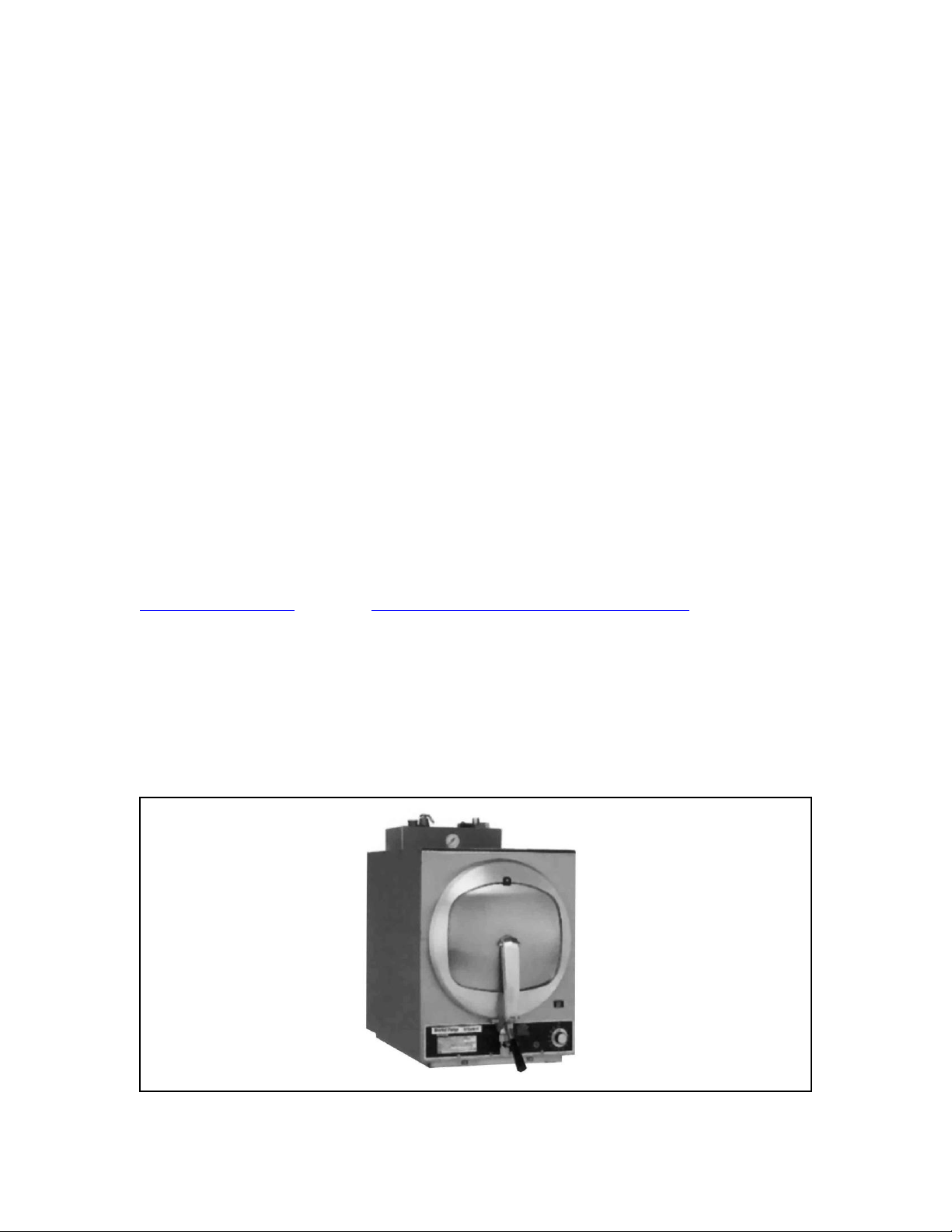
a front mounted panel. (See Figure 1·1)
The major assemblies of the Model ST-AG steam cooker are, the stainless steel
cabinet enclosure, a cooking compartment with pan supports for cooking trays, the
gas burner and ignition control assembly for the direct spark electrode, and a
steam exhaust valve assembly. Located on the lower front panel is a 60-minute
timer with a pilot light (red) "on" indicator and a reset switch marked RESET.
The RESET switch is used to re-cycle the unit in the event of shut off during a
cooking period.
The unit is designed to be mounted on a stand, which is offered and highly
recommended as an optional unit. However, the steam-it unit may be mounted on
any heat- resistant table, counter top etc. as long as certain clearance from
combustible materials are maintained (refer to Section 2 for complete installation
instructions) and the unit is perfectly level.
1.2 BASIC FUNCTIONING
The Model ST·AG steam cooker becomes operational when water is loaded into the
cooking compartment and the 60-minute timer is set to the desired cooking time.
With the time set, the electric ignition comes on, the exhaust valve closes
automatically and the burner ignitor is energized. The gas is ignited by the
electrodes to heat the water in the cooking cylinder.
As the pressure builds up, cold air is forced out of the cylinder through the
thermostatic steam trap. The air will continue to escape as pressure builds up and
the steam trap will close after all the air has been forced out of the cooking
4
compartment. When the pressure reaches approximately 9-10 PSI, the contact on
the pressure switch will close, thereby closing the circuit to the clock motor and
starting the actual cooking time period. When the pressure in the cooking
compartment reaches 15 PSI, the contacts on the pressure switch will open. These
contacts will shut off gas to the main burner when they are open, causing the
pressure to stop rising. When the cooking compartment cools and the pressure
drops to 13 PSI, the contacts on the pressure switch will close gas will flow to the
main burner and be re-ignited by the electrodes. Any number of such "OFF" and
"ON" cycles might occur during the selected cooking time.
1.3 SERVICE
Required service, both preventive and corrective, is explained in Section 6. Should
repairs be required, a network of authorized agencies is available to assist with
prompt service. A current Directory of Authorized
Service Agencies may be obtained by contacting:
Product Service Department
Market Forge Ind.
35 Garvey Street, Everett, Massachusetts 02149
Telephone: (617) 387-4100, (866) 698-3188
custserv@mfii.com, or go to http://www.mfii.com/company/service to find an
authorized parts and service agent near you.
The Model and serial numbers must be referenced when corresponding with
Market Forge. The data plate containing the serial number pertaining to the
equipment is located on the front top, or top (roof) of the cabinet.
Figure 1-1, Model ST-AG Steam-It Pressure Cooker
5

1.4 SPECIFICATIONS
1.4.1 Unit Size
18-3/4 ” Wide x 31-1/2” Front-to-Back (476mm Wide x 800mm Front-to-Back)
1.4.2 Description
The Market Forge Steam-it model ST-AG Direct Spark Ignition Controlled, Gas Fired
Steam-It High Speed Pressure Cooker. Steam-It shall have a 3/16” 5mm aluminum
welded seamless cooking compartment. Exterior finish shall be stainless steel. Door shall
be self-sealing inside type, which can’t be opened under pressure. Door is 12-gauge
stainless steel, removable for cleaning without tools. Door gasket is a one-piece mold,
replaceable without tools or cement.
Unit cooking cycle shall be automatically controlled, requiring only setting of the 0-60
minute timer. Gas firing system shall be controlled by a pilotless solid state, direct spark
ignition control with manual reset button. At the end of the cooking cycle, steam and
condensate shall be exhausted from the cooking compartment and a continuous audible
signal shall sound. Unit shall include a safety valve and a steam pressure gauge, and
shall be completely serviceable from the front.
1.4.3 Cooking Capacity
Cooking compartment shall have a capacity of (3); (3)12” x 20” x 2-1/2” pans (65mm) or
(2) 12” x 20” x 4” pans (10mm).
1.4.4 Operation
Unit shall be rated at 40,000BTU equipped for operation with; Natural or Propane (LP).
Manifold gas pressure shall be 4” (102mm) for natural gas and 10” 254mm for propane
gas. Incoming gas pressure must not exceed 14” 356mm W.C.
1.4.5 Optional Accessories available at extra cost
Pans; 12” x 20” x 2-1/2” solid pan, 12” x 20” x 2-1/2” perforated pan, 12” x 20” x 4” solid
pan, and 12” x 20” x 4” perforated pan. Stainless steel stand, 30” (762mm) high with
shelf, set of (4) stainless steel feet adjustable from 4” (102mm) to 6” (152mm) for
mounting unit on countertop, ball float trap, and a 3/4” (19mm) IPS pressure reducing
valve which will reduce initial pressure of 20 to 50 PSI (1.4-3.5 kg/cm2) to required 15
PSI (1 kg/cm2) operating pressure.
6
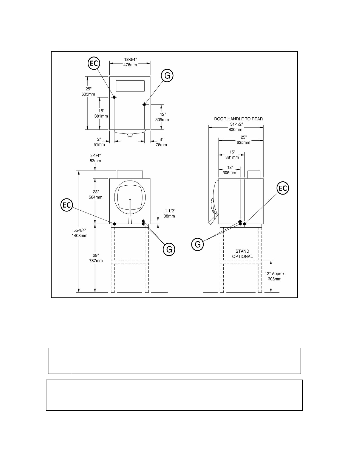
1.5 DETAILS & DIMENSIONS
G
Gas Connection - 3/8” (10mm) IPS. In Canada, 1/2” (13mm) IPS.
EC
Electrical Connection - 120 Volts, 60 Hz, 2 Amps, 1/2” (13mm) Conduit
connection or equivalent.
It is our policy to build equipment which is design certified by U.L., N.S.F. and C.S.A. However, a continuing program of pro duct
improvement makes it necessary to submit new models to the agencies as they are developed and consequently not all models bear
the appropriate agency labels at all times.
Figure 1-2, Dimensions, ST-AG
1.5.1 Service Connections - Gas Operated (Figure 1-2)
NOTE: If the equipment is to be installed where the elevation exceeds 2,000 feet 609.6
meters above sea level, specify installation altitude so that proper orifices can be
provided.
7

SECTION 2 INSTALLATION
2.1 UNPACKING AND ASSEMBLY
The Steam-It cooker is shipped in a carton with protective padding and mounted on a
wooden pallet. Carefully remove the carton, padding and the bolts securing the unit to
the wooden pallet. Inspect assemblies as follows:
1. Inspect unit overall for dents or deformations in stainless steel cabinet
enclosures.
2. Make sure visible attaching hardware for all assemblies are not missing or
damaged.
3. Inspect timer, indicator light, RESET switch and pressure gauge to see they
are not damaged.
4. Remove cap lug from door handle and install handle.
5. Install pan supports so that the horizontal keyhole is at the rear of the
cooking chamber and so that the flange and embossments face the middle of
the chamber.
NOTE: The cooker is carefully inspected and packaged before leaving the factory. If there
are missing components or unit is damaged, notify the carrier or dealer immediately.
2.2 SETTING IN PLACE
If possible, a location should be selected under an exhaust hood, which will remove
small amounts of water vapor emitted when the cooker door is opened. Level the unit in
final location, using the cabinet top as a reference to obtain level adjustment left-toright and front-to-back.
NOTE: If the Steam-it cooker is installed without the optional stand, it may be set on a
heat-resistive table, counter or back bar. The minimum clearance from combustible
construction must be 2 inches from left side, 12 inches from right side and 2 inches from
back.
2.3 GAS CONNECTION
The gas connection is made by removing the lower front panel to gain access to the gas
supply line elbow (Figure 7-3, Index 37).
WARNING: Gas lines should be thoroughly blown out and cleaned before connection
to the Steam-It is made. This will prevent dirt, dust or pipe compound from reaching
the sensitive gas solenoid valve.
8

Installation must conform to the National Fuel Gas Code, ANSI Z223.1-1974.
The gas line should not be smaller than 3/8- inch pipe. A gas shutoff valve is supplied
with the unit and must be installed as close as possible to the gas connection of the
Steam-It, adjacent to the outside of the unit (Refer to Figure 2-1).
2.3.1 Pressure Regulator Setting
The pressure regulator must be set to the proper flow, depending upon the type of gas
used. Setting is as follows:
1. Remove pressure regulator access cover (Figure 7-1, Index 29) and
remove cap from pressure regulator (Figure 7-3lndex 39).
2. For natural or manufactured gas supply, set regulator at 4.0-inch W.C.
(See Subsection 6.4.1.)
3. For propane or butane gas supply set regulator at 10.0-inch W.C. (See
Subsection 6.4.1.)
4. Reinstall protective cap.
5. Check to see that proper burner orifices are installed. Use a #47 OMS
(yellow) for natural gas; a #55 OMS (purple) for propane or butane gases;
a #31 OMS (brown) for manufactured gas. Refer to Figure 7-3, index
43,44 and 45 for proper part numbers.
2.3.2 Canadian Gas Connections
Special instructions are required for in- stalling the Steam-It cooker in Canada
instructions are as follows:
Figure 2-1, Installation of Gas Shut Off Valve
1. Installations in Canada are to be conducted in accordance with C.S.A.
Standard 8149 (Gas Installation Code), C.S.A. Standard C22.1 (Electrical
9

Installation Code) and/or Local Codes.
2. The minimum size supply pipe when used with Natural Gas is 1/2-inch N.P.T.
2.4 ELECTRICAL CONNECTION
Connect 120 volt ac, single phase (2 amp) 60 Hz power supply to the terminal box as
follows:
1. Remove terminal box cover (Figure 7-1, Index 13).
2. Disconnect power from main power source and connect input power
wires to terminals L 1 and L2. Neutral wire connects to terminal L2 and
hot wire to L 1 (refer to wiring diagram, Figure 5-1).
WARNING:
Be sure to ground unit chassis from ground terminal box to an outside ground.
2.5 WATER AND DRAIN CONNECTIONS
The Steam-It cooker design incorporates provisions for manually adding and draining
water, therefore no external connections for water and drain are required.
2.6 INSTALLATION CHECKOUT
After the Steam-It cooker is completely assembled and properly located with electrical
and gas supply connected, the cooker must be given a thorough checkout before being
put into cooking operation.
Before making this checkout the operator must be thoroughly familiar with the
operating procedures in Section 3, and with the function of each control described in
Table 3-1. Reference Figure 3-1 for identification of controls required in the following
procedures. If the unit fails to perform as described below, consult Tables 5-1 and 5-2 of
the troubleshooting guides for corrective action.
2.6.1 Initial Control Settings
Before beginning cooker checkout procedures, perform the following steps:
1. Check to see that 120 volt ac, single phase 60 Hz power is available from
power source and properly connected to unit terminal box,
2. Check to see that the gas supply line shutoff valve is closed,
3. Check to see that the timer is off.
4. Visually check interior of cooking compartment and remove any materials,
papers, etc. Check to see that pan supports are properly installed (refer to
10

paragraph 2,1 step 5) and secured,
5. Check pressure gauge to see that it registers zero pounds
2.6.2 Cooker Checkout
The cooker checkout procedures are as follows:
1. Secure drain plug (Figure 7-6, Index 18), then pour 6 quarts of water into
Steam-It cooking compartment through the door opening,
2. Close the door and lock in position by placing the tongue of the door lock
under the roller on the drain casting and pressing downward until door lock
comes to a firm stop. This lock makes the initial seal. (When steam pressure
builds up in the compartment it will force the door to a tighter closed
position.)
3. Open gas shut-off valve.
4. Turn the steam-it on by setting the timer to the desired cooking time.
Observe pressure increase indicated by pressure gauge.
5. At the close of the preset cooking period, the timer pointer will stop at the
"0" position on the dial. This will shut down the steam-it and automatically
open the exhaust valve. The Buzzer will continue to sound until the dial
pointer is manually turned to the "OFF" position.
6. Observe that the indicator light (Figure 3-1, Item 2) goes out when timer is at
the "O-minute" position.
7. Check the pressure gauge to see that the pressure reads zero.
8. The door will not open while there is steam pressure working against it from
within the cooking compartment. The door must be kept locked until the
cooking cycle has completely finished then the door opened to allow vapor
to clear.
9. Shut off gas supply by closing the gas shutoff valve.
2.6.3 Shutdown Procedure
No special shutdown procedures are required with the exception that the door is left
open, timer must be in the OFF position and the gas supply valve closed, (consult local
codes for daily shut-off requirement).
NOTE: Before using the steam-it for cooking, it is recommended that checkout
operations be performed 2 or 3 times in order to determine that it is working properly
and to insure cleanliness of the cooking compartment.
11

SECTION 3 OPERATION
3.1 OPERATING CONTROLS AND INDICATORS
The controls required to operate the Steam·lt cooker are listed in Table 3-1, together
with a functional description of each. Figure 3-1 shows the physical location of each
control and indicator.
3.2 OPERATING PROCEDURES
The following paragraphs outline the sequence of daily operation for the Steam-It
Model ST-AG cooker. The checkout procedures outlined in Section 2 should be performed prior to daily use for cooking. If any malfunction develops during the normal use
of the cooker, refer to the troubleshooting tables in Section 5.
3.2.1 Preliminary Procedures
Perform the following steps prior to preheating and cooking:
1. Be sure that gas supply is connected to unit, shut off valve is closed and 120volt ac (to operate controls) is connected.
2. Place the drain plug (Figure 7-6 Index 18) located at front center of cooking
compartment securely in place.
3. Check that pan supports are hung on pan support studs on cylinder sidewalls.
The horizontal keyhole on the support should be at rear of compartment and
the vertical keyhole near the front.
4. Insert drain plug, located inside compartment into drain opening and pour
approximately six quarts of water directly into Steam-It compartment.
5. In geographical locations where a high amount of lime and alkaline (salt like
substances) deposits are present in the water supply, add two table- spoons
of vinegar directly into six quarts of water in the Steam-It compartment prior
to starting the cooking cycle. If more water is added to maintain the required
level, an occasional tablespoon of vinegar may be added as well, in order to
compensate for new mineral deposits of the fresh water.
CAUTION: A high degree of mineral salts in the water can cause pitting of the cooking
compartment unless the above directions are followed, the cooking compartment
thoroughly cleaned and drained each night, and the door left open. Do not use
distilled water in the cooking compartment.
3.2.2 Preheating (Figure 3·1)
Before each initial operation of the cooker and at any time when the cooking
12

compartment is cold, a 5- to 8-minute preheating period is required. To preheat the
Figure 3-1, REF
DESCRIPTION
FUNCTION
1
60-Minute Timer
Controls cooking duration. Time is manually set from
0-60 minutes.
2
Indicator Light (RED)
When lit, it indicated that cooking cycle is in
operation.
3
RESET Switch
Used to reset electrical circuits during a power loss or
shutdown. This switch also serves as a protective
device in the even of an electrical overload.
4
Pressure Gauge
Indicated steam pressure PSI & kg/cm2 inside cooking
compartment during cooking cycle.
5
Latch Handle
Secures cooker door in closed position. Lift to open
door.
6
Buzzer
Signals end of cooking cycle (not shown).
7
Drain Plug
Lift to empty water (inside compartment not shown).
cooking compartment, proceed as follows:
1. Insert drain plug (7) into drain opening and add 6 quarts of water into
cooking compartment.
2. Close cooking compartment door and lock securely in place by pressing down
on latch handle (5).
3. Place gas supply shutoff valve in the open position. (Normally left in open
position.)
4. Set 60·minute timer (1) to I minute.
1. Indicator light (2) will come on.
5. When preheating is ended (5 to 8 minutes) and the buzzer (6) sounds, turn
timer (1) to OFF and allow pressure to return to zero PSI on pressure gauge
(4).
6. Open compartment door slightly by pulling up on latch handle (5) to allow
remaining vapor to escape before raising door to full open position.
3.2.3 Cooking Procedures (Figure 3-1)
After the preheating cycle, the compartment may be loaded for cooking. Cooking
procedures are as follows:
1. Carefully slide cooking pans onto pan supports.
2. Close door and lock in position.
3. Set timer (1) to desired cooking time (see Test Kitchen Bulletin #21), turning
timer past desired setting and then back. This will insure accuracy of setting.
TABLE 3-1, CONTROLS AND INDICATORS (See Figure 3-1)
13

Figure 3-1, Steam-It Controls and Indicators
NOTE: The timer will not start until cooking compartment is at a minimum of 9 PSI
pressure (as observed on pressure gauge).
4. At end of cooking cycle, steam will automatically exhaust. When pressure
reaches zero on pressure gauge (4) door can be released by pulling up on
door latch handle (5). Allow a few seconds for remaining vapor to leave
cylinder before completely opening the door. To stop buzzer, turn timer to
"OFF" position.
NOTE: If it is noticed that steam is escaping around door while pressure is building up,
door seal adjustment must be made. Refer to subsection 6.3.1 for instructions.
5. Remove pans and transfer to serving area. Perforated pans, if they are to be
transferred to the serving area, should be underlined with solid pans.
6. Check that water level is at six-quart capacity before starting another cooking
cycle. If strong flavored foods, such as onions or seafood have been cooked,
compartment should be drained, cleaned and flushed and a fresh supply of
water added for the next cooking operation.
7. Clean unit thoroughly at the end of each cooking day (Refer to Section 6.2),
making sure water is emptied and compartment is left dry and the door
open.
3.2.4 Low Water Cut-Off Operation
If the Steam-It is operated with no water or the water has evaporated away, the
14
temperature of the cooking compartment will rise and by heat induction effect the Low
Figure 3-2, Drain Plug
Water Cut-Off. Electric current flow will be broken at the Low Water Cut-Off and the
unit will shut down. With the replacement of water in the cooking compartment, the
unit will again be operative.
NOTE: Should a cooking cycle be interrupted due to safety action of the Low Water CutOff, the food loaded will be under- cooked. Compensation must be made for the cooking
performed and, with proper amount of water in the cooking compartment, a new cycle
determined and set to complete the process.
3.2.5 Shut- Down Procedure
No shut-down procedure is required for the Steam-It cooker except that the timer is in
the OFF position, the compartment door is open, the compartment drained of water,
and the gas supply shutoff valve is closed (only if required by local code).
3.3 CLEANING
After each period of daily operation (more frequently as required to maintain
cleanliness), the Steam-It cooker should be thoroughly cleaned by completing the
following steps:
1. Drain water from compartment by opening drain plug (Figure 3-2) into suitable
container (to hold at least 6 quarts).
2. Remove left and right side pan supports
(Figure 3-3) by lifting front up and forward
to disengage from mounting studs. Wash
with detergent, rinse, and set aside for
reassembly.
3. Wash cooking compartment interior using
mild non-abrasive solution. Rinse and dry
thoroughly.
CAUTION: Failure to wash compartment may
result in pitting of the aluminum surfaces. Use
only mild detergent suitable for use with
aluminum.
4. Replace pan supports in compartment and
leave door open.
3.3.1 Exhaust Silencer
The exhaust silencer (Figure 7-1, Index 51) should
be removed and cleaned periodically. As the cooking compartment is exhausted of
steam through the silencer, impurities can build up from food particles. Cleanings
15

should be frequent enough to prevent clogging. For this reason, the exhaust silencer is
Figure 3-3, Pan Support Removal
made easily accessible and simple to
remove.
To Clean silencer proceed as follows:
1. Remove the one-piece
exhaust silencer from the
unit by unscrewing it in a
counter-clockwise direction
from exhaust valve elbow.
2. Clean the silencer by sloshing
it in hot soapy water and
rinse it in clear water. If dirt
has clogged the Silencer,
presoak it in an alkaline
cleaning solution.
3. After cleaning, stand the silencer on edge to allow it to drain.
4. Screw it back into the elbow of the exhaust valve (clockwise).
16
 Loading...