

Page 1
SERVICE &
PARTS MANUAL
STEAM·IT, STYLE F
GAS OPERATED COOKER
MODELST·AG
Form Number S2127 Printed in U.S.A. Copyright 1977
An
Employee Owned Company
35 Garvey Street, Everett, MA 02149-4403
Page 2
TABLE OF CONTENTS
!'!'.l.;·.1
SECTION 1 INTRODUCTION
1.1 Description .
1.2 Basic Functioning .
1.3 Service.
SECTION 2 INSTALLATION
2.1 Unpacking and Assembly .
2.2 Setting in Place .
2.3 Gas Connection .
2.3.1 Pressure Regulator Setting .
2.3.2 Canadian Gas Connections .
2.4 Electrical Connection .
2.5 Water and Drain Connections .
2.6 Installation Checkout .
2.6.1 Initial Control Setting .
2.6.2 Cooker Checkout .
2.6.3 Shutdown Procedure .
SECTION 3 OPERATION
3.1 Operating Controls and
Indicators .
3.2 Operating Procedures .
3.2.1 Preliminary Procedures .
3.2.2 Preheating .
3.2.3 Cooking Procedures ...
3.2.4 Low Water Cut-Off Operation .
3.2.5 Shut-Down Procedure .
3.3 Cleaning .
3.3.1 Exhaust Silencer .
SECTION 4 PRINCIPLES OF OPERATION
4.1 General .
4.2 Detailed Operation .
4.3 Steam Circuit. . .. . .
4.3.1 Steam Trap .
4.3.2 Pressure Switches .
4.3.3 Steam Pressure Gauge and
Safety Relief Valve .
4.3.4 Steam Exhaust Valve and
Silencer .
4.4 Electrical Circuits .
4.4.1 Control Circuit Components .
1·1
1·1
1.,
2·1
2·1
2·'
2·1
2-1
2·2
2-2
2·2
2-2
2·3
2-3
3-1
3·'
3-1
3·,
3-1
3-3
3-4
3-4
3-4
4-1
4-1
4-1
4·1
4·1
4-1
4-1
4-2
4-2
I .• ".
SECTION 5 TROUBLE-SHOOTING
5.1 General. . . . . . 5·1
5.2 Trouble-Shooting Guides. . . . . .. 5·'
5.3 Electrical Fault Isolation. . . 5·1
54 Electrical Trouble-Shooting
Procedures. . . . . . . . . . . . 5·3
5.4.1 Incoming Power. . . . . . . . . . . . . .. 5·3
5.4.2 Electrical Inspection . . . . . . . 5-5
5.4.3 Direct Spark Ignition Control
System . . . . . . . . . . . . . . 5·5
5.4.4 50-Minute Timer. . . . . . . . . . . . . 5-7
54.5 Solenoid Gas Valve. . . . . . . . . 5-7
5.4.6 Buzzer. . . . . . . . . . . . . . . . . . . . . .. 5-7
5.4.7 Indicator Light.. . ... . .. .... . 5-7
5.4.8 Wiring . . . . . . . . . . 5-8
SECTION 5 MAINTENANCE
6.1 General... . . . . . . . .. 6-1
6.2 Preventive Maintenance. . . . . . .. 6-1
62.1 Door Disassembly and Cleaning. 6-1
6.2.2 Safety Valve Check. . . 6-2
62.3 Door Fulcrum and Drain Cleaning
and Lubrication. . . . . . . . . . . . . .. 6-2
6.2.4 Cooki ng Compartment. . . . . . . .. 6-2
6.2.5 General Inspection . . . . . . . . . . .. 6-2
6.3 Repair and Replacement. . . . . . .. 6-3
6.3.1 Door Assembly. . . . . . . . . . . . . . .. 6-3
6.3.2 Exterior Panel Removal. . . . . . . .. 6-4
6.3.3 Steam Exhaust Valve and Trap
Replacement. . . . . . . . . . . . . . . .. 6-4
6.3.4 Direct Spark Ignition System. . .. 6-4
6.4 Adjustments and Operational
Checks. . . . . . . . . . . . . . . . . . . . .. 6-5
6.4.1 Gas Burners and Pressure
Regulator. . . . . . . . . . . . . . . . . . .. 6-5
6.4.2 Electrode Assembly. . . . . . . . . . .. 6-5
6.4.3 Solenoid Gas Valve. . . . . . . . . . .. 6-5
6.4.4 Timer and Gas Control Switches. 6-5
SECTION 7 ILLUSTRATED PARTS LIST
7.1 General...................... 7-1
7.2 Ordering Information.. 7-1
7.3 Index of Illustrated Parts List - 7-1
III
S2127
Page 3
LIST OF ILLUSTRATIONS
Paoe
SECTION 1 INTRODUCTION
1-1 Model ST-AG Steam-It Cooker ... 1-2
SECTION 2 INSTALLATION
2-1 Installation of Gas Shutoff Valve. 2-2
SECTION 3 OPERATION
3-1 Steam-It Controls and Indicators. 3-2
3-2 Drain Plug. . . . . . . . . . . . . . . . . . .. 3-4
3-3 Pan Support Removal. . . . . . . . .. 3-4
SECTION 4 PRINCIPLES OF OPERATION
4-1 Steam and Gas Circuits. . . . . . .. 4-2
4-2 Pictorial Diagram, Electric
Circuits, 120V 4-3
SECTION 5 TROUBLE-SHOOTING
5-1 Wiring Diagram, Steam-It, 120V,
60 Hz 5-4
5-2 Schematic Diagram, Steam-It,
120V 5-5
5-3 Placement of Flame Current
Meter. . . . . . . . . . . . . . . . . . . . . . .. 5-6
SECTION 6 MAINTENANCE
6-1 Door Spring Disengagement. . .. 6-1
6-2 Door Removal. . . . . . . . . . . . . . . .. 6-2
6-3 Gasket Removal. . . . . . . . . . . . . .. 6-2
6-4 Door Seal Tension Adjustment. .. 6-3
6-5 Air Shutter Adjustment _. 6-5
6-6 Gas Regulator Adjustment. . . . .. 6-5
SECTION 7 ILLUSTRATED PARTS LIST
7-1 Cabinet and Frame Assembly ... 7-2
7-2 Steam Exhaust Valve Assembly .. 7-5
7-3 Burner Chassis Subassembly. " 7-6
7-4 Door Assembly. . . . . . . . . . . . . . .. 7-8
7-5 Door Latch Assembly. . . . . . . . .. 7-9
7-6 Fulcrum and Drain Assembly. . .. 7-10
LIST OF TABLES
Table
SECTION 3 OPERATION
3-1 Controls and Indicators. . . . . . .. 3-3
SECTION 5TROUBLE-SHOOTING
S2127
Page
Table
5-1 Operator's Trouble-Shooting
Guide 5-1
5-2 General Trouble-Shooting Guide. 5·2
5-3 Electrical Fault Isolation Guide.. 5·3
iv
Page
Page 4
SECTION 1 INTRODUCTION
.-~~-- ...-~~.~-.-=-:::-::~=-=-=~-=-=-:~-::::-:::-=-=-=-::-::-:'-~;-::-:-:--;-:---:---;--;-;----;-:------:-7-~--'----'
This service and parts manual contains general information, installation, operation, principles
of operation, trouble-shooting, and maintenance information for the Market Forge Steam-It,
Style F,Gas
IS Identified and shown in an accompanying exploded view.
Operated,
Model ST-AG. Also included is a parts list in which each replaceable part
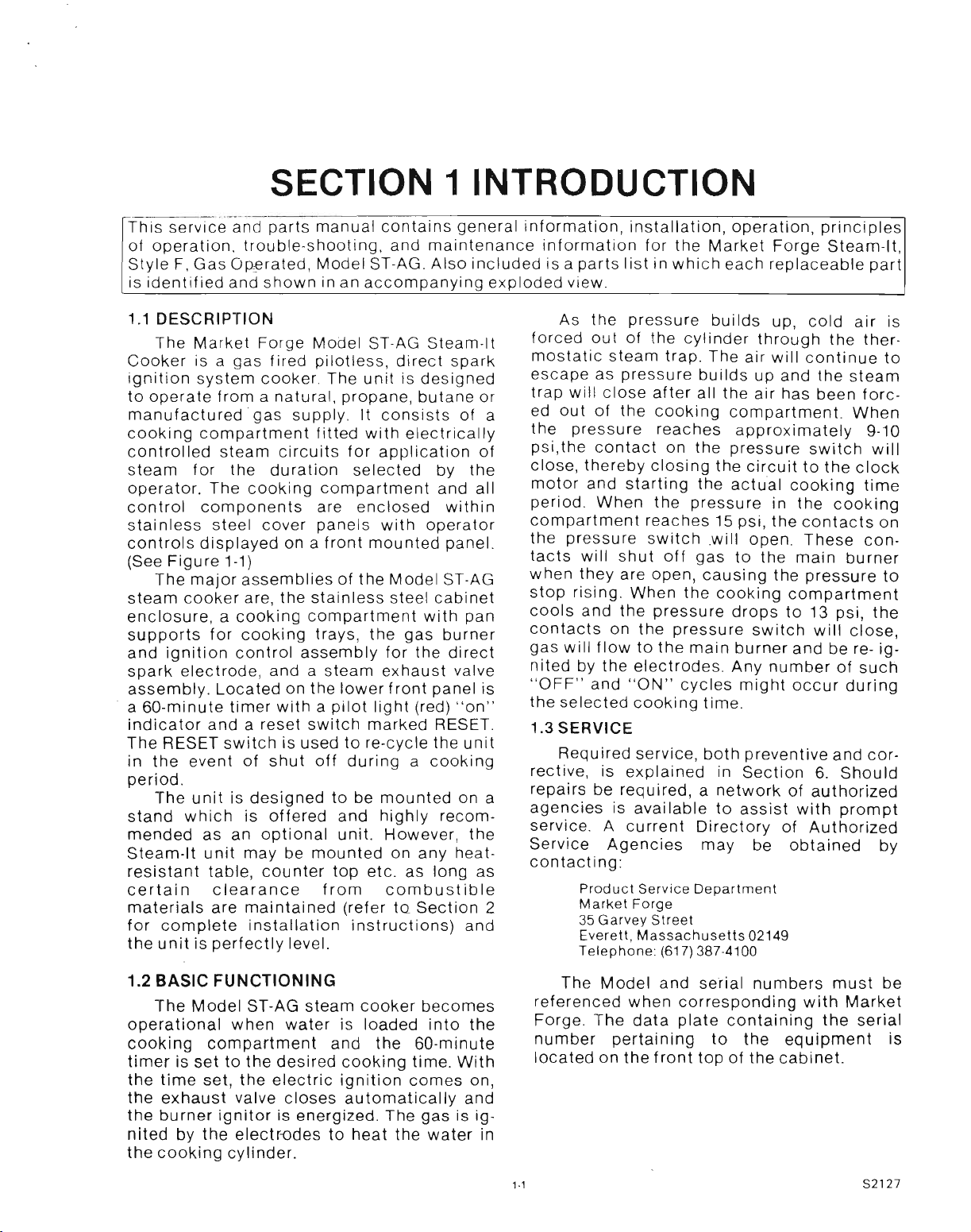
1.1 DESCRIPTION
The Market Forge Model ST-AG Steam-It
Cooker is a gas fired pilotless, direct spark
ignition system cooker. The unit is designed
to operate from a natural, propane, butane or
manufactured gas supply. It consists of a
cooking compartment fitted with electrically
controlled steam circuits for application of
steam for the duration selected by the
operator. The cooking compartment and all
control components are enclosed within
stainless steel cover panels with operator
controls displayed on a front mounted panel.
(See Figure 1-1)
The major assemblies of the Model ST-AG
steam cooker are, the stainless steel cabinet
enclosure, a cooking compartment with pan
supports for cooking trays, the gas burner
and ignition control assembly for the direct
spark electrode, and a steam exhaust valve
assembly. Located on the lower front panel is
a 50-minute timer with a pilot light (red) "on"
indicator and a reset switch marked RESET.
The RESET switch is used to re-cycle the unit
in the event of shut off during a cooking
period.
The unit is designed to be mounted on a
stand which is offered and highly recommended as an optional unit. However, the
Steam-It unit may be mounted on any heat-
resistant table, counter top etc. as long as
certain clearance from combustible
materials are maintained (refer to Section 2
for complete installation instructions) and
the unit is perfectly level.
As the pressure builds up, cold air is
forced out of the cylinder through the thermostatic steam trap. The air will continue to
escape as pressure builds up and the steam
trap will close after all the air has been forc-
ed out of the cooking compartment. When
the pressure reaches approximately 9-10
psi,the contact on the pressure switch will
close, thereby closing the circuit to the clock
motor and starting the actual cooking time
period. When the pressure in the cooking
compartment reaches 15 psi, the contacts on
the pressure switch will open. These contacts will shut off gas to the main burner
when they are open, causing the pressure to
stop rising. When the cooking compartment
cools and the pressure drops to 13 psi, the
contacts on the pressure switch will close
gas will flow to the main burner and be re- ig:
nited by the electrodes. Any number of such
"OFF" and "ON" cycles might occur during
the selected cooking time.
1.3
SERVICE
Required service, both preventive and corrective, is explained in Section 5. Should
repairs be required, a network of authorized
agencies is available to assist with prompt
service. A current Directory of Authorized
Service Agencies may be obtained by
contacting:
Product Service Department
Market Forge
35 Garvey Street
Everett, Massachusetts 02149
Telephone: (617) 387·4100
1.2 BASIC FUNCTIONING
The Model ST-AG steam cooker becomes
operational when water is loaded into the
cooking compartment and the 60-minute
timer is set to the desired cooking time. With
the time set, the electric ignition comes on,
the exhaust valve closes automatically and
the burner ignitor is energized. The gas is ig-
nited by the electrodes to heat the water in
the cooking cylinder.
The Model and serial numbers must be
referenced when corresponding with Market
Forge. The data plate containing the serial
number pertaining to the equipment is
located on the front top of the cabinet.
1·1
S2127
Page 5
SECTION 2 INSTALLATION
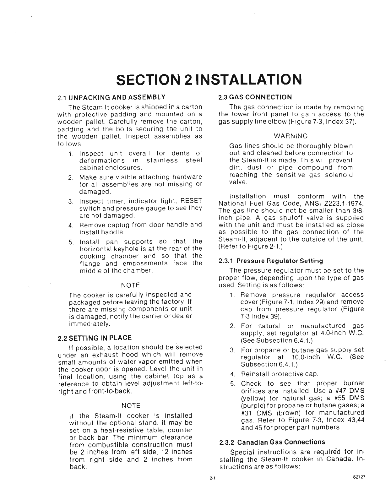
2.1 UNPACKING AND ASSEMBLY
The Stearn-It cooker is shipped in a carton
with protective padding and mounted on a
wooden pallet. Carefully remove the carton,
padding and the bolts securing the unit to
the wooden pallet. Inspect assemblies as
follows:
1. Inspect unit overall for dents or
deformations in stainless steel
cabinet enclosures.
2. Make sure visible attaching hardware
for all assemblies are not missing or
damaged.
3. Inspect timer, indicator light, RESET
switch and pressure gauge to see they
are not damaged.
4. Remove caplug from door handle and
install handle.
5. Install pan supports so that the
horizontal keyhole is at the rear of the
cooking chamber and so that the
flange and embossments face the
middle of the chamber.
NOTE
The cooker is carefully inspected and
packaged before leaving the factory. If
there are missing components or unit
is damaged, notify the carrier or dealer
immediately.
2.2 SETTING IN PLACE
If possible, a location should be selected
under an exhaust hood which will remove
small amounts of water vapor emitted when
the cooker door is opened. Level the unit in
final location, using the cabinet top as a
reference to obtain level adjustment left-toright and tront-to-back.
NOTE
If the Steam-It cooker is installed
without the optional stand, it may be
set on a heat-resistive table, counter
or back bar. The minimum clearance
from combustible construction must
be 2 inches from left side, 12 inches
from right side and 2 inches from
back.
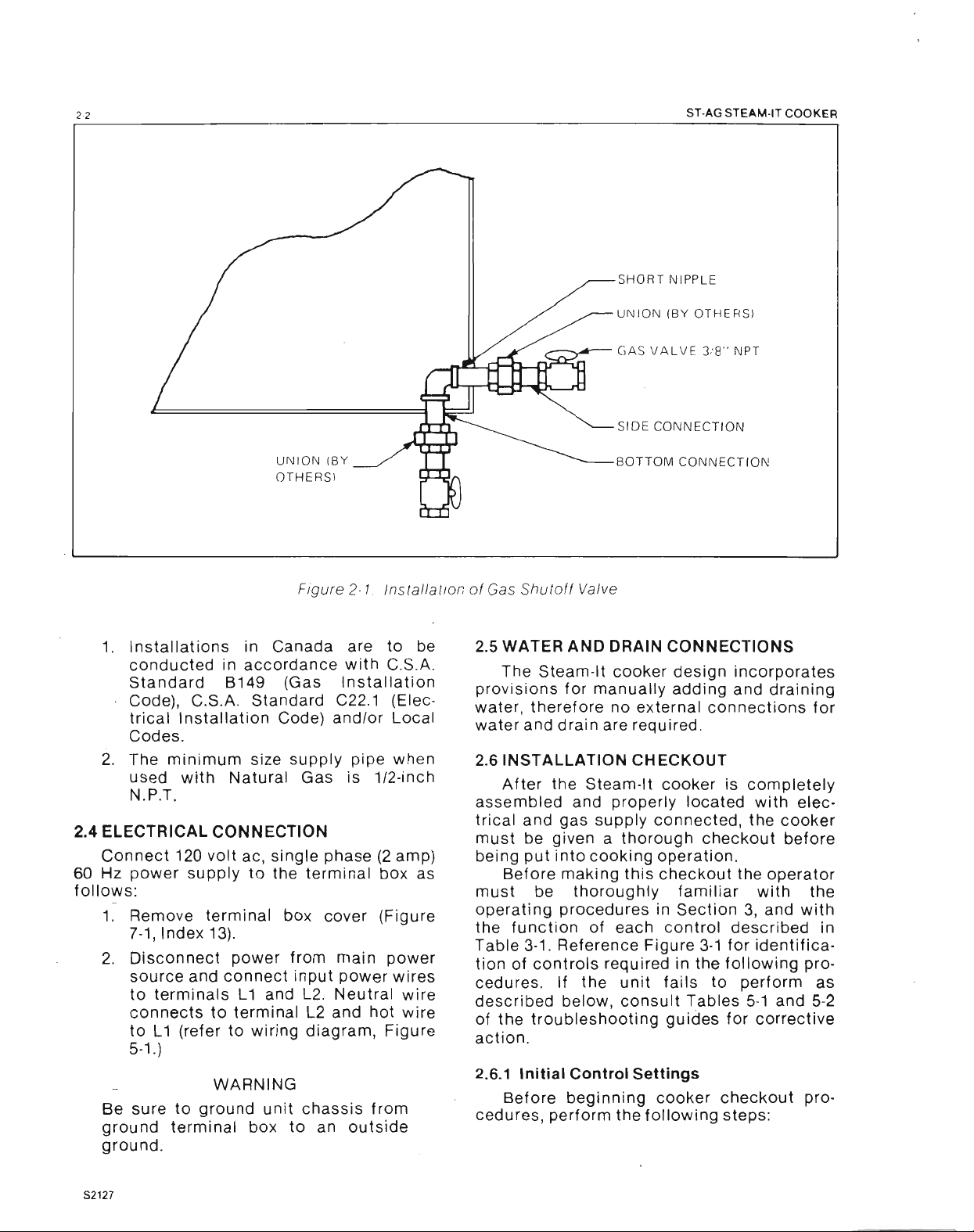
2.3 GAS CONNECTION
The gas connection is made by removing
the lower front panel to gain access to the
gas supply line elbow (Figure 7-3, Index 37).
WARNING
Gas lines should be thoroughly blown
out and cleaned before connection to
the Steam-It is made. This will prevent
dirt, dust or pipe compound from
reaching the sensitive gas solenoid
valve.
Installation must conform with the
National Fuel Gas Code, ANSI Z223.1-1974.
The gas line should not be smaller than 3/8inch pipe. A gas shutoff valve is supplied
with the unit and must be installed as close
as possible to the gas connection of the
Steam-It, adjacent to the outside of the unit.
(Refer to Figure 2-1.)
2.3.1
Pressure Regulator Setting
The pressure regulator must be set to the
proper flow, depending upon the type of gas
used. Setting is as follows:
1. Remove pressure regulator access
cover (Figure 7-1, Index 29) and remove
cap from pressure regulator (Figure
7-3 Index 39).
2. For natural or manufactured gas
supply, set regulator at 4.0·inch W.C.
(See Subsection 6.4.1.)
3. For propane or butane gas supply set
regulator at 10.0-inch W.C. (See
Subsection 6.4.1.)
4. Reinstall protective cap.
5. Check to see that proper burner
orifices are installed. Use a #47 OMS
(yellow) for natural gas; a #55 OMS
(purple) for propane or butane gases; a
#31 OMS (brown) for manufactured
gas. Refer to Figure 7-3, Index 43,44
and 45 for proper part numbers.
2.3.2 Canadian Gas Connections
Special instructions are required for in-
stalling the Steam-It cooker in Canada. Instructions are as follows:
2·'
SZ127
Page 6
2·2
SHORT NIPPLE
UNION (BY OTHERS)
----- GAS VALVE 3/8" NPT
SIDE CONNECTION
ST·AG STEAM·IT COOKER
UNION (BY
OTHERS)
Figure 2·1
tnstetteuon
1. Installations in Canada are to be
conducted in accordance with C.S.A.
Standard B149 (Gas Installation
Code), C.S.A. Standard C22.1 (Electrical Installation Code) and/or Local
Codes.
2. The minimum size supply pipe when
used with Natural Gas is 1/2-inch
N.P.T.
2.4 ELECTRICAL CONNECTION
Connect 120 volt aCt single phase (2 amp)
60 Hz power supply to the terminal box as
follows:
1. Remove terminal box cover (Figure
7-1, Index 13).
2. Disconnect power from main power
source and connect input power wires
to terminals L1 and L2. Neutral wire
connects to terminal L2 and hot wire
to L1 (refer to wiring diagram, Figure
5-1.)
WARNING
Be sure to ground unit chassis from
ground terminal box to an outside
ground.
BOTTOM CONNECTION
of Gas Shutoff Valve
2.5 WATER AND DRAIN CONNECTIONS
The Stearn-lt cooker design incorporates
provisions for manually adding and draining
water, therefore no external connections for
water and drain are required.
2.6 INSTALLATION CHECKOUT
After the Steam-It cooker is completely
assembled and properly located with electrical and gas supply connected, the cooker
must be given a thorough checkout before
being put into cooking operation.
Before making this checkout the operator
must be thoroughly familiar with the
operating procedures in Section 3, and with
the function of each control described in
Table 3-1. Reference Figure 3-1 for identifica-
tion of controls required in the following procedures. If the unit fails to perform as
described below, consult Tables 5-1 and 5-2
of the troubleshooting guides for corrective
action.
2.6.1
Initial Control Settings
Before beginning cooker checkout procedures, perform the following steps:
S2127
Page 7
INTRODUCTION
1.
Check to see that
120
volt ac. single
phase 60 Hz power is available from
power source and properly connected
to unit terminal box.
2. Check to see that the gas supply line
shutoff valve is closed.
3. Check to see that the timer is off
4 Visually check interior of cooking
compartment and remove any
materials, papers, etc. Check to see
that pan supports are properly install-
2.1
ed (refer to par aqraph
step 5) and
secured.
5 Check pressure gauge to see that it
registers zero pounds.
2.6.2
Cooker Checkout
The cooker checkout procedures are as
follows:
1. Secure drain plug (Figure 7-6, Index
18), then pour 6 quarts of water into
Steam-It cooking compartment
through the door opening.
2. Close the door and lock in position by
placing the tongue of the door lock
under the roller on the drain casting
and pressing downward until door
lock comes to a firm stop. This lock
makes the initial seal. (When steam
pressure builds up in the compartment it will force the door to a tighter
closed position.)
3. Open gas shut-off valve.
4. Turn the Steam-It on by setting the
timer to the desired cooking time.
Observe pressure increase indicated
by pressure gauge.
5. At the close of the preset cooking
period, the timer pointer will stop at
the "0" position on the dial. This will
shut down the Steam-It and
automatically open the exhaust valve.
The Buzzer will continue to sound un-
til the dial pointer is manually turned
to the "OFF" position.
6. Observe that the indicator light
(Figure 3·1, Item 2) goes out when
timer is at the "O·minute" position.
7. Check the pressure gauge to see that
the pressure reads zero.
8. The door will not open while there is
steam pressure working against it
from within the cooking compartment.
The door must be kept locked until the
cooking cycle has completely finished, then the door opened to allow
vapor to clear.
9. Shut off gas supply by closing the gas
shutoff valve.
2.6.3
Shutdown Procedure
No special shutdown procedures are
required with the exception that the door is
left open, timer must be in the OFF position
and the gas supply valve closed, (consult
local codes for daily shut-off requirement.)
NOTE
Before using the Steam-It for cooking,
it is recommended that checkout
operations be performed 2 or 3 times
in order to determine that it is working
properly and to insure cleanliness of
the cooking compartment.
23
S2127
Page 8
SECTION 3 OPERATION
3.1
OPERATING CONTROLS AND
INDICATORS
The controls required to operate the
Steam-It cooker are listed in Table 3-1,
together with a functional description of
each. Figure 3-1 shows the physical location
of each control and indicator.
3.2
OPERATING PROCEDURES
The following paragraphs outline the
sequence of daily operation for the Steam-It
Model ST-AG cooker. The checkout procedures outlined in Section 2 should be performed prior to daily use for cooking. If any
malfunction develops during the normal use
of the cooker, refer to the troubleshooting
tables in Section 5.
3.2.1
Preliminary Procedures
Perform the following steps prior to
preheating and cooking:
1. Be sure that gas supply is connected
to unit, shut off valve is closed and 120
volt ac (to operate controls) is connected.
2. Place the drain plug (Figure 7-6 Index
18) located at front center of cooking
compartment securely in place.
3. Check that pan supports are hung on
pan support studs on cylinder side
walls. The horizontal keyhole on the
support should be at rear of compart-
ment and the vertical keyhole near the
front.
4. Insert drain plug, located inside
compartment into drain opening and
pour approximately six quarts of water
directly into Steam-It compartment.
5. In geographical locations where a
high amount of lime and alkaline (salt
like substances) deposits are present
in the water supply, add two table-
spoons of vinegar directly into six
quarts of water in the Steam-It com-
partment prior to starting the cooking
cycle. If more water is added to main-
tain the required level, an occasional
tablespoon of vinegar may be added
as well, in order to compensate for
new mineral deposits of the fresh
water.
CAUTION
A high degree of mineral salts in the
water can cause pitting of the cooking
compartment unless the above directions are followed, the cooking compartment thoroughly cleaned and
drained each night, and the door left
open. Do not use distilled water in the
cooking compartment.
3.2.2
Preheating (Figure
Before each initial operation of the
cooker and at any time when the cooking
compartment is cold, a 5- to 8-minute
preheating period is required. To preheat the
cooking compartment, proceed as follows:
1. Insert drain plug (7) into drain opening
and add 6 quarts of water into cooking
compartment.
2. Close cooking compartment door and
lock securely in place by pressing
down on latch handle (5).
3. Place gas supply shutoff valve in the
open position. (Normally left in open
position.)
4. Set 60-minute timer (1) to I minute.
Indicator light (2) will come on.
5. When preheating is ended (5 to 8
minutes) and the buzzer (6) sounds,
turn timer (1) to OFF and allow
pressure to return to zero psi on
pressure gauge (4).
6. Open compartment door slightly by
pulling up on latch handle (5) to allow
remaining vapor to escape before raising door to full open position.
3-1)
3.2.3 Cooking Procedures (Figure 3-1)
After the preheating cycle, the compartment may be loaded for cooking. Cooking
procedures are as follows:
1. Carefully slide cooking pans onto pan
supports.
2. Close door and lock in position.
3, Set timer (1) to desired cooking time
(see Test Kitchen Bulletin #21), turning
timer past desired settin-g and then
back. This will insure accuracy of
3-1
setting.
S2127
Page 9
OPERATION
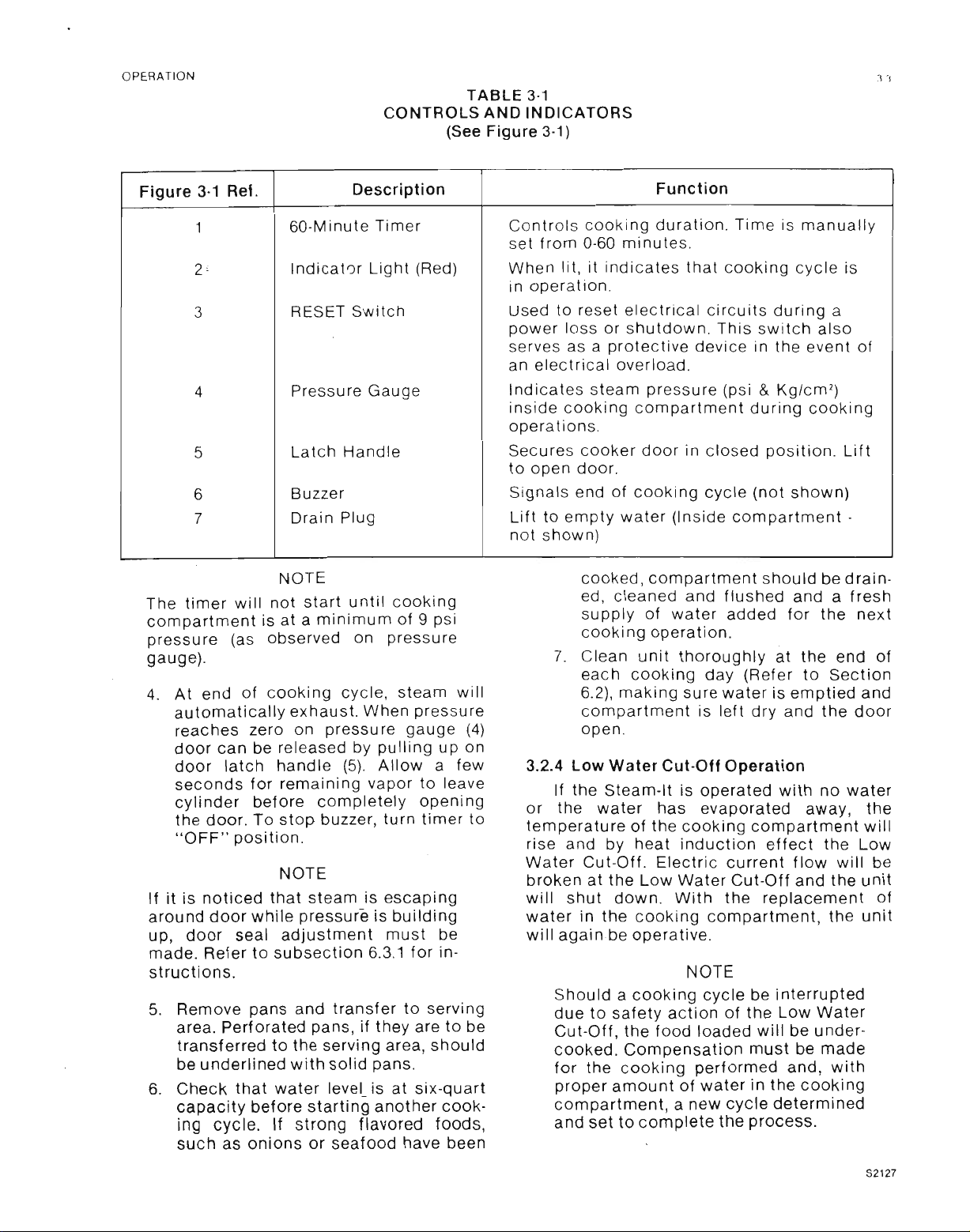
TABLE 3-1
CONTROLS AND INDICATORS
(See Figure 3-1)
Figure 3-1
1
2'
3
4
5
6
7
Ref.
60-Minute Timer
indicator Light (Red) When lit, it indicates that cooking cycle is
RESET Switch Used to reset electrical circuits during a
Pressure Gauge
Latch Handle Secures cooker door in closed position. Lift
Buzzer
Drain Plug
Description
NOTE
The timer will not start until cooking
compartment is at a minimum of 9 psi
pressure (as observed on pressure
gauge).
4. At end of cooking cycle, steam will
automatically exhaust. When pressure
reaches zero on pressure gauge (4)
door can be released by pulling up on
door latch handle (5). Allow a few
seconds for remaining vapor to leave
cylinder before completely opening
the door. To stop buzzer, turn timer to
"OFF" position.
NOTE
If it is noticed that steam is escaping
around door while pressure is building
up, door seal adjustment must be
made. Refer to subsection 6.3.1 for in-
structions.
5. Remove pans and transfer to serving
area. Perforated pans, if they are to be
transferred to the serving area, should
be underlined with solid pans.
6. Check that water leveL is at six-quart
capacity before starting another cooking cycle. If strong flavored foods,
such as onions or seafood have been
Function
Controls cooking duration. Time is manually
set from 0-60 minutes.
in operation.
power loss or shutdown. This switch also
serves as a protective device in the event of
an electrical overload.
Indicates steam pressure (psi&Kg/cm
2
)
inside cooking compartment during cooking
operations.
to open door.
Signals end of cooking cycle (not shown)
Lift to empty water (Inside compartment -
not shown)
cooked, compartment should be drain-
ed, cleaned and flushed and a fresh
supply of water added for the next
cooking operation.
7. Clean unit thoroughly at the end of
each cooking day (Refer to Section
6.2), making sure water is emptied and
compartment is left dry and the door
open.
3.2.4 Low Water Cut-Off Operation
If the Steam-It is operated with no water
or the water has evaporated away, the
temperature of the cooking compartment will
rise and by heat induction effect the Low
Water Cut-Off. Electric current flow will be
broken at the Low Water Cut-Off and the unit
will shut down. With the replacement of
water in the cooking compartment, the unit
will againbe operative.
NOTE
Should a cooking cycle be interrupted
due to safety action of the Low Water
Cut-Off, the food loaded will be undercooked. Compensation must be made
for the cooking performed and, with
proper amount of water in the cooking
compartment, a new cycle determined
and set to complete the process.
S2127
Page 10
3·4
3.2.5 shut- Down Procedure
No shut-down procedure is required for
the Stearn-It cooker except that the timer is
in the OFF position, the compartment door is
open, the compartment drained of water, and
the gas supply shutoff valve is closed (only if
required by local code).
3.3 CLEANING
After each period of daily operation (more
frequently as required to maintain
cleanliness), the Steam-It cooker should be
thoroughly cleaned by completing the following steps:
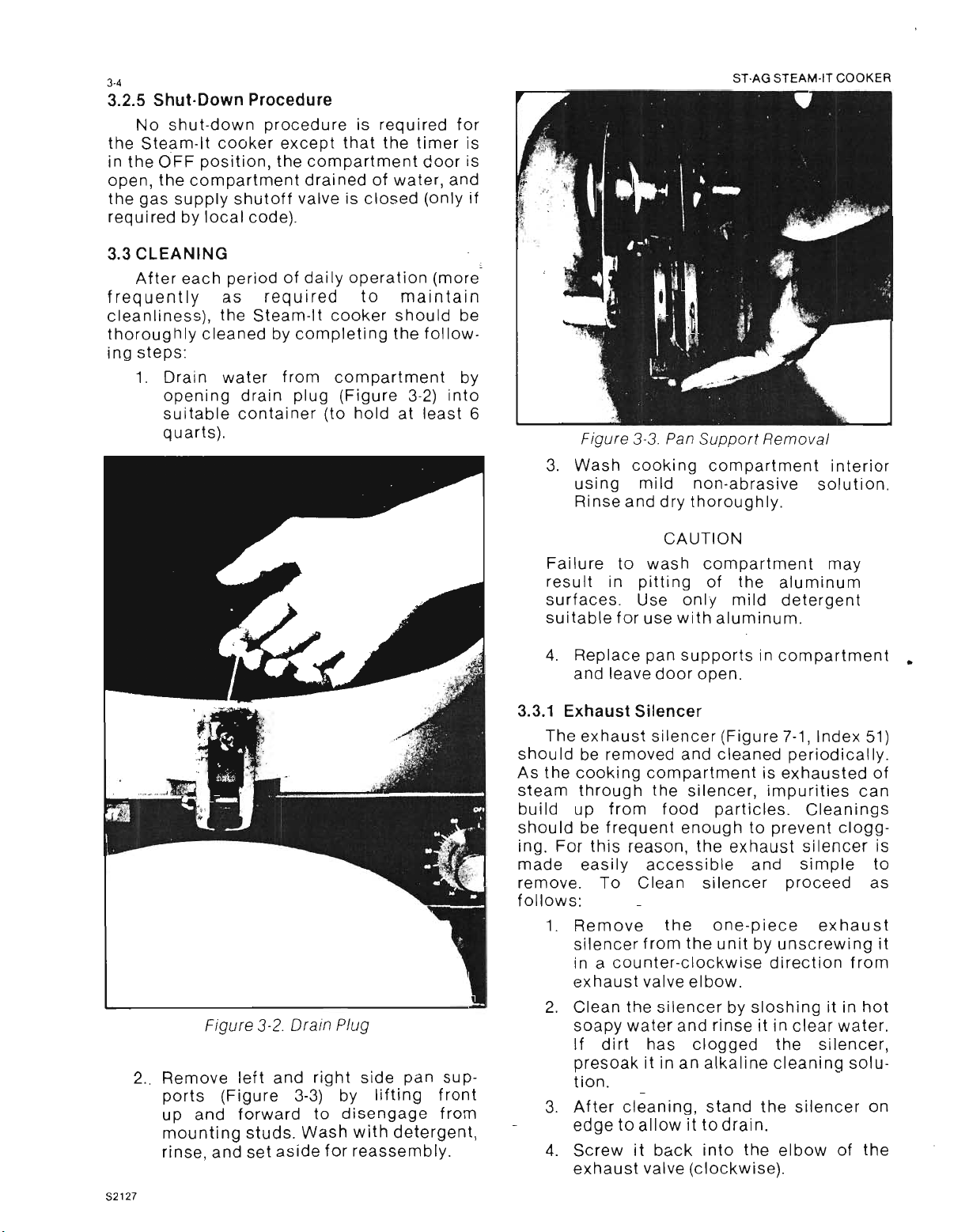
1. Drain water from compartment by
opening drain plug (Figure 3-2) into
suitable container (to hold at least 6
quarts).
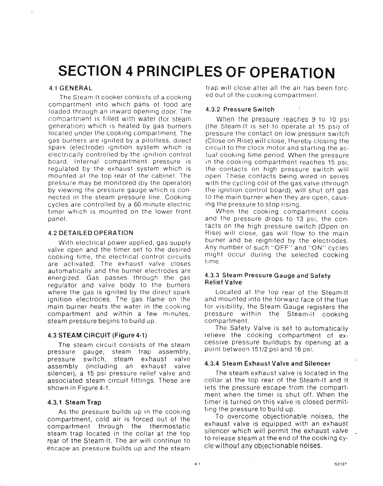
ST·AG STEAM·IT COOKER
Figure 3-3. Pan Support Removal
3. Wash cooking compartment interior
using mild non-abraslve solution.
Rinse and dry thoroughly.
Figure
3-2.
Drain Plug
2.. Remove left and right side pan supports (Figure 3·3) by lifting front
up and forward to disengage from
mounting studs. Wash with detergent,
rinse, and set aside for reassembly.
52127
CAUTION
Failure to wash compartment may
result in pitting of the aluminum
surfaces. Use only mild detergent
suitable for use with aluminum.
4. Replace pan supports in compartment •
and leave door open.
3.3.1 Exhaust Silencer
The exhaust silencer (Figure 7-1, Index 51)
should be removed and cleaned periodically.
As the cooking compartment is exhausted of
steam through the silencer, impurities can
build up from food particles. Cleanings
should be frequent enough to prevent clogging. For this reason, the exhaust silencer is
made easily accessible and simple to
remove. To Clean silencer proceed as
follows:
1. Remove the one-piece exhaust
silencer from the unit by unscrewing it
in a counter-clockwise direction from
exhaust valve elbow.
2. Clean the silencer by sloshing it in hot
soapy water and rinse it in clear water.
If
dirt has clogged the silencer,
presoak it in an alkaline cleaning solution.
3. After cleaning, stand the silencer on
edge to allow it to drain.
4. Screw it back into the elbow of the
exhaust valve (clockwise).
Page 11
SECTION 4 PRINCIPLES OF OPERATION
4.1 GENERAL
The Stearn-ltcooker consists of a cooking
compartment into which pans of food are
loaded through an inward opening door. The
compartment is filled with water (for steam
generation) which is heated by gas burners
located under the cooking compartment. The
gas burners are ignited by a pilotless, direct
spark (electrode) ignition system which is
electrically controlled by the ignition control
board. Internal compartment pressure is
regulated by the exhaust system which is
mounted at the top rear of the cabinet. The
pressure may be monitored (by the operator)
by viewi ng the pressure gauge which is connected in the steam pressure line. Cooking
cycles are controlled by a 60-minute electric
timer which is mounted on the lower front
panel.
4.2 DETAILED OPERATION
With electrical power applied, gas supply
valve open and the timer set to the desired
cooking time, the electrical control circuits
are activated. The exhaust valve closes
automatically and the burner electrodes are
energized. Gas passes through the gas
regulator and valve body to the burners
where the gas is ignited by the direct spark
ignition electrodes. The gas flame on the
main burner heats the water in the cooking
compartment and within a few minutes,
steam pressure begins to build up.
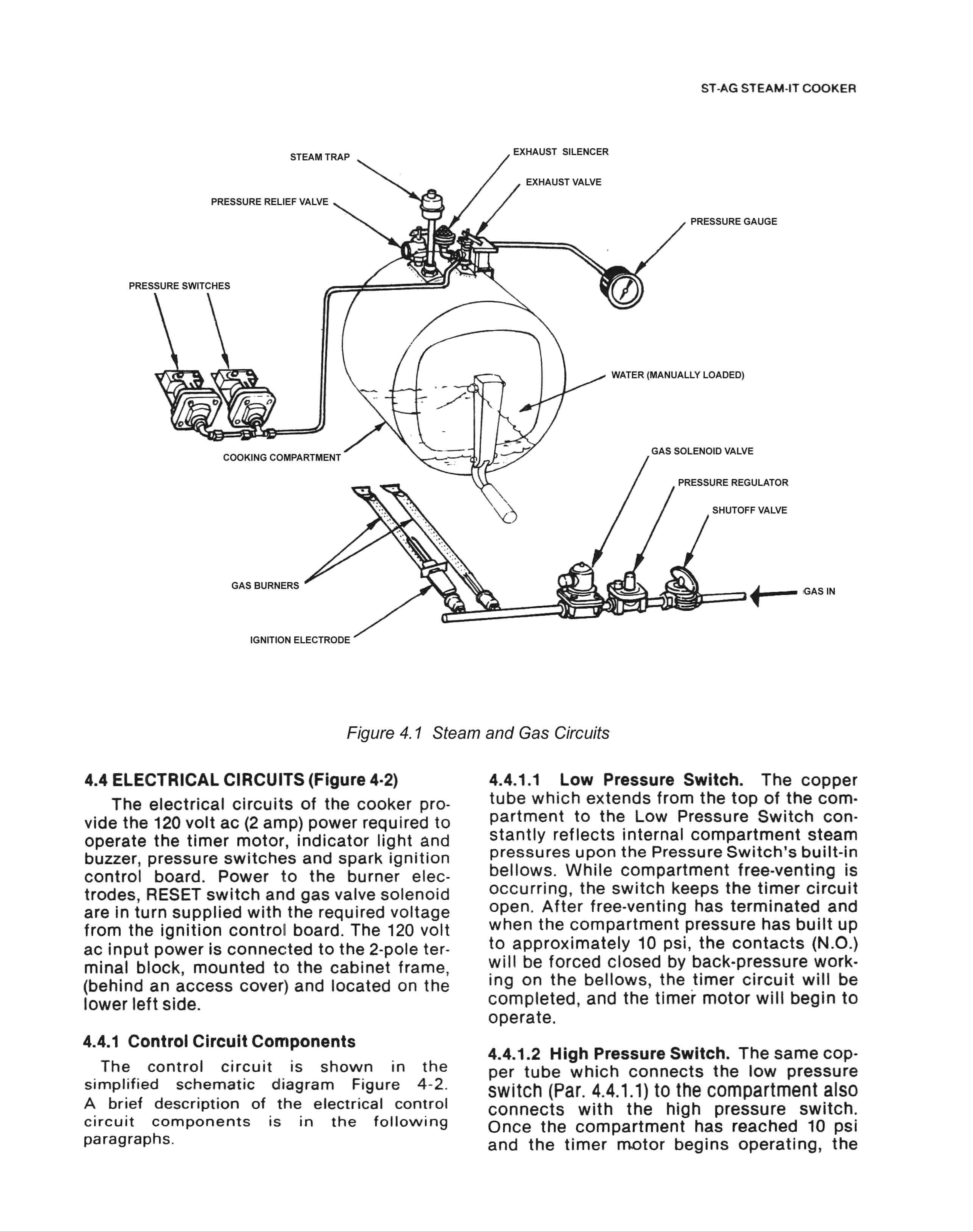
4.3 STEAM CIRCUIT (Figure 4·1)
The steam circuit consists of the steam
pressure gauge, steam trap assembly,
pressure switch, steam exhaust valve
assembly (including an exhaust valve
silencer), a 15 psi pressure relief valve and
associated steam circuit fittings. These are
shown in Figure 4·1.
4.3.1 Steam Trap
As the pressure builds up in the cooking
compartment, cold air is forced out of the
compartment through the thermostatic
steam trap located in the collar at the top
rear of the Steam·lt. The air will continue to
escape as pressure builds up and the steam
trap will close after all the air has been forced out of the cooking compartment
4.3.2 Pressure Switch
When the pressure reaches 9 to 10 psi
(the Steam-It is set to operate at 15 psi) of
pressure the contact on low pressure switch
(Close on Rise) will close, thereby closing the
circuit to the clock motor and starting the actual cooking time period. When the pressure
in the cooking compartment reaches 15 psi,
the contacts on high pressure switch will
open These contacts being wired in series
with the cycling coil of the gas valve (through
the ignition control board), will shut off gas
to the main burner when they are open, causing the pressure to stop rising.
When the cooking compartment cools
and the pressure drops to 13 psi, the contacts on the high pressure switch (Open on
Rise) will close, gas will flow to the main
burner and be reignited by the electrodes.
Any number of such "OFF" and "ON" cycles
might occur during the selected cooking
time.
4.3.3 Steam Pressure Gauge and Safety
Relief Valve
Located at the top rear of the Steam-It
and mounted into the forward face of the flue
for visibility, the Steam Gauge registers the
pressu re within the Steam-It cooking
compartment.
The Safety Valve is set to automatically
relieve the cooking compartment of ex·
cessive pressure buildups by opening at a
point between 151/2 psi and 16 psi.
4.3.4 Steam Exhaust Valve and Silencer
The steam exhaust valve is located in the
collar at the top rear of the Steam-lt and it
lets the pressure escape from the cornpartment when the timer is shut off. When the
timer is turned on this valve is closed permitting the pressure to build up.
To overcome objectionable noises, the
exhaust valve is equipped with an exhaust
silencer which will permit the exhaust valve _
to release steam at the end of the cooking
cv-
cle without any objectionable noises.
4·1
S2127
Page 12
Page 13

PRINCIPLES OF OPERATION
4-3
120V.60Hl
INPUT
LOW WATER
CUTOFF SWITCH
NC
TIMER
INDICATOR
LIGHT
EXHAUST
VALVE
NO
r-----,
I I
I
I
I
COIL
L
-----
J
I
IGNITION
ELECTRODE
I
I
I
I
I
I
I
L _
LOW PRESSURE
SWITCH NO
r-------,
I
I
I
I
I I
L
r------------,
I
I
I
I
J
MOTOR
____ ...J
4
I
I
I
I
I
I
I
I
HIGH PRESSURE
SWITCH NC
r------l
I I
I I
I I
I I
I
I I
L_ J
BUZZER
I
~ ~ I
,-----,
I
I
I ~~--~--.
I
COIL I SPARK IGNITION CONTROL
L .J
GAS SOLENOID VALVE NC
NOTE: ALL CONTROLS SHOWN IN THE OPERATING POSITION_
Figure
4-2.
:
I:
I
I L ~
Pictoral Diagram, Electric Circuits,
~~
~I--_
RESETNe
I _
I
120V
52127
Page 14

44
pressure will continue to rise until the con-
tacts of the high pressure switch (N.C.) are
forced open (at approx 13 psi) by pressure
working on the bellows. When contacts are
opened the gas solenoid valve is closed by
the ignition control board. As the cornpartment cools the pressure drops until the con-
tacts return to the closed position, activating
the spark ignition control board in the firing
sequence.
4.4.1.3 60·Minute Timer. The timer contains
a 120 volt ac synchronous motor which drives
a timing dial through a gear reduction and
clutch mechanism. The timer dial is manually
set for any interval of operation from O· to
minutes as read on the calibrated dial face.
The manual rotation of the dial moves the
common element (1) of the timer switch from
the neutral position to contact (3) which connects with pressure controls and gas firing
system. The Steam-It is put into an automatic
cycle of cooking with the setting of the Timer
to any of its calibrated periods of cooking. Its
timing cycle, however, is automatically
delayed by the Low Pressure Switch until
free-ventinp has occurred and a cornpartment pressure buildup to 10 psi has been
reached. When the timer motor has operated
for the preset duration, the common element
is transferred to contact (4), ending gas firing
cycle, returning exhaust valve to open position and energizing the buzzer. Contact to the
buzzer circuit remains closed until the dial is
manually turned to the OFF position, returning the common element (1) of the timer
switch to the neutral position.
4.4.1.4
which operates by oscillation of a striker
against the core of an electromagnet. When
the timer dial reaches "O-minutes" the buzzer
coil is energized to sound the buzzer. Move-
ment of the timer dial to the OFF position
opens the contact to the buzzer coil to shut it
off.
Buzzer. The buzzer is an alarm device
60·
ST·AG STEAM·IT COOKER
4.4.1.5 Indicator light. The Indicator Light is
located at the lower right front of the front
panel adjacent to the timer knob. It is
to operate only when the timer is set to
cooking cycle. The circuit will be broken
when the timer returns to the "ZERO" posttion. Thus, when lit, it signifies that the
Steam-It is in the process of cooking.
4.4.1.6 RESET Switch. The RESET switch is
located on the left side of the lower front
panel. The switch is used to reset the
trical circuits of the ignition control board in
the event of an ignition failure
4.4.1.7 Direct Spark Ignition System. The
direct spark ignition system consists of the
electrodes, ignition control board and
associated wiring. On a call for heat, input
power is applied to the control board,
sparking is then initiated and the gas valve
is energized. Sparking continues with the
gas valve powered for a "trial for ignition"
period of 3.3 seconds. If flame has not been
established by the end of the trial
the system will lock out, the gas valve will
close, and the reset function will then trip
out. Reset action is manually accomplish.
by pressing RESET switch. In normal oper ,
tion, as soon as flame is established and
proven by the flame sensing circuitry,
sparking will cease immediately and the
system will remain "on", monitoring the
flame until the end of the duty cycle.
Should flame-out occur during the duty
cle, the system will reactivate the spark to
provide for reignition.
The flame will either be reestablished or
the system will lock out in the normal manner. Should lock out occur, the system is
reactivated with the RESET switch for
recycling. Control for operation of the
solenoid gas valve, gas pressure switch and
RESET switch is provided from the circuits
contained on the ignition control board.
wirr
etec-
period,
cv-
S2127
Page 15

SECTION 5 TROUBLE-SHOOTING
5.1
GENERAL
The information cin this section is in-
tended to assist both the operator and service personnel in locating the general source
of problems which
Steam-It cooker. Before following any of the
procedures given in this section, the operator
should be thoroughly familiar with the
operating instructions and the function of all
controls which are described in Section 3. If
the problem cannot be readily corrected, the
operator should contact the nearest authorized Market Forge service agency for
assistance.
may
occur with the
TABLE 5-1
OPERATOR'S TROUBLE-SHOOTING GUIDE
5.2
TROUBLE-SHOOTING GUIDES
An operator's trouble-shooting guide for
use by the Steam-It operator is given in Table
5-1. Table 5-2 gives additional, more extensive information for use by service personnel.
5.3
ELECTRICAL FAULT ISOLATION
Correction of an electrical failure first
requires isolation of the fault to a single circuit or component. In most cases the
nature of the failure and its effect upon the
operation of the Steam-It will be sufficient
to isolate it to one or more circuit elements.
Table 5-3 is provided as a guide for
isolating electrical faults.
PROBLEM
Probable
INDICATOR LIGHT FAILS TO LIGHT.
1.
Cause
a. Power to Steam-It off.
b.60-Minute timer not set.
c. RESET switch not pressed.
GAS BURNERS FAIL TO IGNITE
2.
a. External gas supply shutott
-
closed.
STEAM FAILS TO BUILD UP IN COMPARTMENT
3.
a. Compartment does not latch
securely.
b. Low water in compartment.
Remedy
Locate external circuit breaker for
incoming power and place in ON
position.
Set 60-Minute timer.
Due to power interruption. The RESET
switch must be pressed to reset control
functions of control board.
Open gas supply shutoff valve.
Close door and engage handle in latch.
Add water, as required, to bring up to 6
quarts.
5-1
52127
Page 16

5-2
ST-AG STEAM-IT COOKER
TABLE 5-2
GENERAL TROUBLESHOOTING GUIDE
CONDITION
1) INDICATOR LIGHT FAILS TO LIGHT WITH TIMER SET
a) Power to STAG off
b) Indicator light burned out
c) Faulty wiring
d) Timer contacts faulty Replace Timer
e) Unit will not stay on Reverse Polarity (reverse black
2) GAS BURNERS FAIL TO IGNITE
a) Extemal gas supply
b) Gas solenoid valve fails in closed position Clean or replace valve
c) Faulty ignition control board
d) Electrode unit malfunctioning Clean carbon off electrode or replace
e) Damaged or loose wiring
f) Gas pressure not per specification
(Water Column 3
3) STEAM FAILS TO BUILD UP IN COMPARTMENT
a) Compartment door not latched securely Close door and engage handle in latch. If steam
1/2"
Nat, 10" L.P.)
I
Make sure external circuit breaker for incoming
power is in ON position
Replace light
Inspect condition of wiring and tightness of all
connections
Open gas supply shut-off valve
Replace ignition control board
Trace all wiring from control board to controls.
Check to see that all wiring is secure, and that
high and low voltage leads to electrode are
properly connected
Adjust or replace pressure regulator
fails to build up after door is secured, the problem
may be that the door seal requires adjustment or
replacement
IIUN
&
white wire)
PIN
N/A
10-6683
N/A
10-6291
N/A
N/A
10-7694
10-7696
10-7697
N/A
09-7018 NAT.
09-7019 L.P.
10-2666
b) Steam trap not sealing properly Clean steam trap wI hot soapy water or replace
c) Gas burners not igniting Refer to Problem
d) Safety valve fails to close
e) Safety valve opens intermittently
4) EXCESSIVE STEAM PRESSURE IN COMPARTMENT (ABOVE 15 LBS.)
a) Safety valve fails in closed position
b) Pressure switch setting too high
5) BUZZER FAILS TO SOUND AT END OF COOKING CYCLE
a) Faulty wiring
b) Faulty buzzer Replace buzzer
c) Faulty timer Replace timer
52127
Replace safety valve
Open and close valve to clear blockage
Replace safety valve
Adjust or replace pressure switch
Check wiring from buzzer to terminal block and
timer
#
2 N/A
10-6156
10-7955
10-7955
95-3720
10-6682
10-6291
-
N/A
N/A
Page 17

TROUBLESHOOTING
-·-----·
Failure
1. Wili not operate when GO-Minute
,
f
urner'Sset
I
i
~
...
2. Intermittent operation
3. Exhaust valve fails to close
.
.
,
--
-
TABLE 5-3
ELECTRICAL FAULT ISOLATION GUIDE
Fault Location
--------_._--
a lncorninq power
Faulty timer
D.
c Wiring
(J.
Ignition system control board
e.
Low
water cutot
3.
Damaged
to paragraph 5.43
-
Exhaust solenoid valve coil
d.
Wiring
b
c. Faulty timer
control
t
system
-··-1
-l
Refer
4. Indicator light off (system operating)
5. Buzzer fails to sound at end of cycle
6. Will not stop operating
7. System fails to operate upon
pressing RESET switch.
5.4 ELECTRICAL TROUBLE-SHOOTING
PROCEDURES
Before performing the trouble-shooting
procedures in this section the serviceman
must be familiar with the function of all
controls as described in Section 3 and with
the Principles of Operation described in
Section 4.
Electrical trouble-shooting procedures
which follow require access to components
and terminals of the operating controls and
ignition control board. Electrical controls
are reached by removing the lower front
panel as described in paragraph 6.3.2. Wiring and terminal locations are shown in
Figure 5-1. Figure 5-2 shows the circuit
schematically.
a. Indicator light
Wiring
b.
a. GO-Minute timer contacts
b. Buzzer
c. Wiring
a. 60-Minute timer motor
a. RESET switch
Wiring
b.
c. Ignition control board
5.4_1
Incoming Power
Before trouble-shooting any of the electrical parts or assemblies, verify that power
is being supplied to the Steam-It input
power terminals. Incoming power is connected at the terminal block (Figure 7-1,
items 15, 16). With power connected to the
Steam-It, an ac volt-meter is used to
measure 120 volts across terminals to lines
coded L1 (hot lead to wire number 5) and L2
(neutral lead to wire number 4). If power is
not present, the connection to the Steam-It
is faulty. If 120 volts is present, and the
cooker will not operate, the fault lies within
the electrical circuits of the Steam-It.
S2127
Page 18

5·4
HOT LEG IL 1) OF
LINE SIDE MUST BE
CONNECTED TO LE
NO 5
AD
IMPORTANT
CHASSIS MUST
BE GROUNDED
TERM
BOX
GRD
L2
r--
'--
1
,II
LlIHOT)
LINE
~
~
~
'--
'--- GAS VALVE
4
5
SPARK IGNITION
CONTROL BOARD
12
6
7
10-
SOLENOID
NC
1
B El
A
V2
•
L2
'--
RESET
SWITCH
ST-AG STEAM-IT COOKER
HV
r-
(
LV!
ELECTRODE
•......
",C
1-1
I--
t--
t>--
t--
22
2d
x
20
191
}SEE NOTE 2
I EXHAUST
VALVE NO
ILOWWATER
CUT·OF F
E2
(,:f[yj
PRESSURE
SWITCHES
c!:!J
BUZZER
NOTES:
1. ALL WIRING NO. 16 AWG. 26 STRAND GE CLR 125X·
LINK. 600V (WHITE) EXCEPT AS NOTED. UL AND
CSA APPROVED
2. SRG·5600 NO. 167/0.0192. 600V·200 C IRED)
(CONTINENTAL). UL AND CSA APPROVED
FigureS-1. Wiring Diagram, Steam-It, 120V,60Hz
r--:
'"
-~
N
N
'"
0
N
;:;,
INDICATOR
LIGHT
~
)24
TERM
BLOCK
5
16
2
11
4
1"
17
16
1
14 •••
~4 3.
11
c::
TIMER
~ 13
3
-
M
~
S2127
Page 19

TROUBLE-SHOOTING
5-5
Ll
TIMER
SWI TCH
...--
"'-4~-..J"'-""''''-- I (OFF) POSITION ON DIAL
LOW WATER I 31TIMER SET
CUTOFF
r-
o
I
RESET
(CIRCUIT ~
BREAKER) ~
L__J
r-------------..a
-,
4 : (0) POSITION ON DIAL
PRESSURE
SWITCH NC
SPARK IGNITION
PR ESSU RECONTROL BOAR D
SWITCH NC ,-- ---,
4~ ...•
~_~1
.A
I:
I -
INDICATOR
LIGHT
EXHAUST
VALVE
III
L- ~~
TIMER
MOTOR
L2.~I~--------~
B•••
I
T
-----.
L2
--.J
<t:
a:
r-
z
r---L V__ ~ J-Efl _ V2
ELECTRODE : HV _
'-------- L
Figure 5-2 SchemaUc Diagram Steamtt. 120V
5.4.2 Electrical Inspection
The first step in any electrical trouble-
shooting procedure is a thorough physical
inspection of all wiring connections. To access electrical components remove the
lower front panel (Figure 7-1, 11), -and the
chassis assembly (Figure 7-3) as explained
in paragraph 6.3.4.
WARNING
Before removing panels or checking
connections and wiring be sure that
the main circuit breaker for incoming
power to the
power is supplied all exposed terminals of the control panel
volts.
Stearn-lt
is OFF. When
carrv
tzn
..J
SOLENOID
GAS VALVE
Check all wiring connections by hand to
assure that both ends of all connection
points are tightly secured. Use a screwdriver
to tighten connection points if necessary.
Visually inspect all quick-disconnect ter-
minals for evidence of corrosion. Terminals
in this condition should be separated, cleaned with sandpaper until shiny and tightly
reconnected. If excessive corrosion is
ed, the terminals must be replaced. Check all
wiring for signs of cracked insulation.
Replace any damaged wiring.
5.4.3 Direct Spark Ignition Control System
The ignition control board and associated
components are the main electrical control
for operation of the Steam-It cooker. If it is
determined that the electrical controls
torrn-
52127
Page 20

5-6
(solenoid valve, RESET switch, electrode,
etc.) are not damaged and the interconnecting wiring is complete and not damaged, the
trouble is due to a malfunction of the cornponents on the ignition control board. Cornponents on the control board are not
replaceable and a damaged control board
must be replaced with a functional unit. The
following paragraphs outline possible problems and symptoms that may be encountered during the normal use of the
Stearn-lt.
CAUTION
If a control board is replaced, be sure
that the high voltage lead of the
etectrode is connected to terminal E1 and
the low voltage lead is connected to
terminal E2 of the control board.
5.4.3.1
Improper Polarity. If a spark is present
and the gas valve opens, but the system
shuts down after the trial period, check the
120 volt ac input voltage at terminals A (L1),
and L2 of the control board, for proper polarity. Terminal A should be the hot side of the
line and L2 neutral.
5.4.3.2
Damaged Grounding. If a spark is present and gas valve opens, but the system
shuts down after the trial period, check to
make sure the system is properly grounded
to the burner and that the burner is properly
grounded. Proper grounding is essential for
the proof of flame safety device. If the
system is not grounded to the burner, it can·
not determine the presence of flame and will
lock out. A restart will initiate the trial for ig·
nition period, but the system will continue to
go into "lock out" if it is not properly ground·
ed, and the thermal reset timer will trip. Wait
one minute before pushing the RESET button
in. Check all power and ground terminals to
make sure good contact is made. Clean any
corrosion that might interfere with good elec·
trical contact.
5.4.3.3
Malfunction Due to High Voltage.
During the trial for ignition, if the spark is intermittent and the valve may (or may not)
open, check the spark gap on the electrodes
and system wiring as follows:
1. Remove the electrode from burner and
check to see that the gap is 1/8 inch
±
1/32 inch. If it is not, replace elec·
trode.
2. Visually check the ceramic housing
and lead wires for cracks or breaks.
52127
ST·AG STEAM·IT COOKER
3. Check terminals E1 and E2 for
inadvertent grounding. They should be
no closer than
1/2
inch from metal objects, which can cause arcing to
ground.
If
the electrode or electrode
lead wires are faulty, replace with new
electrode and wiring.
5.4.3.4
Malfunction of Gas Valve. If the board
is receiving proper power and there is a spark
during the trial for ignition period, but the
valve will not open, check the valve for an
open coil or other malfunction. Be sure
voltage rating of the valve is 120 volts ac. Use
a voltage tester or volt-meter at terminals B
and V2 of the ignition control board. The
voltage shou Id be the same as the valve.
5.4.3.5
Erratic Operation. If the system
operates properly for a while but randomly
shuts down during the duty cycle, or won't
operate during "cold" starts, check the flame
proving circuit with a dc microamp meter.
Refer to Figure 5-3 and proceed as follows:
1. Locate ignition control board, Figure
7·3, Item 5.
2. Remove low voltage wire from
terminal E2 and connect one lead of
microamp meter to push-on connector
attached to lead wire.
3. Connect second lead of meter to
terminal E2 on ignition control board.
4. Energize control board and read
current on microamp meter. Typical
flame current is 2 to 20 microamperes.
=
o
TO
SO
MICROAMP
METER'
51
ELECT RODE
Figure
5-3.
Placement of Flame Current Meter
Page 21

TROUBLE·SHOOTING
If you have low or marginal flame current,
it is tripping the thermal reset switch. If this
is the case, you should relocate the electrodes or flame sensor into the flame to increase the flame current. If the ignitor is switched off and on several times in succession,
the thermal reset switch will trip, and it will
have to be reset. If ignition is not achieved
after the first two or three attempts, check to
insure that the other components in the
system are functioning correctly.
5.4.4 GO·Minute Timer
5.4.4.1 Timer Contacts. Defective timer contacts will result in failure of the Steam-It to
operate properly. If the cooker fails to
operate when timer is set to desired time the
fau It is with the 60·m inu te ti mer contacts or
its wiring. When this occurs, remove the control panel (paragraph 6.3.2), and proceed as
follows:
1. Turn off power to the Stearn-lt at
external (main) circuit breaker.
2. Disconnect all wires (13,14 and 16)
from timer terminals. (See Figure 5·1.)
3. Connect an ohmmeter between
terminal 1 and terminal 3 of timer.
4. Rotate timer dial beyond the
O·MINUTE point (any setting) to obtain
a reading of zero ohms on the ohmmeter. If zero reading cannot be obtained, timer contacts are defective
and the timer must be replaced.
5. Move ohmmeter leads to terminals 1
and 4.
6. Rotate timer dial to a-MINUTE
position. (An audible click indicates
correct position.) If zero ohm reading
cannot be obtained, the timer is defective and must be replaced.
7. Remove ohmmeter and replace all
leads on timer terminals as shown in
Figure 5-1.
5.4.4.2 Timer Motor. A defective timer motor
will cause continuous operation with the
timer dial failing to return to the a-MINUTE
position. If the timer motor fails to turn pro-
ceed as follows:
1. Turn off power and carefully check
motor wire leads and tighten connections if found loose.
5·7
WARNING
Use care while working with control
wiring. Terminals carry 120 volts.
2. Turn on power to the Steam-It.
3. Set 60-minute timer dial (any setting
beyond "a-minute"). If operation is
correct the motor will turn the dial dart
through an arc toward "a-minute". If
the motor fails to operate, it is defective and the entire timer must be
replaced.
4. Shut off power to the Steam-It.
5.4.5 Solenoid Gas Valve
When the solenoid gas valve fails to
operate, the fault may be a defective valve or
control board. An ac volt-meter is used to
check the voltage at the coil wire terminals
with the Steam-It operating. If voltage of 120
volts IS present the valve is defective and
must be replaced as a unit. If 120 volts is not
pres~nt ~nd all wiring connections are tight,
the Ignition control board is defective and
must be replaced.
5.4.6 Buzzer
If the buzzer does not sound at the ter-
mination of cooking time (timer dial returned
to "a-minute" position), the fault may be a
defective buzzer. Buzzer operation is verified
using an ac volt-meter at buzzer coil connec-
tions (permanently SOldered), with input
power on, and the 60-minute timer dial at the
"O-minute" position. If voltage is 120 volts,
the fault is in the buzzer which must be
replaced. If 120 volts is not present, the fault
is in the wiring.
5.4.7 Indicator Light
If the Steam-It functions correctly with
the single exception that the indicator light
falls to light during operation, the fault is a
defective indicator light or wiring. A "burned-
out" or defective light is verified by using an
ac volt-meter at the leads on terminal block
with input power on, and the 60·minute timer
dial set (any setting beyond "a-minute"). If
120 volts is present the fault is in the in-
dicator light and requires replacement. If 120
volts is not present the fault is in the wiring.
52127
Page 22

5-8
5.4.8
Wiring
All of the electrical components of the
Steam-It (60-minute timer, pressure switches,
gas solenoid valve, RESET switch, exhaust
valve, low water cutoff switch and ignition
control board, buzzer and indicator light) are
connected to each other by wiring shown in
Figure 5-1. If all of the electrical components
are operating correctly (and the incoming
power has been checked), but the cooker
fails to operate the fault lies in the wiring.
Figure 5-1 is a wiring diagram which
shows all terminals and interconnections
within the electrical circuits. All numbered
terminals are identified and all leads number
TROUBLE-SHOOTING
coded as shown. Connections can be easily
removed. Figure 5-2 shows the same information schematically and is an aid in isolating
circuits for testing.
Using an ohmmeter, wiring continuity
between the connections shown on the wiring diagram (Figure 5-1) are readily verified.
This is best done in stages, removing only
those wires required for each continuity
check. As each lead is replaced it should be
checked for evidence of corrosion and cleaned if necessary. All leads must be tightly attached so as to provide a good electrical connection.
52127
Page 23

SECTION 6 MAINTENANCE
6.1
GENERAL
This section contains both preventive and
corrective maintenance information. Preventive maintenance may be performed by
maintenance personnel at the establishment
in which the cooker is installed. It is recommended that user personnel never attempt to
make repairs or replacements to the equipment without the assistance of authorized
service. Assistance in service methods or a
current Director of Authorized Service Agen·
cies may be obtained from Market Forge.
(See paragraph
6.2
PREVENTIVE MAINTENANCE
A good preventive maintenance program
begins with the daily cleaning procedure
described in paragraph 3.3 in Section 3. Additional preventive maintenance operations are
presented in this section. In establishments
which employ full-time maintenance person-
nel, the tasks described can be assigned to
them. For other installations, tasks requiring
mechanical or electrical experience should
be performed by an authorized service
agency.
The following paragraphs set forth
minimum preventive maintenance pro-
cedures which must be completed
periodically to assure continued trouble-tree
operation of the Steam-It cooker.
1.3
in Section 1).
1. With cooking compartment door open,
lift pan supports up and forward to
disengage from mounting studs.
Remove from compartment as shown
in Figure 3-3.
2. Disengage left and right ends of door
seal spring by counter-acting the force
of the door lift spring with one hand
while disengaging studs with the
other hand (Figure 6·1).
DOOR SEAL
SPRING
PAN SUPPORT
CAUTION
Under no circumstances shall hardware (or parts) be replaced with a different length, size or type other than
specified in the parts list. The hardware used in THE STEAM-IT COOKER
has been selected or designed
specifically for their applications and
the use of hardware other than those
specified may damage the equipment
and will void any warranty.
6.2.1 Disassembly and Cleaning
The door assembly must be removed from
the cooker compartment for weekly cleaning.
Though no tools are needed, care in follow-
ing procedure is necessary to insure that the
door will pass through the compartment
opening.
Figure 6-1 Door Spring Disengagement
3. Push door lift springs to the rear and
off studs.
4. Rotate the door assembly out through
the door opening, door handle first, as
shown in Figure 6-2.
5. Inspect door gasket for cleanliness
and wear. If food soil has become
lodged behind the gasket or the
gasket is torn, push it off perimeter of
door and clean with mild detergentwater solution, or replace as needed
(Figure 6-3). A gasket which is stuck to
the door is easily removed by first
soaking the entire door in hot soapy
water.
6·1
52127
Page 24

6·2
ST-AG STEAM-IT COOKER
Figure 6-2. Door Removal
NOTE
To assure a pressure seal, the gasket
must be cleaned of soil and scale, and
be free of breaks.
6. Replace gasket on door and
reassemble door assembly in compartment. Open and close door
several times to check for correct
operation and tight seal of door in
closed position. See paragraph 6.3.1.2
to adjust door seal tension.
6.2.2 Safety Valve Check
The safety valve is a protective device
which automatically relieves excessive
pressure between
unlikely event of equipment malfunction. If
the safety valve should leak continually with
a pressure build-up, or should it cause an interruption of the cooking cycle prematurely
(less than
15-1/2
must be assumed that the safety valve is
defective and be replaced. However, the
steam gauge should first be checked for accuracy before making this determination.
The steam gauge should register zero with no
pressure in the cooking compartment. If the
normal zero setting has advanced somewhat
through usage (a characteristic of steam
gauges), the steam gauge should be replac-
ed.
6.2.3 Door Fulcrum and Drain Cleaning and
Lubrication
The door fulcrum and drain assemblies,
located under the door opening, include the
door latch anchor, drain components and the
15-1/2
and 16 psi, in the
psi on the steam gauge), it
Figure
6-3.
Gasket Removal
fulcrum adjustment screw. These parts are
shown in Figure 7-6.
Periodic unscheduled cleaning of the
drain and plug assembly with detergentwater solution will ensure trouble-free opera-
tion. The drain plug handle and drain hole
must be free of food particles, with motion
easy and unrestricted.
The anchor is equipped with a bronze
roller bearing (11) which engages the hooked
door latch. The entire roller assembly is
shown as item (13) in Figure 7-6. The roller
must be cleaned periodically to insure free-
moving operation. Should accumulated dirt
or food interrupt normal rolling, detergentwater solution should be used to free it.
Cleaning should be followed by lubrication
using graphite or other dry lubricant.
6.2.4 Cooking Compartment
A
daily cleaning of the cooking compartment is required. Remove pan supports and
thoroughly wash and rinse cooker compartment interior with mild soap or aluminum
cleaner. Leave door open when cooker is not
in use. See paragraph 3.3 in Section 3.
CAUTION
Do not use strong detergent or
abrasive cleaners. Pitting of aluminum
interior will result.
6_2.5 General Inspection
Prior to daily use the operator should
visually inspect the unit to see that there is
no missing or detective hardware, cracked
glass on pressure gauge, cracked timer knob,
and that pan supports are properly installed.
52127
Page 25

MAINTENANCE
During operation the operator should
observe that the timer is indicating proper
cooking time, pressure gauge is reading correctly and steam trap and exhaust valve are
operating properly The first indication of
defective steam trap operation will usually be
evidenced by uneven cooking. If working pro-
perly, the steam temperature will be even and
cooking will be uniform through the cooking
compartment. Trouble may occur either
through premature closing of the steam trap
before all the cold air has been exhausted or
by its failure to close sufficiently to enable a
proper steam pressure build-up. Either case
warrar.ts the replacement of the steam trap.
6.3 REPAIR AND REPLACEMENT
NOTE
The critical function of the door seal
makes it imperative that the gasket be
in good condition. For this reason it is
recommended that at least one spare
gasket be kept at all times.
6.3.1.2 Door Seal Tension Adju~tment. An
adjustment screw is built into the door anchor and fulcrum assembly to allow compensation for normal variation in gasket
thickness caused by wear. The adjustment
screw is shown in Figure
6-4.
If steam
escapes from around the door, sealing tension against the door opening can be increased by loosening the
1/4-20
jam nut and
6·3
WARNING
Be sure to disconnect
120
volt input
power and shut off gas supply before
disassembling components and making repairs and replacements.
Section 7 of this manual contains a listing
of all replaceable parts and associated ex-
ploded views of the Steam-It. In most cases
disassembly procedures will be obvious from
the exploded views. Illustrated disassembly
and assembly instructions follow for procedures which are not readily apparent.
NOTE
Complete disassembly of cabinet and
panels are not required. Remove only
the panels or components required to
make repairs and replacements.
6.3.1 Door Assembly
The door assembly consists of the door
latch and the latch fulcrum assembly. All
parts are replaceable as shown in Figure 7-4,
Door Assembly; Figure 7-5, Door Latch; and
Figure 7-6, Door Fulcrum and Drain.
6.3.1.1 Gasket Replacement. The door
gasket (Figure 7-4 index 6) is readily replaced
by first removing the door assembly from the
cooking compartment as explained in
paragraph
6.2.1.
The worn gasket is removed
in the same manner as described for cleaning and a replacement substituted. A new
gasket which is difficult to stretch onto the
door can be made pliable by first soaking it in
hot soapy water. Remounting the door in the
compartment completes the replacement.
Adjustment
Jam
Nil!
" /screw
! ) .'
~~:I- . ....
.)'
~
,
_"" ;.1 /
~
To Trqhten
Door Se~J
To Loosen /
Door S"al
Figure
6-4.
Door Seal Tension Admustment
turning the socket head adjustment screw
counterclockwise with an allen wrench. Installation of a replacement door gasket may
result in excessive door latching tension and
require clockwise adjustment of the screw.
Trial and error will achieve the screw adjust-
ment which both seals the door against the
compartment opening yet allows door lat-
ching with only moderate force applied to the
handle. The final position is set by holding
the cap screw with an allen wrench while
tightening the
1/4-20
6.3.1.3 Door Lift Spring Replacement.
Should either spring become damaged, it is
necessary to replace both left and right
springs as a set (Figure 7-4). The door
assembly is removed from the cooking com-
.
/
jam nut.
/
./
/
52127
Page 26

6·4
partment as explained in paragraph 6.2.1.
Springs are installed by removing spring
bearings (2), screws (1), and worn springs (3
and 4) and mounting replacements. Springs
are marked with tabs indicating the left and
right side replacement springs for installation on the appropriate side as viewed from
the front of the compartment.
6.3.2
Exterior Panel Removal
Access to all internal pJumbing
assemblies is from the top and front of the
Steam-It cabinet. Whenevec internal repairs
or replacements are required, the applicable
panels must first be removed. These parts
are shown in Figure 7-1. The following procedure is required for removal of exterior
panels.
1. Raise the cooking compartment door.
2. Remove screws (7) in lower front panel
(11) and timer knob (Figure 7-3,23).
3. Slide lower front panel (11) down from
cylinder and lift off.
4. To gain access to terminal block (for
primary power), remove screws (1)
securing terminal box cover (13) to
side panel.
5.
To gain access to the gas pressure
regulator, remove screws (28) securing
access cover (29) to side panel.
6.3.3
Steam Exhaust Valve and Trap Replace·
ment
The components of the steam exhaust
valve assembly, trap, safety valve, silencer,
pressure guage and associated plumbing
and hardware are replaced by first removing
flue assembly (Figure 7-1, index 32) and
pressure gauge (33). To remove flue
assembly proceed as follows:
1. Unscrew and remove exhaust silencer
(Figure 7-1 index 51).
2. Detach the
3/16"
copper tube
connector from the pressure gauge at
the ferrule nearest the pressure
gauge. Then, remove the copper tube
entirely by freeing it at the other ferrule.
3. Apply inward pressure at either side of
the flue with a screwdriver. This will
collapse the side walls slightly to
allow the small fluted sections of
sheet metal to clear the edges of the
ST-AG STEAM·IT COOKER
flue opening provided in the outer
shell of the Steam-It. With the restrictions of the flutes removed, the flue
may then be lifted up over the components.
4. Replacement of safety valve, trap
plumbing and exhaust valve assembly
(as required) may now be made. The
. components of the steam exhaust
valve assembly are shown in Figure
7-2.
6.3.4
Direct Spark Ignition System
The ignition system components may be
replaced by removing the burner chassis
assembly (Figure 7-3). To remove complete
burner chassis assembly proceed as follows:
WARNING
Be sure that electrical power and gas
supply are shut off before removing
burner chassis.
1. Complete exterior panel removal. (See
paragraph 6.3.2)
2. Disconnect the lead wires NO.4 and 5
in the terminal box on left side of the
Steam-It. (See Figure 5-1) These wires
must follow the chassis as it is pulled
forward.
3. Disconnect the gas connection at the
right side (or bottom). The piping must
be unscrewed from the gas elbow inside.
4. Disconnect the steam pressure line
from pressure switch assembly
(Figure 7-3, index 17).
5. Disconnect red low-water cut-off wires
19 and 20 and exhaust valve wires 21
and 22 from the terminal block.
6. Remove centering screw, nut and
washer from front center bottom of
chassis. The chassis assembly may
now be pulled forward and completely
removed from the Steam-It.
6.3.4.1
Gas Burners. The gas burners may be
removed by first disconnecting wires to electrode (Figure 7-3, index 30). Remove stud,
receiver (55) and carefully lift the back end of
burners (32) until clear of holding pins in bracket
then pull backwards. To replace burners, slide
the front end over orifice holder then drop the
back end into position and replace receiver (55).
Reconnect wires to the electrode (See Fig.5-1 ).
S2127
Page 27

MAINTENANCE
6.3.4.2 Ignition Control Board. (See Figure
7·3.) To remove ignition control board (5),
first disconnect wires at electrode (30), reset
switch (20), gas valve (42), pressure switch
assembly (17)and terminal strip (27). Remove
screws (1) nuts (2) lockwashers (3) and
spacers
(4)
and remove control board
(5).
NOTE
Ignition control board components are
not replaceable. A damaged board
must be replaced with a new
assembly.
In addition, regulator (39) must be set to proper setting of4,0" W.C. for natural and
manufactured gas and 10"
w.e.
for propane
and butane gases. (Regulator is set at 4"
W.C. pressure at the factory and must be
changed to 10" W.C. pressure as required.)
Regulator is adjusted by removing slotted
cap and positioning marked spring guide as
shown in Figure
~.-.S(Alll\f>
6-6.
0---
lOP
v"w--@
6-5
6.4 ADJUSTMENTS AND OPERATIONAL
CHECKS
During normal use or when parts are
replaced certain adjustments must be made.
Components requiring adjustments or operational checks are outlined in the following
paragraphs.
6.4.1 Gas Burners and Pressure Regulator
The burners and fixed orifices are sized
at the factory for natural gas operation. The
burner air shutters should be adjusted at the
proper opening to produce a blue flame
without yellow tipping. To adjust air shutters
see Figure 6-5. Special size orifices are required for the gas burners. Refer to Figure 7-3
indexes 43, 44 and 45 for correct orifices to
be used with certain gases.
~---GAS BURNERS
~SHUTTERS
BURNER
CHASSI~
TYPE OF GAS DIM A
NATURAL&MANF'D. 5.132"
PROPANE & BUTANE
Figure
6-5.
Air Shutter Adjustment
7/32"
=tl=~
NAIUqAl GAS,
POSITION
Figure
6-6.
Gas Regulator Adjustment
6.4.2 Electrode Assembly
Electrode assemblies (Figure 7-3 index
30) are preset to a gap spacing of 0,125 inch
±
0.032 inch and should be checked
periodically. If spacing is not correct adjustment is not to be made, The complete
assembly must be replaced with a new unit.
Electrodes are not field adjustable.
6.4.3 Solenoid Gas Valve
The solenoid gas valve (Figure 7-3 index
42) is used to control the flow of gas to the
main burner which is under control of the
pressure switch. To check valve operation
proceed as follows:
1. Make certain the power disconnect for
the unit is on,
2. Turn on gas supply and turn timer
knob to 15 minutes. Electrodes will be
energized.
3. Turn timer to zero. Listen carefully for
the slight sound indicating the valve
has closed.
4. If burner flame has not gone out, cycle
the valve several times. The cycling
should jar loose any dirt or impurities
that may settle on the valve seat.
5. After check ..is made return timer to
OFF and shut off gas supply.
6.4.4 Timer and Gas Control Switches
The timer control switch automatically
delays the timer count-down at the beginning
of the cooking cycle until the
fully vented out all cold air from inside the
cooking compartment and pressure has
ll' GAS POSITrON
Steam-It
has
52127
Page 28

6-6
reached 10 psi. The gas control switch
governs the flow of heat to the cooking compartment to maintain compartment pressure
at a near constant 14 psi. To adjust each
ST-AG STEAM-IT COOKER
switch for proper activation, turn adjustment
nut (as applicable) clockwise to raise and
cou nterclockwise to lower actuation
pressure point.
52127
Page 29

SECTION 7 ILLUSTRATED PARTS LIST
7.1 GENERAL
This section contains a complete listing
of all replaceable parts of the Model ST-AG,
Steam-It Style F, Gas Operated cooker. For
the purpose of parts identification, the unit is
broken down into functional assemblies, and
each assembly is shown in an exploded view
which is keyed to the accompanying parts
list. Each parts list contains the figure index
number, the Market Forge part number and
an abbreviated description.
7.2 ORDERING INFORMATION
Orders for repair parts should be directed
to the nearest authorized parts distributor.
For a current Market Forge Authorized Parts
Distributor List contact:
Product Service Department
Market Forge
35 Garvey Street
Everett, Massachusetts 02149
Telephone: (617) 387-4100
Product Service Department
Market Forge Canada, Ltd.
1375Aimco Blvd., Unit 5
Mississauga, Ontario, Canada
Telephone: (416) 621-9252
All orders should contain the Market Forge
part number(s), the part description(s), and
the model and serial numbers of the cooker
for which the part(s) is ordered.
7.3INDEX OF ILLUSTRATED PARTS LIST
Figure Page
7-1 Cabinet&Frame Assembly 7-2
7-2 Steam Exhaust Valve Assembly 7-5
7-3 Burner Chassis Subassembly 7-6
7-4 Door Assembly 7-8
7-5 Door Latch Assembly 7-9
7-6 Fulcrum and Drain Assembly 7-10
L4W 185
7·1
52127
Page 30

ST -AG STEAM-IT
coo
KER
S2127
Page 31

ILLUSTRATED PARTS LIST
FIG. 7·1
INDEX NO.
PART NUMBER
DESCRIPTION
1
2
3
4
5
6
7
8
9
10
11
12 10-6847
13 95-0689
14 10-1717*
15 10-5069
16
17 95-3528
18 10-5243
19 10-1759"
20
21 10-2340"
22
23
24 95-3190
25 95-0115
26
27 95-0918
28
29
30
31
32
33
34
35
36 10-2105
37
38
39
40
41 10-0226
42
43
44
45
46
47
48
10-1956'
95·3131
95-3757 Outer Case, left side
95-3768
,
95-3126 Outer Case, back
95-3754 Inner Case Subassembly
10-1776"
10-2636'
10-7568 Plate, reset button
10-7569 Panel, nameplate
95-3756 Panel, lower front
10-5070
10-2505 "
10-6969
10-3360
10-1945"
10·1863 •
95-3766
10-4667
10-6924
95-3135
10-0883
95-3133
95-0714
10-2405
10-2511
10-2307
10-177 4
-
-
10-1937
95-0096
95-0097
10-1842
10-6976
-
Screw, phil. tr. hd., type A, stl, nickel pI. #8 x
Outer Case, top and front
Outer Case, right side
Screw, mach., binding hd., st. stl., ##10-32x
Rivet, tubular,
Tape, insulator 3/4" wide x 6" Ig. (Use with panel index 11)
Cover, terminal box
Screw, mach., rnd. hd., stl., cadmium pl., 8-32 x 3/8"
Terminal Strip, contact section
Terminal Strip, end section
Insulator, terminal strip
Conduit Nipple and locknut, malleable iron, cadmium pl.,
1/2
oval hd., alum., 0.059 dia. x
3/8"
1/2"
1/8"
1/2"
Screw, mach., rnd. hd.,
Lockwasher, stl., cadmium pl., #10
Nut, hex, stl. cadmium pI. #10-32
Lug, ground
Elbow, 90°, brass, 1/81PS x 3/160.0.
Body Assy
Fulcrum and Drain Assembly (see Figure 7-6)
Screw, mach., rnd. hd., stl., cadmium pI.
Inner Case Adapter, left side
Screw, mach., phil. tr. hd., st. stl.,
Access Cover, pressure regulator
Button, plug, 1 1/4" dia.
Plate, serial
Flue Assy
Gauge, pressure, 0 to 30 lbs,
and bracket supplied with gauge)
Inner Case Adapter, right side
Inner Collar Assy
Bolt, square hd.,
Wa~her, plain, stl., cadmium pl.,
Lockwasher, stl., cadmium pl.,
Nut, hex., stl., cadmium pl., 5/16·18
Screw, binding hd., type Z, st. stl., #8-32 x 3/8"
Bumper, handle
Door Assy. (See Figure 7-4)
Door Latch Assy. (See Figure 7-5)
Stud, support, pan and door pivot
Pan Rack Assy., right
Pan Rack Assy., left
Screw, mach, rnd. hd., stl., cadmium pl., #8-32 x
Low Water Cut-Off
"NOTE: Available at local hardware store.
stt.,
stt.,
cadmium
1/8"
cadmium pI. 5/16-18 x 1.00"
pt.,
##10-32x
1/4-20x5/8"
#6-32-1/4"
IPS (mounting hardware
5/16"
5/16"
3/8"
3/8"
Page 32

7...•
ST -AG STEAIIUT COOKER
FIG. 7-1
INDEX NO.
PART NUMBER
49
50
51
52
53
54 95-3834
55
56
57
58
59
60
61
62
63
64
64A
65
66
67
DESCRIPTION
10-1939 Stud, Support, Door Spring
95-3792
10-4963
10-3851
10-3852
Pressure Line, Steam
Silencer, Exhaust
Elbow, 90 , Brass,
Nipple, Brass,
3/8
3/8"
IPS x 1
112"
Elbow, Adapter Bushing and Nipple Kit
10-7955' Valve, Safety, 15 PSI
10-6833
10-6158
10-6156
10-2904
10-3361
95-3270
10-3420
10-3432 Tee, Reducing, Brass,
95-0771
09-6544
Plate, Rating
Adapter, Steam Trap
Trap, Steam
Connector, Male, Brass,
Connector, Female, Brass
1/4"
1/8"
IPS x
IPS x
1/4"
3/16
00
00
Tubing, Pressure Gauge
Nipple, Chrome Plated brass,
IPS x 1
112
1/4
1/4"x1/8" x1/4"
Exhaust Valve Sub-Assy. 120V 60Hz (see Figure 7-2)
Exhaust Valve, 120V, 60 Hz, New Style ( see pg. 7-11)
10-1956 Screw, phil. tr. hd., type A, steel, nickel pI. #8 x
95-3189 Deflector Plate, Exhaust Valve
95-6017
Kit, Corrosion Rod (Not Shown)
3/8"
FIG. 7-2
INDEX NO.
1
2
3
4
5
6
7
8
9
10
11
12
13
14
15
16
* NOTE: Available at local hardware stores
PART NUMBER DESCRIPTION
10-1663*
10-2425*
10-4675
Pin, Cotter,
1/16 x1/2",
Washer, # 10 Flat,
Spring, Compression
st. stl.
3/16"10x
1/2"
00
95-2077 Body Assy., Diaphragm
95-0372
95-0756
10-1678*
10-1759*
10-2505*
95-0755
10-1701*
10-2500*
95-0760
10-6292
95-0431
10-6658
Ball and Pin Assy.
Tee Assy.
1/8"
Pin, Roll,
Screw, rd. hd. #10-38 x
x 1-118",cad. pI.
3/8",
cad pI.
Lockwasher,#10, cad. pI.
Channel
Screw, rd.hd.,
Lockwasher,
1/4-20x3/8",
1/4,
cad. pI.
cad. pI.
Pin, Solenoid
Solenoid, 120V, 60 Hz, complete
Bracket Assy., Solenoid
Coil, 120V, 60 Hz
x .086 thick cad. pI.
-
82127
* NOTE: Available at local hardware stores
Page 33

ILLUSTRATE _
o PARTS LIST
2
7,5
16
o
0----
-
---- h
Figure 7-2.
Steam
Ex
ust
Va v
a ,
IeAssembly
52127
Page 34

7-6
ST·AGSTEA M-ITCOOKER
S2127
Page 35

ILLUSTRATED PARTS UST
7·7
IFIG. 7-3 INDEX
. NO.
1
2
3
4
5
6 95-3734
7
8
9
10
11
12
13
14
,
15
16
17
18
19
20
21
22
23
24
25 95-3393
26 10-1747
27
28
29
30 10-7697
30A
30B 10-7698
30C 10-7699
31 95-3791
32 10-8341
33 10-1804
34
35 10-2500
36
37 10-3395
38
39
40 10-3362
41 10-3389
42
,
43
44 10-2921
PART NUMBER
10-1842
10-2332
10-2421 Lockwasher, Stl. Nickle PI.#8
95-3750
10-7696
10-1717
95-3733
10-2425
95-3144
95-3729
95-3732
10-0265
10-1720
10-2428
10-2515 Lockwasher, Stl., Cadmium PI.,
95-3720
10-2331
95-3719
09-8015
10~683
95-3705 Bracket, Pilot Light
10~307 Knob, Timer
95-0462
10~166 Terminal Strip
10~682 Buzzer, 120V
10-1722
95-3769
10-2400
10-2308
95-3744
10-7695 Pressure Regulator, 3/8"
10-7694 Gas Valve, 120V, 60 Hz, 1/2"
10-0957 Burner Orifice,
-
Screw, Mach, Rnd Hd. Cadmium PI.#8 - 32 x 7/8
Nut, Stl, Cadmium PI. ,#8 - 32
Spacer, Control Board Shield
Ignition Control Board
Shield, Ignition Control Board
Screw, Mach., Rnd. Hd., St. StI.,
Deflector, Right Side
Washer, Plain, Stl., Cadmium PI.
Spacer, Deflector
Shield, Left Side
Deflector, Left Side
Bushing, 9/16" ID
Screw, Mach., Rnd Hd., St Stl.,
Washer, Plain, Stl., Cadmium PI.,
Pressure Switch Assy
Nut, Hex, Stl., Cadmium PI.
Bracket, Reset Switch
Reset Switch
Pilot Light, Red, 120V
Bracket, Timer
Timer, 60 Minute, 120V, Special
Screw, Mach., Rnd. Hd., St Stl.,
Screw, Mach., Rnd. Hd., St Stl.,
Electrode
Insulator, Electrode ( Not Shown)
Lead Wire, High Voltage ( Not Shown)
Lead Wire, Low Voltage ( Not Shown)
Gas Burner ( includes electrode bracket)
Gas Burner, Plain
Screw, Mach., Rnd. Hd., Stl., Cadmium PI. 1/4 - 20 x 5/8
- Washer, Plain, Stl., Cadmium PI., 1/4"
Lockwasher, Stl., Cadmium PI. 1/4"
Nut, Hex, Stl., Cadmium PI., 1/4 - 20
Elbow, Side Outlet, Malleable Iron, 3/8"
Nipple and Bracket Sub - Assy
Close Nipple, Black Iron, 3/8"
Reducing Bushing, Hex, Malleable Iron, 1/2 - 3/8"
#
47 OMS, Yellow, Nat Gas
#
Burner Orifice,
55 OMS, Purple, Lp Gas
DESCRIPTION
#
8 - 32 x 3/8
#
8
#
6 - 32 x 1/2
#
6
#
6
#
6 - 32
#
8 - 32 x 5/8
#
6 -32 x 3/8
52127
Page 36

7-8
FIG. 7·3
INDEX NO.
PART NUMBER
ST-AG STEAM.fT COOKER
DESCRIPTION
45
95-3504
Burner Orifice, #31 OMS, brown (for use with manufactured
gas supply)
46
47
48
49 10-3355
50
10-1190 Plug, countersunk, malleable iron, 3/8"
10-8925
Manifold
10-3755 * Pipe Plug, steel, 1/8" IPS
Nipple, short
10-8364 Valve, gas, 3/8" NPT .
51 95-3829 . Gas Shutoff Valve Installation Kit (not shown)
52
53
10-1759
10-2505
Screw, rnd. hd., #10-32 x 3/8" stl
Lockwasher #10
54 10-2340 Nut, #10-32
55
10-2347 Stud Receiver
*NOTE: Available at local hardware store.
FIG. 7·4
INDEX NO.
S2127
PART NUMBER DESCRIPTION
1
10-1776
2 10-6765
3
4
5
10-7980
10·7981
95-3204
6 10-2666
Figure
7-4.
Door Assembly
Screw, #10-32 x 1/2" long, st. stl.
Bearing, spring pivot
Spring, door lift, left hand
Spring, door lift, right hand
Door and Spring Assy.
Gasket, door
-
Page 37

1
ILLUSTRATED PARTS LIST
7-g
Figure
FIG. 7·5
INDEX NO.
1
2
3
PART NUMBER
10-2318 •
Nut, acorn, st. stl.,
10-2514" Lockwasher, internal tooth, st. stl.
95-0571 Screw, fillister hd., st. stl.,
4 95-0120 Spacer, bearing
5
6
7
8
9
10
11 10-1731 "
12
13
14 95-0134
95-0198 Bearing
10-0050
Knob, door latch
10-2517 " Lockwasher, internal tooth, st. stl., 3/8"
95-0136 Door Lock Casting AS5y.
10-2359 " Nut, acorn, alum., 1/4-20
95-0658
Stud, handle bearing
Screw, mach., rd. hd., st. stl., 1/4-20 x 5/8"
10-2513'
95-0659
Lockwasher, internal tooth, st. stl., 1/4
Handle Bearing Bracket A55Y.
Handle, door
'NOTE: Available at local hardware store.
7-5.
Door Latch Assembly
DESCRIPTION
1t10-32
H10-32
H10
x 1 3/8 (special)
.
-
S2127
Page 38

7-10
OLD
STYLE
FULCRUM & DRAIN
Used from 4I7S-1018S
ST-AG STEAM-IT COOKER
ASSEMBLY
Hem
No.
Dftcriptioo
1 Fulcrum and Drain Casting .
2 '1.-20
3
4
5 10-32 Acorn Nut
6 #lO-Shakeproof Lockwasher .
7 Bronze Bearing
8 Bearing Spacer
9 10-32 MaChine Screw.
10 Roller Assembly (Items ~9) .
11
12 '1.--20
13
14 '1.-20 x
15 Drain Plug Handle
16 Drain Plug
17 '/.-20 Acorn Nul
18 Drain&Plug Handle Assy. (Complete)
'Obtain at local hardware store
NEW
FULCRUM&DRAIN
BuUt after
x
'*'
'I.'
'1.-20
'1.--20
'1.-20
Complete Fulcrum Assy. (Items 1'14) ..
Hehcoil.
Shakeproof Washer ....
Cap Screw. ',," long
1'Ii'
Machine Screw.
Allen Set Screw.. . .
Jam Nut. . .
'I>
Helicoil
:Y."
long.
STYLE
10/85
ASSEMBLY
long .....
Part No.
95-0116
10-3111
10-2513
10-1790"
10-2318
10-2514
95-0198
95-0120
10-1999
95-0149
10-1763"
10-2087
10-2358
10-3116
95-0115
95-0658
10-2227
10-2359
95-2604
I "'" • , '" I
L
@)
J
Item No. DescriptIon
1
'1.-20
x
'I>
2 10-32 Machine Screw.
3 '/.-20 Fulcrum Nul.
4 '/.-20 Allen Set Screw.
5 '/.-20 )(
6
'I,"
7 '1.-20
8
Bearing Spacer.
9 Bronze Bearing.
10 '/.-20
11
'I,"
12 '1.-20
13 #10 Shakeproof lockwasher ..
14 10-32 Acorn Nut.
15 Fulcrum and Drain Casting
16 Ball Valve
Fulcrum and Dram Assembly (Items 1-15)
Helicoll.
'\\0
~elicoil
Shakeproof Washer
Machine Screw
x
'*'
Helicoil.
Shake proof Washer................ . .
Cap Screw.
'I,'
,%"
'I,"
long
long ...
long.
Part No.
10-3116
10-1999
10-2358
10-2087
10-3111
10-2513
10-1763
95-0120
95-0198
10-3111
10-2513
10-1790
10-2514
10-2318
95-3850
10-1041
95-3992
y.
l}-B
O--®
~
FULCRUM & DRAIN ASSEMBLY
The Fulcrum and Drain Assembly is located at the lower front
of the cooking cylinder and furnishes a sturdy anchorage for
the door locking system of the door handle. Also provided in
(
this assembly is a means of adjustment for the door seal. The
drain port and drain plug provide8means of discharging
accumulations of water from the cooking cylinder.
ROlLER ASSEMBLY
Built Prior to 10/85 (Items 5. 6. 7. 8
Built after 10/85 (Items
2. 8. 9. 13&14)
&
g)
The Roller AssemlJly must be kept free-rolling at all times
Should this assembly be allowed to become frozen due to
lack of lubrication. undue strain will be put on the door
handle and the fulcrum casting while the door is being
locked. Use only a dry lubricant such as graphite. as oil or
grease wilt tend to attract dirt to this area.
S2127
Page 39

7-11
NEW STYLE ExHAUST VALVE-BUILT AFTER JULY 1983
2 (See Note #2)
-1
f;
f
4
~~~h-I'
: I
I I
ST-AG STEAM-IT COOKER
~
-
--~\-----'--
,_ ~. C~
i
I
- - - _-.J
.--'
,--
------
----,
~"",
r----'.L------ ~~
I
~ - -J----~<"-/-
Item No. Description Part No.
I Assy piping exhaust, 120V 60Hz C95-3995
2 Heat Deflector Plate C95-3990
3 Tubing, Pressure Gauge A95-3270
4 Pem. Conn. Brass, !l8 I.P.S. x 3/160.0... 10-3361
5
90' Comp.
6 Tee reducing - brass (existing) 10-3432
7 Nipple, brass chr, pl. (existing) 10-3420
8 Marr Connector 10-5143
9 Plug, Countersunk. 114I.P.S. br. chr. pl. PQ9-4838
10 Packing, corrugated carton (8 x 8 x 6) 10-1643
II Silencer, exh., Steam-It 10-4963
12 Exhaust Valve only 120V 60Hz 09-6544
118
I.P.S. male
3116
0.0.
10-3360
~~CJNl1.~-::; :~
~=:2:-..:,\
/1. . '" \
k .
\,-,-'
~--~
\\J..----==~
Qty.
I
I
I
I
I
Ref
Ref
2
I
I
I
I
r
I
ST-E Application Only (Ref)
_L~_
<,
--'>"-- ...•
Replacement Instructions
A. Disconnect fitting pressure gauge
B. Remove flue enclosure.
C. Remove old exhaust valve by unscrewing 114I.P.S. nipple from cylinder.
O. Remove safety reliefvalve assy. from II2I.P.S. nipple.
E. Remove all fittings from the reducing tee and remove tee and nipple by
unscrewing nipple from cylinder, remount nipple and tee in the front
1/4 I.P.S. tap hole.(Note that the use of the rear 1/4 I.P.S. tap hole is
eliminated, install plug as shown).
F. Mount new exhaust valve assy. on to 112I.P.S. nipple previously used to
mount safety relief valve. (Before mounting exhaust valve assy. install
heat deflector plate on valve as shown)
G. Reconnect
H. Remount flue enclosure.
I. Install all new fittings, tubing, and wire joints as shown.
0\'--------''--
1140.0.
tubing (Steam pressure line) as shown.
S2127
NOTES:
I. All parts shown potted are existing, to be reused with new assy.
2. Do not remove knockout from item # 2 for ST-AG units.
3. All items (except ref. items) and one print of this drawing to be
included with this kit (item # 10 used for shipping).
 Loading...