

Market Forge ST-3E Installation Manual
Steam Tech™
ST-3E
E-MAIL
CUSTSERV@MFII.COM
ELECTRIC STEAM COOKER
MODELS:
ST-4E
ST-5E
INSTALLATION AND OPERATION MANUAL
MARKET FORGE
INDUSTRIES INC
An Employee-Owned Company
35 Garvey Street • Everett, MA 02149-4422 USA Tel:
(617) 3 87-4100-Fax: (617)387-4456
Outside MA FAX: 1 -800-227-2659 Form No. S-2470
REV. B 1/98 Printed In U.S.A
COVERING
• INSTALLATION
• OPERATION
• SERVICE & PARTS

1.0 INTRODUCTION 1
i
TABLE OF CONTENTS
1.1 Description 1
1.2 Basi c Functioning 1
1.3 Service 2
2.0 INSTALLATION 3
2.1 Assembly 3
2.2 Setting in Place 3
2.3 Service Connections 3
2.3.1 Water Connections 3
2.3.2 Electrical Connections 3
Electrical Characteristics 3
Water Connections 4
Dimensions 4
Capacity 4
2.4 Reversing the Doors 5
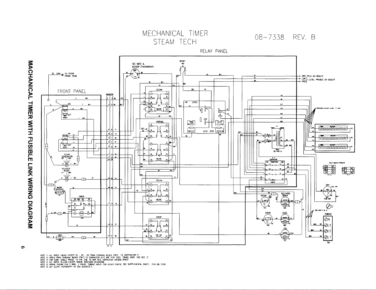
Wiring Diagram Mechanical Timer, Fusible Link 6
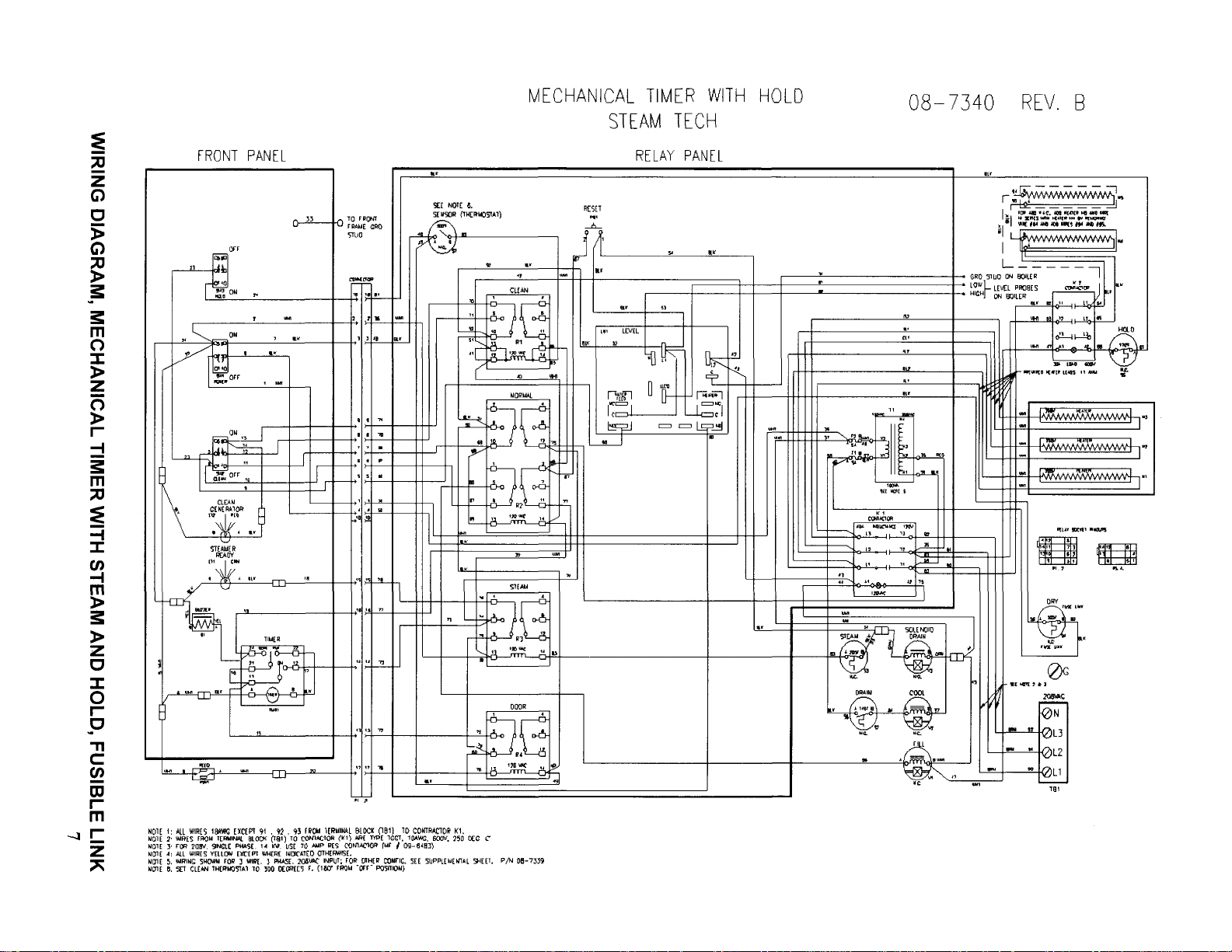
Wiring Diagram Mechanical Timer with Hold, Fusible Link 7
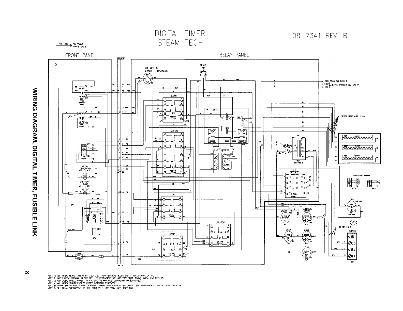
Wiring Diagram, Digital Timer, Fusible Link 8
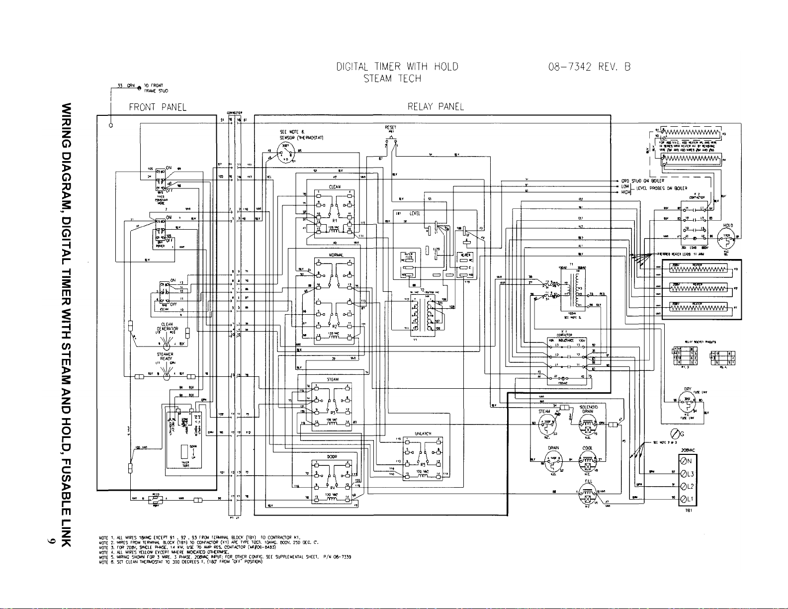
Wiring Diagram, Digital Timer with Hold, Fusible Link 9
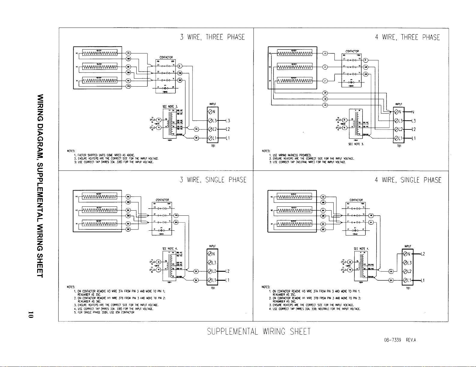
Wiring Diagram, Supplamental Wiring Sheet 1
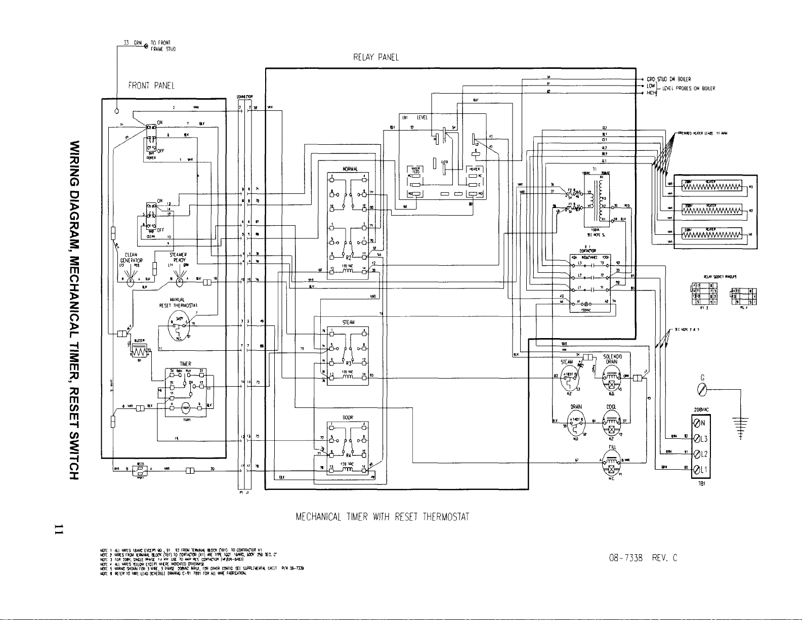
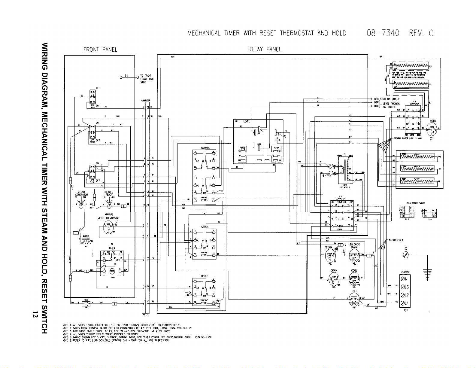
Wiring Diagram, Mechanical Timer, Reset Switch 1
Wiring Diagram, Mechanical Timer with Hold, Reset Switch 1
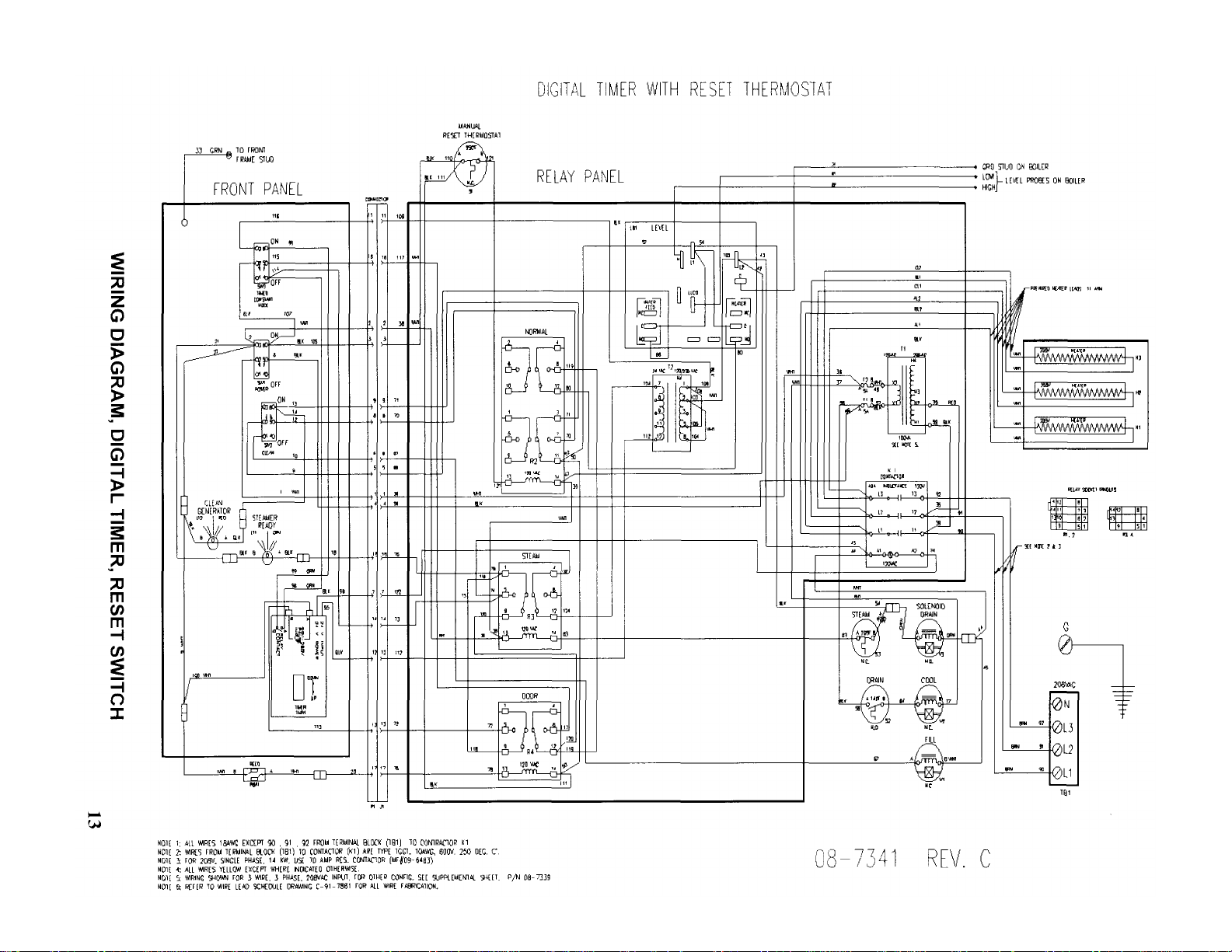
Wiring Diagram, Digital Timer, Reset Switch 1
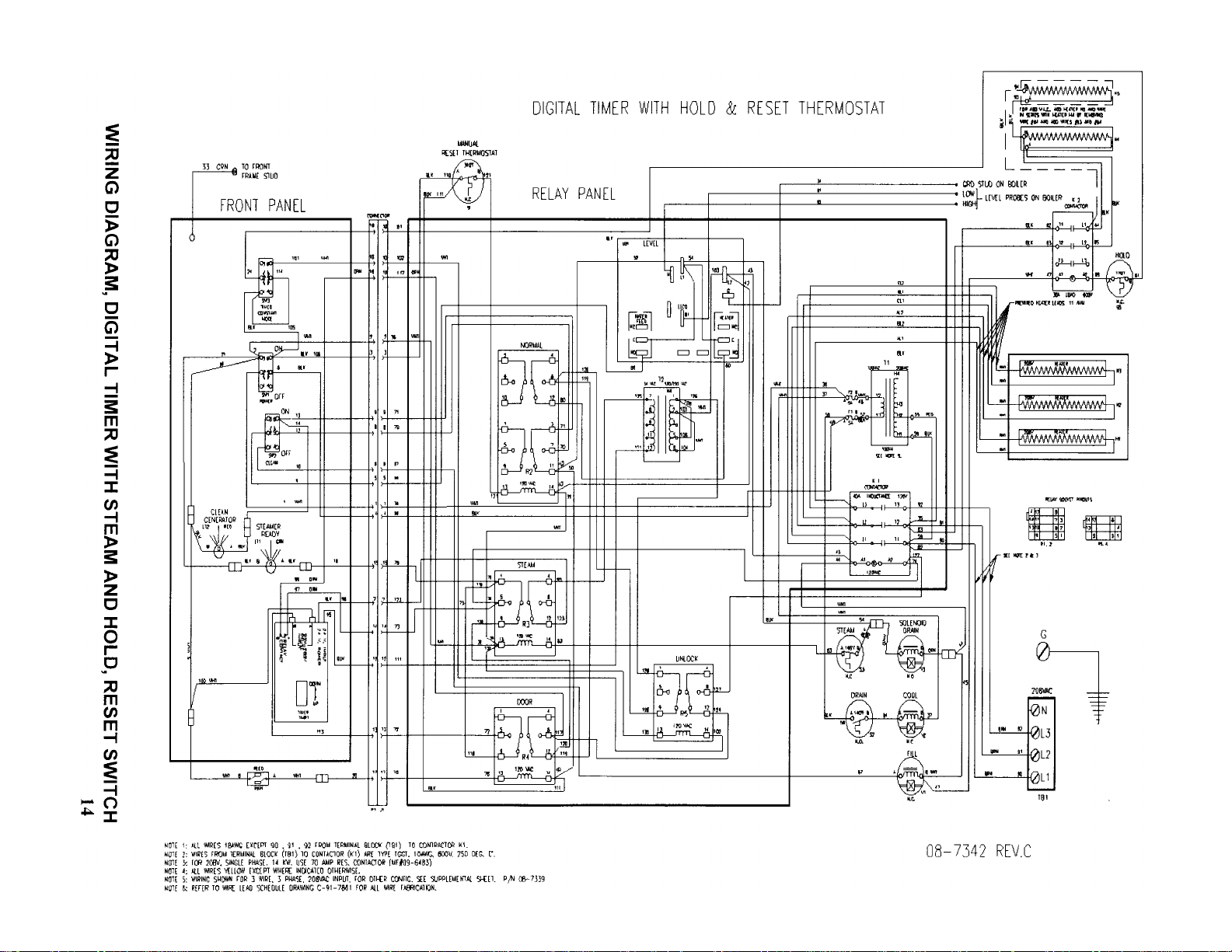
Wiring Diagram Digital Timer with Hold Reset Switch 1
3.0 INITIAL SYSTEM INSPECTION 1
3.1 General 1
3.2 Warm-up 1
3.3 Timed Steam Mode 1
3.4 Constant Steam Mode 1
3.5 Optional Steam and Hold Mode 1
3.6 Optional Digital Control Timer 1
3.7 Shut Down 1
4.0 OPERATION 1
4.1 Controls and Indicators 1
4.2 Operating Procedures 1
4.2.1 Start-up and Preheating 7
4.2.2 Cooking - Mechanical Controls 7
4.2.3 Cooking - Use of the Digital Timer 1
4.2.4 Shut -down 1
4.3 Daily Cleaning 1
4.4 Prolonged Shutdown and Cleaning 1
4.5 Generator Cleaning 1
Control Panel Mechanical Timer 2
Control Panel Mechanical Timer With Hold 2
Control Panel Digital Timer 2
Control Panel Digital Timer With Hold 2

5.0 PRINCIPLES OF OPERATION 24
5.1 General 24
5.2 Fill/Cold Water Inlet 24
5.3 Preheating and Standby 24
5.4 Steam Generation 24
5.5 Hold Feature (Option) 25
5.6 Drainage 25
5.6 1 Cooking Compartment Drainage 25
5.6.2 Drip/Spill Trough Drainage 26
5.6.3 Steam Generator Drainage 26
6.0 TROUBLESHOOTING 27
6.1 General 27
6.2 Water Level Control Board 27
6.2.1 Testing the Water Fill Relay 29
6.2.2 Testing the Low Water Relay 30
7.0 MAINTENANCE 31
7.1 General 31
7.2 Daily Cleaning 31
7.3 Preventive Maintenance 31
7.4 Cleaning the Generator 31
7.4.1 Cleaning Instructions 32
7.5 Control Panel Electrical Service Access 32
7.7 Door Adjustment 33
7.7.7 Door Alignment 33
7.7.2 Door Latch Tension Adjustment 34
7.7.3 Door Handle Tension Adjustment 34
7.8 Door Gasket Replacement 34
7.9 Solenoid Fill Valve Strainer Screen Cleaning 34
STE Top Assembly Part List 35
STE Top Assembly 36
Boiler Assembly Part List 37
Boiler Assembly 38
Door Assembly Part List 39
Door Assembly 40
Electric Plate Assembly Part List 41
Electric Plate Assembly 42
Mechanical Control Panel Assembly Part List 43
Mechanical Control Panel Assembly 44
Mechanical Control Panel With Hold Assembly Part List 45
Mechanical Control Panel With Hold Assembly 46
Digital Control Panel Assembly Part List 47
Digital Control Panel Assembly 48
Plumbing Assembly Part List 49
Plumbing Assembly 50
ii

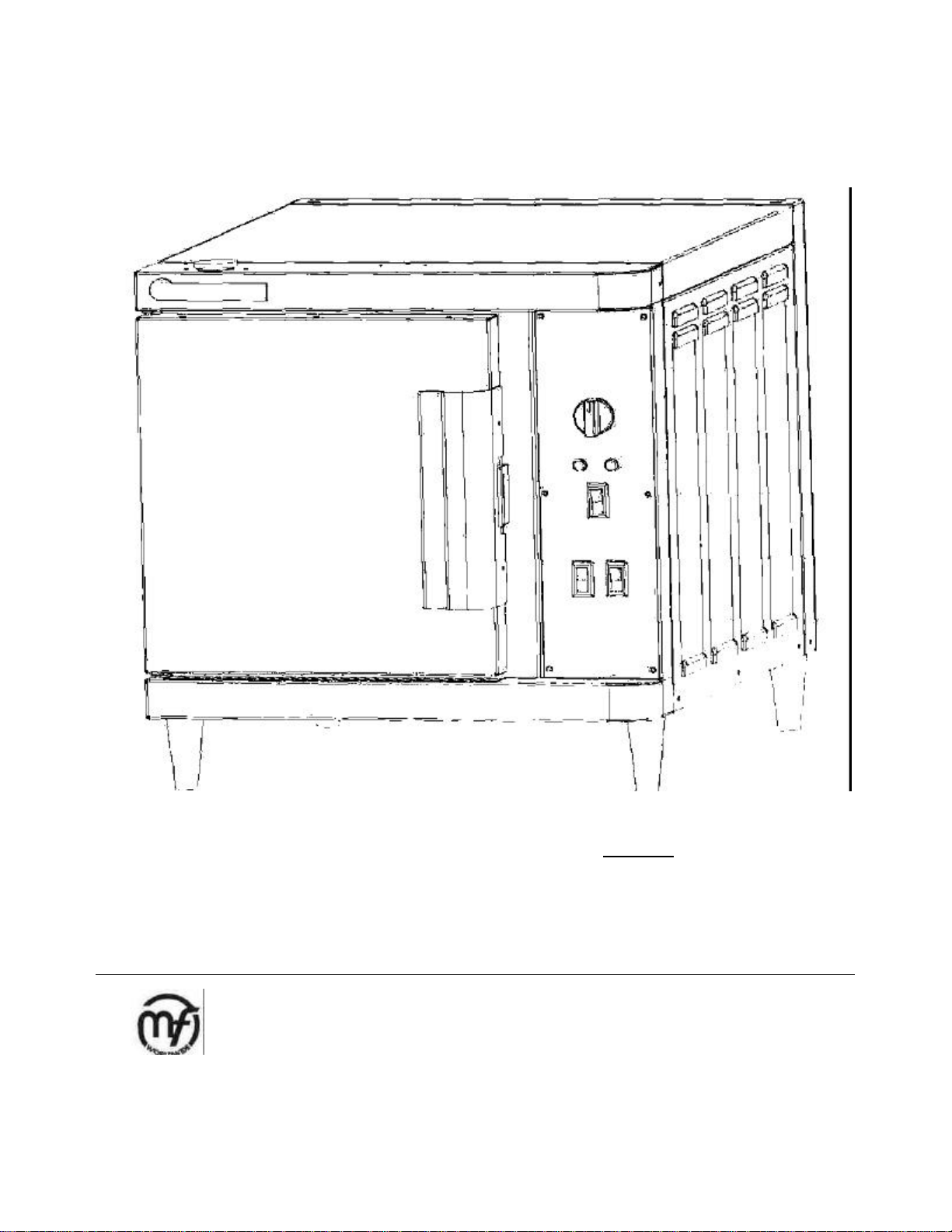
1.1 Description
The Steam Tech™ represents the latest in
counter top steam technology, designed to
apply the benefits of steam cooking to
today's health-conscious menus. Ideal for
batch cooking, a-la-carte and
rethermalization of individual entrees, the
Steam Tech™ puts the power of steam on
your countertop. The Steam Tech™ is a
pressureless steam cooker consisting of:
• 3-, 4-, or 5-pan cavity
• Electric pressureless generator (9,10,or
14kW inputs)
• Controls - mechanical or electronic
• Cleaning indicator
• Optional hold feature
These features and functions will be
discussed in greater detail in Sections 3.
A "clean generator" light indicates when it's
time to de-lime. Generators can be easily
cleaned from the outside of the cooking
compartment, through a port on top (Some
models may have an inside port).
A "close-coupled" steam generator system
gives quick start -ups and efficient steam
transfer to the cooking compartment,
without the use of fans or expensive blower
motors. In tests for energy efficiency and
cooking times performed in accordance with
ASTM standards, the Steam Tech™ yielded
impressive results over other similar counter
top steamers.
With an optional "hold" feature, your Steam
Tech™ will keep cooked foods at 160°F
until you are ready to serve, giving you
more time between cooking and serving -
it's a Market Forge exclusive.
As your operation grows, so does your
Steam Tech™. By stacking multiple
Steam Tech™ models, you can accommodate
up to 10 pans, creating a complete high-output
steam cooking system.
1.2 Basic Functioning
To begin operation, the power switch is
pressed into the on position, illuminating the
power light. This opens the water feed
solenoid valves to the steam generator. Once
the appropriate water levels have been
reached, the heating element is energized.
When the water in the steam generator has
reached 195°F, the green ready light, is
illuminated, indicating that the unit is now
ready to make steam and all controls are
functional.
A steaming mode is selected, with the timer/
selector switch.
For continuous steam, set the selector timer
knob to the "constant steam" position (the
green area of the selector/timer switch). The
cooker will continue to steam until the switch is
moved to the "off' position.
If you desire a timed steam cooking cycle, just
set the timer knob to the cook time (up to 60
minutes).
In the timed steam mode, the cooker will
create steam for the duration of time you have
set. Once the timer reaches the end of its cycle
(0 minutes) the buzzer will sound. The buzzer
is silenced by returning the timer knob to the
"off' position, which ceases the steaming
function. The generator will continue to idle at .
For units equipped with the optional
digital timer, please refer to section 3.6 for
basic explanation.
1

For units equipped with the optional steam
and hold feature, an additional mode
selector switch is used to place the cooker
into the hold mode. At the completion of
the cooking cycle, place the timer knob to
the "off position and then place the hold
switch to the "on" position. When in the
"hold" mode, the auxiliary thermostatically
controlled electric strip heater is activated.
The strip heater is mounted onto the
outside back wall of the cooking
compartment and will maintain safe
internal holding temperature (minimum of
160°F). The hold feature is controlled by a
separate thermostat with an additional
temperature gauge mounted just above
the control panel. The unit will now act as
a holding cabinet until you call for steam
again. During this time, the generator will
continue to idle at 195 °F.
Your new cooker is equipped with a clean
generator light which automatically
illuminates when the steam generator has
accumulated mineral build-up). When the
red light is "on", indicating that the heating
element has reached a point where it is
not safe to operate the steamer without
cleaning the generator and electric
heaters. To prevent heater burn-out, the
steam generator must be cleaned. The
red light tells the operator that he/she can
continue to cook until the power switch is
turned off at the end of the day. On the
next start, the unit must be cleaned (see
Section 4.5) or it will not operate.
Steam or hot water leaving the unit is drained out
the rear of the cooking cavity. Your unit is equipped
with a drain wa ter cooling system which adds cold
water to this discharge. The cold water cools the
hot discharge below 140°F which is suitable for
standard drain lines. (Note: Do not use PVC or
CPVC for drain piping.)
1.3 Service
Required service, both preventative and corrective,
is explained in Section 6. Should repairs be
required, a network of Authorized Agencies is
available to assist with prompt service. A current
Directory of Authorized Service Agencies may be
obtained by contacting:
Product Service Department Market Forge
Industries, Inc. 35 Garvey Street
Everett, Massachusetts 02149 Telephone:
(617)387-4100
The Model and Serial Numbers must be referenced
when corresponding with Market Forge. The data
plate containing the serial number is located on the
top front of the steamer (body panel).
2

2.1 Assembly
Volts AC
ST-3E ST-4E ST-5E
1- 3
- 1- 3
- 1- 3
-
PH
PH PH
PH PH
PH
The assembled Steam Tech™ Pressureless
Steam Cooker is shipped in a carton on a
skid. Steps required for assembly are as
follows:
1. Remove the carton and the unit off the
skid.
2. Install the feet into the threaded mount ing
locations on the bottom of the unit.
3. Mount the left and right pan support racks
on the mounting brackets located inside
each of the cooking compart ments.
2.2 Setting in Place
If possible, a location should be selected
under an exhaust hood which will remove
small amounts of vapor emitted from the
cooker during normal operation. Next, level
the unit after it is placed in its final location.
This is accomplished by turning the bottom
part of the adjustable feet. Using the cabinet
top as a reference, obtain level adjus tment
left-to-right and front -to-back.
2.3 Service Connections
Service connections that are made at the back
of the cooker, include cold water inlet, drain,
and electrical. Please see the illustrations and
table located in Table 2.1 for service
connections, details and dimensions.
2.3.1 Water Connections
Before connecting water to this unit, have
water supply analyzed to make sure that
hardness is no greater than 2.0 grains per
gallon and pH level is within the range of 7.0-
8.5. Water which fails to meet these standards
should be treated by the installation of a water
conditioner.
EQUIPMENT FAILURE CAUSED BY INADEQUATE
WATER QUALITY IS NOT COVERED UNDER WAR-
RANTY.
Caution: Do not use PVC or CPVC piping for inlet
water service connections.
Please refer to Table 2.1 for details and locations of
water and drain connections.
2.3.2 Electrical Connections
Caution: Use copper wire only for power supply
connections.
Please refer to Table 2.1 for details of electrical service
connections.
Electrical Characteristics
Electrical connection power supply should utilize wire
suitable for 90°C.
(9kW)
208 (197- 41A 24A 46A 26A 64A 37A
219) 46A 26A 51A 29A 71A 41A
240 (220- 34A 20A 38A 22A 53A 31A
240) 38A 22A 42A 24A 58A 34A
480 (360- 19A 11A 21A 12A 29A 17A
500)
220/380
3-phase
4 wire
240/415
3-phase
4 wire
11A
13A
(10kW)
13A
14A
(14kW)
18A
19A
3
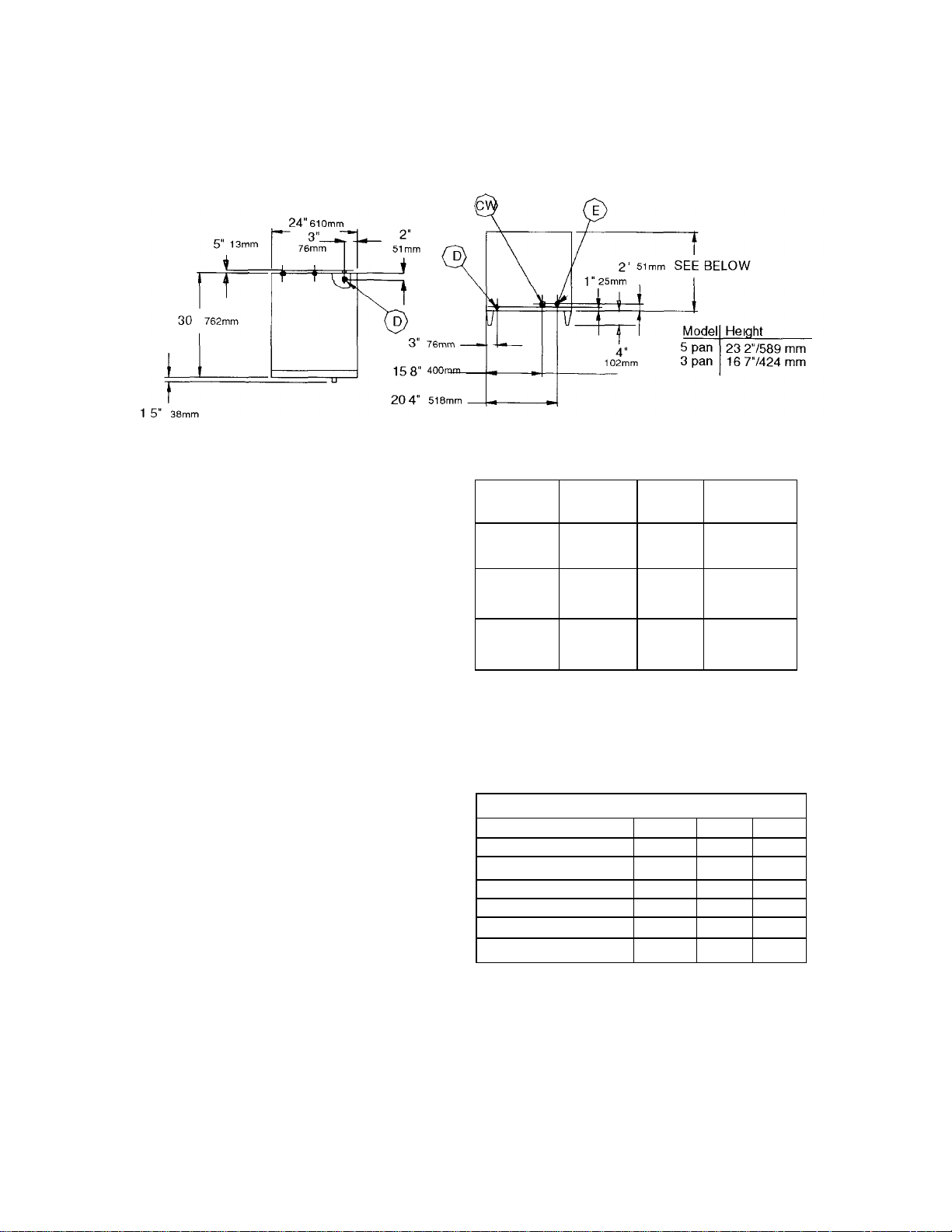
Table 2.1: Service Connections
E -Electncal Connection
CW- Cold Water Inlet
D- Drain Connection
Water Connections
Cold water 1/2" female compression fitting
water line will have maximum of 50 psi
and minimum of 25 psi of water pressure.
Drain pipe full 1" female NPT to open floor
drain with air break. Do not exceed 8' in
length and no more than 2 elbows. Before
connecting water to this unit, water supply
should be analyzed to make sure
hardness is no greater than 2.0 grains per
gallon and pH level is within the range of
7.0-8.5. Water which fails to meet these
standards should be treated by
installation of a water conditioner.
Equipment failure caused by
inadequate water quality is not covered
under warranty.
Internal Dimensions
Model Height Width Depth
ST-3E
ST-4E
ST-5E
107" 271
mm
1395" 354
mm
172" 436
mm
14" 356
mm
14" 356
mm
14" 356
mm
225" 571 mm
225" 571 mm
225" 571 mm
Capacity
Pan Size Number of Pans
ST-3E ST-4E ST-5E
12"X20"X1" 6 7 8
12"x20"x2 1/2" 3 4 5
12"X20"X4" 2 3 4
GN 1/1 25mm deep 6 7 8
GN 1/1 65mm deep 3 4 5
GN 1/1 100mm deep 2 3 4
4

2.4 Reversing the Doors
The Steam Tech™ Pressureless Steam
Cooker has a reversible cooking compart ment door for your convenience. This section
contains instructions for reversing this door.
1. Opening the cooking compartment door
2. Remove the two screws that attach the
top hinge to the front of the unit.
3. Slide the door upwards, off the bottom
hinge.
4. Remove the two screws that attach the
bottom hinge to the front of the units.
5. Remove the plastic hole plugs from the
front of the unit. Push the black hole
plugs into the left upper and lower hinge
mounting holes.
6. Reinstall the top hinge with spacers and
screws into the right lower hinge mount ing holes. Rotate the hinge 180° for
installation, so that the pin which the
door rides on is now facing up. The hinge
must be rotated because it will now
function as the bottom hinge. DO NOT
COMPLETELY TIGHTEN THE HINGE
MOUNTING SCREWS YET. These will
be used later for adjusting the door.
7. Remove the door latch assembly from the
face of the unit. The 2 nuts mounting the
door latch are located behind the face of
the unit and must be accessed by
removing the control panel. Remove the
control panel by unscrewing the six
mounting screws and pulling the panel
away from the front frame.
8. Remove the two white hole plugs from
the left door latch mounting holes, and
insert them into the right door latch
mounting holes (where the door latch
assembly was originally mounted).
9. Rotate the door latch assembly 180°,
and install into the left door lat ch mounting
holes.
NOTE: Each stud on the latch assembly
should have a plastic washer, a spring, a
plastic washer and a Nyloc type nut,
10. To adjust the tension of the door latch,
tighten both nuts down until the springs are
fully compressed, then back each nut off
1/2 turn.
11. Replace the control panel.
12. Remove the inner door panel by removing the six screws and spacers on the top
and bottom of the door.
13. Move the magnet and magnet clip to
the opposite side of the inner door panel
(REF Fig.7.3).
14. Put the door back together, making sure
the magnet is located at the top of the door,
and refasten it together with the six screws
and spacers, into the top and bottom of the
door.
15. Rotate the door 180° for mounting.
16. Slide the remaining hinge into the top
door bearing.
17. Slide the door and hinge assembly
down onto the hinge which you have
already mounted to the front of the unit.
Use the two to mount the top hinge into the
right upper hinge mounting holes. DO NOT
COMPLETELY TIGHTEN THE HINGE
MOUNTING SCREWS YET. These will be
used later for adjusting the door.
NOTE: Be sure to include spacer washers
behind hinges.
18. Door adjustment is covered in Section
7.7 of this manual.
5
 Loading...