

Page 1
ST-10 SERIES
10 PAN CONVECTION STEAMERS
INSTALLATION - OPERATION - MAINTENANCE
MODELS
ST-10M24E
ST-10M36E
ST-10M24G
ST-10M36G
ST-10M24D
ST-10M36D
44 Lakeside Avenue, Burlington, Vermont 05401 USA
Telephone: (802) 658-6600 Fax: (802) 864-0183
www.mi.com PN 14-0272 Rev D (4/16)
© 2016 - Market Forge Industries Inc.
Page 2

Your Service Agency’s Address:
Model
Serial number
Steamer installed by
Installation checked by
Page 3

IMPORTANT
TABLE OF CONTENTS
WARNING: Improper installation, adjustment, alternation,
service or maintenance can
cause property damage, injury or death. Read the installation, operation and maintenance instructions thoroughly
before installing or servicing
this equipment.
INSTRUCTIONS TO BE FOLLOWED IN THE EVENT THE
USER SMELLS GAS MUST BE
POSTED IN A PROMINENT LOCATION. This information may
be obtained by contacting your
local gas supplier.
FOR YOUR SAFETY
Do not store or use gasoline or
other ammable vapors or liquids in the vicinity of this or any
other appliance.
The information contained in this
manual is important for the proper installation, use, and maintenance of this steamer. Adherence to these procedures and
instructions will result in satisfactory baking results and long,
trouble free service. Please
read this manual carefully and
retain it for future reference.
INSTALLATION
Introduction .............................................................. 2
Service Connections ..................................................... 3
Installation............................................................... 9
Assembly ............................................................ 9
Setting in Place ...................................................... 9
Mechanical Connections .............................................. 9
Water Connections ................................................... 9
Installation Checkout ................................................. 9
Initial Control Settings ................................................ 9
Cooker Checkout .................................................... 10
Shut Down Procedure ............................................... 10
Reversing the Doors ................................................. 10
PRV – Pressure Reducing Valve Maintenance and Adjustments ............. 12
OPERATION
Operating Procedures ................................................... 13
Manual Control Panel ................................................... 14
Digital Control Panel .................................................... 15
Test Kitchen Bulletin ..................................................... 16
Suggested Steam Times ................................................. 17
MAINTENANCE
Cleaning & Preventative Maintenance..................................... 19
ERRORS: Descriptive, typographic or pictorial errors are
subject to correction. Specications are subject to change
without notice.
Page 4

Introduction
DESCRIPTION
The ST-10 is a pressureless steam cooker consisting of
two independently controlled compartments enclosed in
a single cabinet. Each compartment is equipped with a
separate three-piece door with inner gasket plate isolated from the exterior surface. Door latches operate by
slam action for positive sealing of inner door. Steam and
steam-condensing circuits are electrically controlled. Operating controls are displayed on a single front-mounted
panel and include separate timers with indicator lights for
selection of constant steam or 60-minute-long duration
cooking.
A separate steam source required for operation of the
Pressureless Cooker is normally purchased with it, please
refer to the respective manual for guidance.
BASIC FUNCTIONING
The Model ST-10 may be operated with only one compartment in use; or both may be used simultaneously. Each
compartment is equipped with identical controls, allowing
selection of constant steam or 60-minute timer operation.
The cooker becomes operational when it is set to constant steam, or the timer is set at the desired cooking time
and the compartment door is closed. The indicator light
comes on and the steam solenoid valve opens, allowing
steam to ow into the compartment.
When steam owing inside the compartment has raised
the interior temperature to 195°F, the contacts of a thermostatic switch automatically close, completing the circuit
to the timer motor and starting the cooking time period. At
the end of the set interval, timer contacts switch to shut
off the cooking operation and sound a signal buzzer. The
buzzer is silenced by returning the timer dial to the OFF
position. In the constant steam mode, operation will be
continuous.
Steam emitted from the compartment along with liquid
cooking drainage is directed through a drain screen inside
the compartment into the cooker drain line. A cold water
solenoid valve connected into the cooker drain line is automatically actuated by a thermostatic switch in the boiler
drain to condense the steam to water prior to discharge
into the boiler drain.
SERVICE
Required service, both preventive and corrective, is explained in Section 6. Should repairs be required, a net-
work of authorized agencies is available to assist with
prompt service. A current Directory of Authorized
Service Agencies may be obtained by contacting:
Market Forge
44 Lakeside Avenue, Burlington, VT 05401
802-658-6600
www.mi.com
The model and serial numbers must be referenced when
corresponding with Market Forge. The data plate containing the serial number pertaining to the equipment is located on the lower front trim of the cabinet.
INSTALLATION
2
Page 5
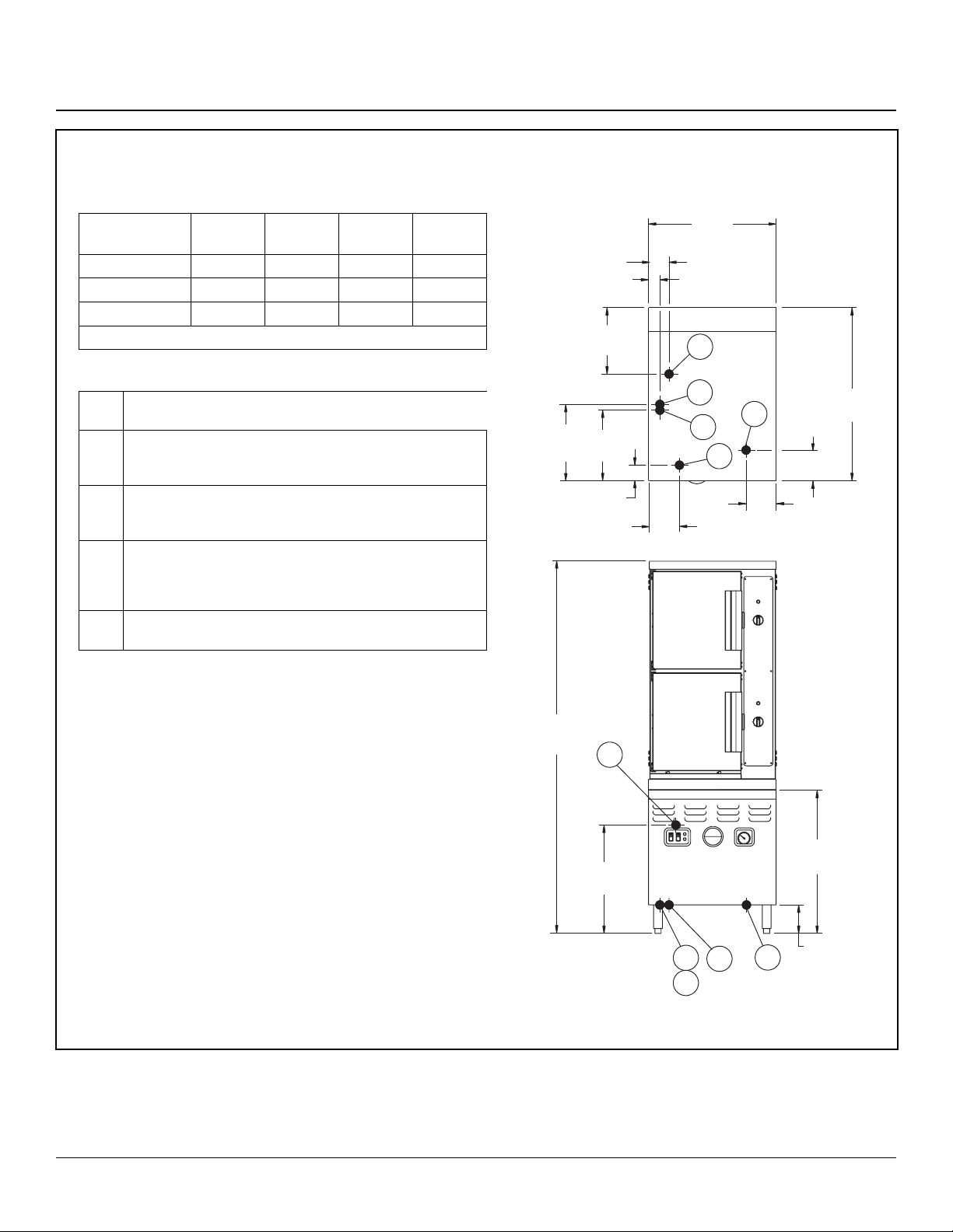
ST-10M24E
Service Connections
ELECTRICAL REQUIREMENTS
24kW
3pH
208 (197-219) 66 100 117 --
240 (220-240) 58 87 -- 116
480 (360-500) 29 44 -- 58
Details of other electrical systems available upon request.
36kW
3pH
42kW
3pH
48kW
3pH
SERVICE CONNECTIONS
EP Electrical Connection - Use wire suitable for at least 90°C.
Nominal amp per line wire.
CW1 Cold Water - 3/8” (10mm) NPT for cold water to boiler. Cold
water lines will have a maximum of 50 PSI (3.5kg/cw2) and a
minimum of 25 PSI (1.8 kg/cw2) water pressure
CW2 Cold Water - 3/8” (10mm) NPT for cold water to condenser.
Cold water lines will have a maximum of 50 PSI (3.5kg/cw2)
and a minimum of 25 PSI (1.8 kg/cw2) water pressure.
D Drain - Pipe full 2” (50mm) NPT to flush floor drain capable
of receiving water flowing at a maximum rate of 5 gallons (19
liters) per minute. DO NOT MAKE SOLID CONNECTION TO
FLOOR DRAIN.
ST Steam Take-off - Connection for operation of adjacent steam
powered equipment.
DIMENSIONS ARE IN INCHES [MM]
4 [102]
2.5 [64]
10.5
[267]
CW1
12.5
10.5
[318]
[267]
3 [76]
5 [127]
24 [610]
D
CW2
6 [152]
33
EP
ST
[838]
6 [152]
OPERATION WILL BE BY:
Electrically powered, A.S.M.E. constructed and National Board
Registered, 15 PSI (1 kg/cm2) steam boiler rated at 24kW, additional
ratings available as an option
NOTE: The only available space to supply utilities to the boiler is the 6”
(152mm) space between the floor and the cabinet base. PVC & CPVC
Pipe are not acceptable materials for drains.
CAUTION: REMOTE KETTLE OPERATION If this boiler is feeding a
remote kettle that will be more than 5 feet (1.5 meters) away, consult
factory before ordering.
WATER SUPPLY
Good quality water feed is the responsibility of the owner. Water quality
must be within the following general guidelines.
TDS: 40-125 ppm Hardness: 35-100 ppm Chlorine: <0.2 ppm
Silica: <13 ppm Chlorides: <25 ppm
Chloramine: <0.2 ppm pH: 7.0 - 8.5
The best defense against poor water quality is a water treatment system
designed to meet your water quality conditions.
Figure 1
69.25
[1759]
22
[559]
ST
28
[711]
6 [152]
CW1
CW2
EP
D
3
INSTALLATION
Page 6
Service Connections
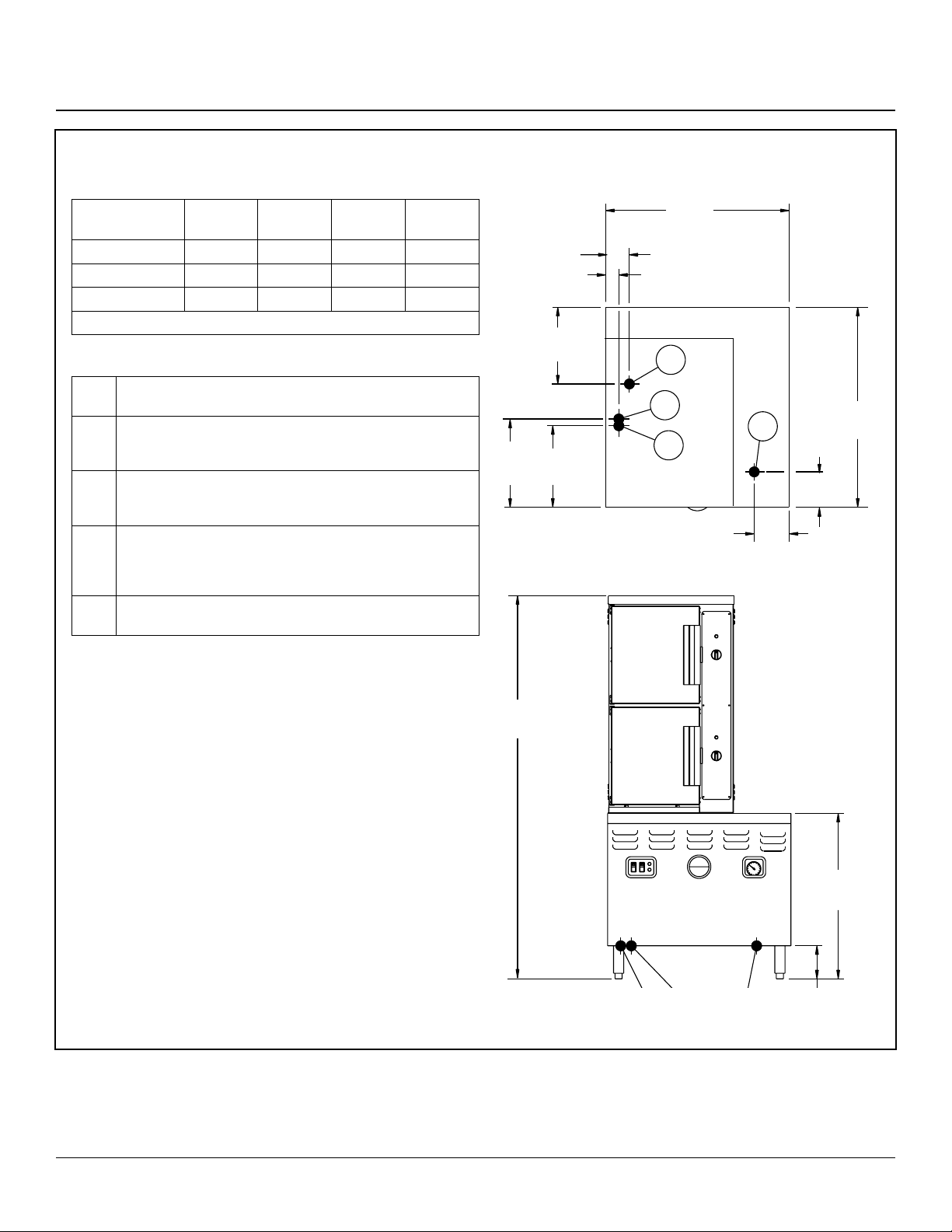
ST-10M36E
ELECTRICAL REQUIREMENTS
24kW
3pH
208 (197-219) 66 100 117 --
240 (220-240) 58 87 -- 116
480 (360-500) 29 44 -- 58
Details of other electrical systems available upon request.
36kW
3pH
42kW
3pH
48kW
3pH
SERVICE CONNECTIONS
EP Power Supply - Use wire suitable for at least 90°C. Nominal
amp per line wire:
CW1 Cold Water - 3/8” (10mm) NPT for cold water to boiler. Cold
water lines will have a maximum of 50 PSI (3.5kg/cw2) and a
minimum of 25 PSI (1.8 kg/cw2) water pressure
CW2 Cold Water - 3/8” (10mm) NPT for cold water to condenser.
Cold water lines will have a maximum of 50 PSI (3.5kg/cw2)
and a minimum of 25 PSI (1.8 kg/cw2) water pressure.
D Drain - Pipe full 2” (50mm) NPT to flush floor drain capable
of receiving water flowing at a maximum rate of 5 gallons (19
liters) per minute. DO NOT MAKE SOLID CONNECTION TO
FLOOR DRAIN.
ST Steam Take-off - Connection for operation of adjacent steam
powered equipment.
DIMENSIONS ARE IN INCHES [MM]
4 [102]
2.5 [64]
10.5
12.5
[318]
[267]
10.5
[267]
D
CW1
CW2
36 [914]
6 [152]
EP
33
[838]
6 [152]
OPERATION WILL BE BY:
Electrically powered, A.S.M.E. constructed and National Board Registered,
15 PSI (1 kg/cm2) steam boiler rated at
24kW
NOTE: The only available space to supply utilities to the boiler is the 6”
(152mm) space between the floor and the cabinet base. PVC & CPVC
Pipe are not acceptable materials for drains.
CAUTION: REMOTE KETTLE OPERATION If this boiler is feeding a
remote kettle that will be more than 5 feet (1.5 meters) away, consult
factory before ordering.
WATER SUPPLY
Good quality water feed is the responsibility of the owner. Water quality
must be within the following general guidelines.
TDS: 40-125 ppm Hardness: 35-100 ppm Chlorine: <0.2 ppm
Silica: <13 ppm Chlorides: <25 ppm
Chloramine: <0.2 ppm pH: 7.0 - 8.5
The best defense against poor water quality is a water treatment system
designed to meet your water quality conditions.
Figure 2
69.25
[1759]
28
[711]
INSTALLATION
4
Page 7
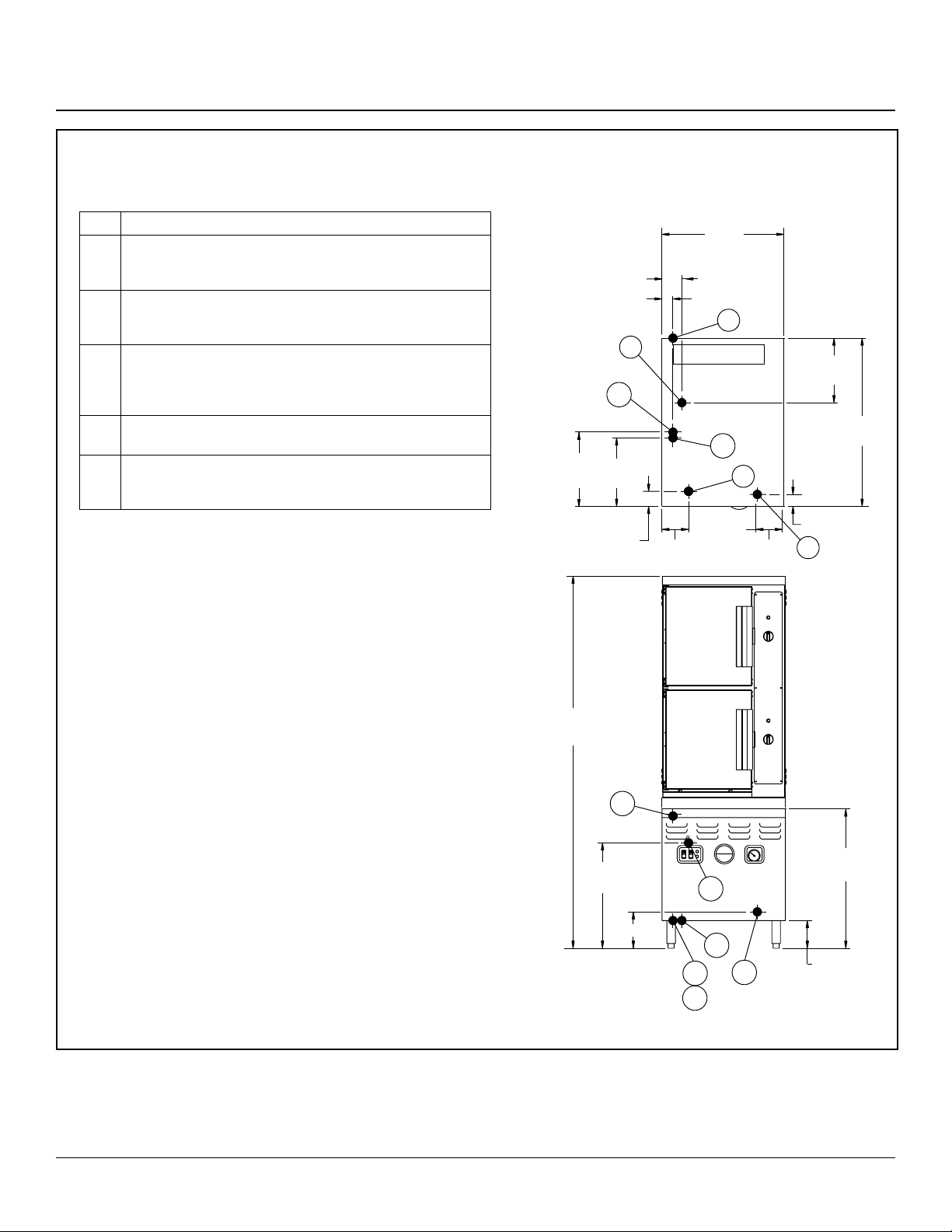
ST-10M24G
Service Connections
SERVICE CONNECTIONS
G Gas Connection - 3/4” (19mm) NPT, 200,000 BTU
CW1 Cold Water - 3/8” (10mm) NPT for cold water to boiler. Cold
water lines will have a maximum of 50 PSI (3.5kg/cw2) and a
minimum of 25 PSI (1.8 kg/cw2) water pressure.
CW2 Cold Water - 3/8” (10mm) NPT for cold water to condenser.
Cold water lines will have a maximum of 50 PSI (3.5kg/cw2) and
a minimum of 25 PSI (1.8 kg/cw2) water pressure.
D Drain - Pipe full 2” (50mm) NPT to flush floor drain capable
of receiving water flowing at a maximum rate of 5 gallons (19
liters) per minute. DO NOT MAKE SOLID CONNECTION TO
FLOOR DRAIN.
EC Electrical Connection - 120 Volts AC, 60 Hz, single phase,
and a 9 foot Power Cord/NEMA 5-15.
ST Steam Take-off - Connection for operations of adjacent steam
powered equipment. Requires steam take-off kit (optional at
extra cost).
OPERATION WILL BE BY
Gas fired, A.S.M.E. constructed and National Board Registered, 15PSI (1
kg/cm2) steam boiler rated at 200,000 BTU
Notes: If equipment is installed where elevation exceeds 2,000 feet
(609.6 meters) above sea level, specify installation altitude so that proper
gas orifices can be provided.
The only available space to supply utilities to the gas boiler is the 6”
(152mm) space between the floor and the cabinet.
Allow 3” (76mm) space from side wall and 6” (152mm) from rear wall if
adjoining walls are combustible.
PVC & CPVC PIPE ARE NOT ACCEPTABLE MATERIALS FOR
DRAINS.
CAUTION: REMOTE KETTLE OPERATION If this boiler is feeding a
remote kettle that will be more than 5 feet (1.5 meters) away, consult
factory before ordering.
DIMENSIONS ARE IN INCHES [MM]
4[102]
2.5 [64]
D
CW1
12.5
10.5
[318
[267]
3 [76]
69.25
[1759]
5 [127]
EC
24 [610]
EC
FLUE
CW2
ST
5 [127]
10.5
[267]
33
[838]
2.75 [70]
G
WATER SUPPLY
Good quality water feed is the responsibility of the owner. Water quality
must be within the following general guidelines.
TDS: 40-125 ppm Hardness: 35-100 ppm Chlorine: <0.2 ppm
Silica: <13 ppm Chlorides: <25 ppm
Chloramine: <0.2 ppm pH: 7.0 - 8.5
The best defense against poor water quality is a water treatment system
designed to meet your water quality conditions.
Figure 3
5
22
[559]
8 [203]
CW1
CW2
28
[711]
ST
D
G
6 [152]
INSTALLATION
Page 8

Service Connections
SERVICE CONNECTIONS
ST-10M36G
G Gas Connection - 3/4” (19mm) N.P.T. female for 200,000 BTU
boiler.
G1 Gas Connection - 1” (25mm) N.P.T. female for 300,000 BTU boiler.
CW1 Cold Water - 3/8” (10mm) NPT for cold water to boiler. Cold water
lines will have a maximum of 50 PSI (3.5kg/cw2) and a minimum
of 25 PSI (1.8 kg/cw2) water pressure.
CW2 Cold Water - 3/8” (10mm) NPT for cold water to condenser. Cold
water lines will have a maximum of 50 PSI (3.5kg/cw2) and a minimum of 25 PSI (1.8 kg/cw2) water pressure.
D Drain - Pipe full 2” (50mm) NPT to flush floor drain capable of
receiving water flowing at a maximum rate of 5 gallons (19 liters)
per minute. DO NOT MAKE SOLID CONNECTION TO FLOOR
DRAIN.
EC Electrical Connection - 120 Volts AC, 60 Hz, single phase, and
a 9 foot Power Cord/NEMA 5-15.
ST Steam Take-off - Connection for operations of adjacent steam
powered equipment. Requires steam take-off kit (optional at extra
cost).
OPERATION WILL BE BY
Gas fired, A.S.M.E. constructed and National Board Registered, 15 PSI (1
kg/cm2) steam boiler rated at 200,000 BTU
Notes: If equipment is installed where elevation exceeds 2,000 feet (609.6
meters) above sea level, specify installation altitude so that proper gas orifices can be provided.
The only available space to supply utilities to the gas boiler is the 6” (152mm)
space between the floor and the cabinet.
Allow 3” (76mm) space from side wall and 6” (152mm) from rear wall if adjoining walls are combustible.
PVC & CPVC PIPE ARE NOT ACCEPTABLE MATERIALS FOR DRAINS.
CAUTION: REMOTE KETTLE OPERATION If this boiler is feeding a remote
kettle that will be more than 5 feet (1.5 meters) away, consult factory before
ordering.
WATER SUPPLY
Good quality water feed is the responsibility of the owner. Water quality must
be within the following general guidelines.
TDS: 40-125 ppm Hardness: 35-100 ppm Chlorine: <0.2 ppm
Silica: <13 ppm Chlorides: <25 ppm
Chloramine: <0.2 ppm pH: 7.0 - 8.5
The best defense against poor water quality is a water treatment system
designed to meet your water quality conditions.
DIMENSIONS ARE IN INCHES [MM]
4[102]
2.5 [64]
D
CW1
12.5
10.5
[318
[267]
5 [127]
CW1
CW2
69.25
[1759]
3 [76]
EC
ST
22
[559]
8 [203]
CW2
36 [914]
EC
FLUE
ST
D
5 [127]
G
G1
10.5
[267]
2.75 [70]
G
6 [152]
33
[838]
G1
27
[686]
28
[711]
INSTALLATION
Figure 4
6
Page 9

ST-10M24D
Service Connections
SERVICE CONNECTIONS
EC Electrical Connection - 120 Volts AC, 60 Hz, single
phase, and a 9 foot Power Cord/NEMA 5-15.
CR Condensate Return - 1/2” (13mm) N.P.T. female from
ball float trap may be connected to condensate return
line (optional at extra cost).
CW Cold Water - 3/8” (10mm) NPT for cold water to con-
denser. Cold water line will have a maximum of 50 PSI
(3.5kg/cw2) and a minimum of 25 PSI (1.8 kg/cw2)
water pressure.
D Drain - Pipe full 2” (50mm) NPT to flush floor drain
capable of receiving water flowing at a maximum rate of
5 gallons (19 liters) per minute. DO NOT MAKE SOLID
CONNECTION TO FLOOR DRAIN.
S Steam Supply - Minimum BHP required: 3.0 BHP at a
minimum pressure of 15 PSI (1.0 kg/cm2). 3/4” (19mm)
NPT pressure reducing valve will reduce incoming
pressure of 20 to 50 PSI (1.3 to 3.5 kg/cm2) to required
15 PSI (1.0 kg/cm2).
NOTES: The only available space to supply utilities is the 6”
(152mm) height between the floor and the cabinet.
PVC & CPVC are not acceptable materials for drain lines.
DIMENSIONS ARE IN INCHES [MM]
24 [610]
4.3 [109]
4 [102]
2.5 [64]
2 [51]
D
10.5
[267]
EC
CR
CW
7 [177]
10.5
[267]
33
[838]
S
3 [76]
WATER SUPPLY
Good quality water feed is the responsibility of the owner. Water
quality must be within the following general guidelines.
TDS: 40-125 ppm Chlorides: <25 ppm
Silica: <13 ppm pH: 7.0 - 8.5
Chloramine: <0.2 ppm Chlorine: <0.2 ppm
Hardness: 35-100 ppm
The best defense against poor water quality is a water treatment
system designed to meet your water quality conditions.
Appliance to be installed with backflow protection according to
federal, state or local codes.
Figure 5
69.25
[1759]
EC
CW
28
[711]
S
D
17
[432]
6 [152]
7
INSTALLATION
Page 10

Service Connections
ST-10M36D
SERVICE CONNECTIONS
EC Electrical Connection - 120 Volts AC, 60 Hz, single
phase, and a 9 foot Power Cord/NEMA 5-15.
CW Cold Water - 3/8” (10mm) NPT for cold water to con-
denser. Cold water lines will have a maximum of 50
PSI (3.5kg/cw2) and a minimum of 25 PSI (1.8 kg/cw2)
water pressure.
CR Condensate Return - 1/2” (13mm) N.P.T. female from
ball float trap may be connected to condensate return
line (optional at extra cost).
D Drain - Pipe full 2” (50mm) NPT to flush floor drain
capable of receiving water flowing at a maximum rate of
5 gallons (19 liters) per minute. DO NOT MAKE SOLID
CONNECTION TO FLOOR DRAIN.
S Steam Supply - Minimum BHP required: 3.0 BHP at a
minimum pressure of 15 PSI (1.0 kg/cm2). 3/4” (19mm)
NPT pressure reducing valve will reduce incoming
pressure of 20 to 50 PSI (1.3 to 3.5 kg/cm2) to required
15 PSI (1.0 kg/cm2).
NOTES: The only available space to supply utilities is the 6”
(152mm) height between the floor and the cabinet.
PVC & CPVC are not acceptable materials for drain lines.
DIMENSIONS ARE IN INCHES [MM]
36 [914]
4.3 [109]
4 [102]
2.5 [64]
2 [51]
D
10.5
[267]
EC
CR
CW
S
17 [432]
10.5
[267]
33
[838]
3 [76]
WATER SUPPLY
Good quality water feed is the responsibility of the owner. Water
quality must be within the following general guidelines.
TDS: 40-125 ppm Chlorides: <25 ppm
Silica: <13 ppm pH: 7.0 - 8.5
Chloramine: <0.2 ppm Chlorine: <0.2 ppm
Hardness: 35-100 ppm
The best defense against poor water quality is a water treatment
system designed to meet your water quality conditions.
Appliance to be installed with backflow protection according to
federal, state or local codes.
Figure 6
69.25
[1759]
EC
CW
28
[711]
S
D
17
[432]
6 [152]
INSTALLATION
8
Page 11

Installation
ASSEMBLY
The Pressureless Cooker is factory-mounted on a cabinet base containing either a steam boiler or direct steam
connection controls for the cooker. The assembled unit is
shipped bolted to a skid, with cabinet feet in a separate
container. Steps required for assembly are as follows:
1. Remove the four bolts that fasten the equipment
frame to the skid.
2. Install feet in threaded mounting locations of the cabinet frame.
3. Mount the two bafes on studs located on the rightinside of the cooking compartments.
4. Mount the four pan support racks in brackets inside
control compartments.
5. Attach panels to lower cabinet. Detailed instructions
are enclosed with the panels.
SETTING IN PLACE
Installation must be under an exhaust hood, which will
remove small amounts of water vapor emitted when the
cooker doors are opened, and exhaust fumes from the
air. Level the unit in nal location by turning the adjustable
feet. Using the cabinet top as a reference, obtain level
adjustment left-to-right and front-to-back.
MECHANICAL CONNECTIONS
Since the Pressureless Cooker is interconnected at the
factory to the steam boiler or direct steam plumbing, no
eld connections to the cooker are required. All electrical
and plumbing connections are routed to the steam boiler
cabinet through the 6-inch-high space between the oor
and the bottom edge of the cabinet frame.
WATER CONNECTIONS
Before connecting water to this unit, have water supply
analyzed to make sure that hardness is no grater than
2.0 grains per gallon and pH level is within the range of
7.0–8.5. Water that fails to meet these standards should
be treated by the installation of a water conditioner.
WARNING
EQUIPMENT FAILURE CAUSED BY INADEQUATE WATER QUALITY IS NOT COVERED
UNDER WARRANTY.
CAUTION
PVC or CPVC are not acceptable materials for
drains.
INSTALLATION CHECKOUT
If the cooker fails to perform as described, consult the
Trouble-Shooting Guide for corrective action. If difculty
arises with the boiler, reference the separate service and
parts manual for that equipment.
Before making this check-out, the operator must be thoroughly familiar with the operating procedures in this manual and with the function of each control described.
INITIAL CONTROL SETTINGS
Before beginning the start-up procedures for the cooker,
the instruction plate and service manual for the steam
boiler must be consulted and all start-up procedures completed to supply 15 PSI steam to the steam inlet line for
the cooker.
1. All steam boiler controls are in the operating mode
and 15 PSI steam is applied to the cooker inlet plumbing.
2. Cooker timers for both compartments are in the OFF
position.
3. Cooker compartments are empty of all information
materials, pan supports are mounted in place, and
doors are open.
9
INSTALLATION
Page 12

Installation
COOKER CHECKOUT
The cooker check-out procedures are as follows:
1. With the doors open set timers to about the “4-minute” position. Observe that indicator lights are off and
steam does not enter compartments.
2. Close cooker compartment doors. Observe that indicator lights turn on, and steam can be heard rushing
into the compartment simultaneously with the door
closing.
3. Observe the boiler drain line for passage of steam
into the open oor drain. Correct steam condenser
operation is evidenced by presence of water owing
from the drain line.
4. Observe cooker operation for several minutes. Operation is correct if timer dials begin to rotate after a
short delay period required for preheating. After the
delay period plus the “4-minute” initial setting, the timer dials will return to the “0-Minute” position, at which
a buzzer sounds. The buzzer is silenced by turning
the dial to the OFF position.
SHUT DOWN PROCEDURE
No shut-down procedure is required for the Pressureless
Cooker except to check that all timer dials (2) are in the
OFF position and the compartment doors are open. Consult the steam boiler instruction plate and complete the
shut-down procedures for the boiler.
REVERSING THE DOORS
The Pressureless Steam Cooker has a reversible cooking
compartment door. This section contains instructions for
reversing this door.
1. Turn off power to the unit.
2. Open the cooking compartment door
3. Remove the two screws that attach the top hinge to
the front of the unit.
4. Slide the door upwards, off the bottom hinge.
5. Remove the two screws that attach the bottom hinge
to the front of the units.
6. Remove the right and left side panels by unscrewing the 1 screw on each panel and sliding the panel
down.
7. Remove the door interlock assembly by unscrewing
the two nuts that hold it in place (assembly is attached
to the screws in the top right hinge mounting holes).
8. Remove the four screws in the right side hinge mounting holes and install them in the left side hinge mounting holes (where the hinges were originally mounted).
9. Using the nuts removed in step #6, reinstall the door
interlock assembly onto the 2 screws in the lower left
hinge mounting holes with by moving the assembly
over the cooking cavity to the other side of the unit.
Rotate the door interlock assembly 180° for installation, so that the switch is now facing up.
10. Reinstall the top hinge and screws into the right lower
hinge mounting holes. Rotate the hinge 180° for installation, so that the pin which the door rides on is
now facing up. The hinge must be rotated because
it will now function as the bottom hinge. DO NOT
COMPLETELY TIGHTEN THE HINGE MOUNTING
SCREWS YET. These will be used later for adjusting
the door.
11. Remove the door latch assembly from the face of the
unit. The 2 nuts mounting the door latch are located
behind the face of the unit and must be accessed
where the right side panel was removed.
12. Remove the two white hole plugs from the left door
latch mounting holes, and insert them into the right
door latch mounting holes (where the door latch assembly was originally mounted).
13. Rotate the door latch assembly 180°, and install into
the left door latch mounting holes.NOTE: Each stud
on the latch assembly should have a plastic washer, a
spring, a plastic washer and a Nyloc type nut.
14. To adjust the tension of the door latch, tighten both
nuts down until the springs are fully compressed,
then back each nut off -1/2 turn.
15. Rotate the door 180° for mounting.
16. Slide the remaining hinge into the top door bearing.
17. Slide the door and hinge assembly down onto the
hinge which you have already mounted to the front of
the unit. Use the two screws to mount the top hinge
into the right upper hinge mounting holes. DO NOT
COMPLETELY TIGHTEN THE HINGE MOUNTING
SCREWS YET.
18. Slowly push the cooking compartment door closed
until it is latched.
19. The cooking compartment door can now be raised,
lowered, and/or rotated into position by bumping it
with the palm of your hand or by using a small rubber
mallet.
INSTALLATION
10
Page 13

Installation
20. First, check the alignment at the front of the door by
making sure that the striker in the door is centered
with the latch mechanism on the front of the unit.
21. Square the door to the unit by raising or lowering the
hinge side of the door, keeping the latch centered
with the striker.
22. Visually inspect the door. Be sure that the door is
square to the unit, the striker is centered with the
latch, and the gasket is in contact with the entire lip of
the cooking compartment.
23. Gently open the cooking compartment door, taking
care not to move it out of position.
24. Tighten all 4 door hinge bracket mounting screws.
25. Close and visually inspect the door again, as described in step 22.
26. Reinstall the left and right side panels, using the
screws for each panel.
Figure 7
11
INSTALLATION
Page 14

PRV – Pressure Reducing Valve Maintenance and Adjustments
WATTS PRESSURE REDUCING VALVE –
MARKET FORGE PART NUMBER 10 - 1033
To provide adequate steam pressure regulation, your
cooker / steamer may be equipped with a Watts Pressure
Reducing Valve ( PRV ). The ¾” PRV is designed to regulate an incoming Maximum pressure of 200 PSI down to
Operating pressures between 5 – 20 PSI. The PRV will
safely regulate the incoming steam to your type of unit.
The chart below indicates the required Incoming Pressure
for the following Market Forge Models.
Model Max. Operation
Pressure
ST-10 - All
models
5 PSI 200 PSI
Max. Incoming
Pressure
ADJUSTING WATTS ¾” PRESSURE REDUCING
VALVE
1. Release the locking wing nut (Item 1) and loosen the
adjusting screw spring (Item 2)
2. Turn the inlet steam supply to full open. Then turn
adjusting screw (Item 2) clockwise just enough to allow the valve to open slightly. Allow cooker / steamer
to operate in this manner for several minutes by pulling out the steam operating handle or turning on the
timer.
3. Turn adjusting screw (Item 2) down slowly at intervals
until reduced pressure reaches the desired set-point
per the chart below.
4. Tighten locking wing nut (Item 1)
5. If a chattering noise should occur, move adjusting lever or screw (Item 3 as shown) located in bottom half
of the valve body, clockwise or counter-clockwise, until chattering stops.
2
1
3
Figure 8
INSTALLATION
12
Page 15

Operating Procedures
The ST-10 Pressureless Steam Cooker defrosts frozen
foods and cooks fresh and defrosted foods. Each cooking
compartment permits selection of continuous (constant
steam) cooking or timed (0–60 minutes) cooking. Instructions for operation are included in this section. Consult
Test Kitchen Bulletin for detailed cooking information.
STEAM SOURCE OPERATION
The Pressureless Cooker is supplied mounted on a
cabinet containing either a steam boiler or controls for
direct-connected steam. Manual controls are accessed
by opening the cabinet door. The start-up procedure for
the steam source is completed once before each daily
operating period of the cooker. (For steam boilers, see
instruction plate.)
PREHEATING
Before each initial operation of the cooker, and at any other time when the cooking compartment is cold, a 1-minute
preheating period is required. To preheat the cooker, put
steam source into operation and proceed as follows:
1. Close cooking compartment door.
2. Set 60-Minute Timer Dial (1) to “1-minute” setting.
NOTE Total elapsed preheating time equals the timer
setting plus a short delay period needed to active a
thermostatic switch included in the controls.
SHUTDOWN PROCEDURE
No shut-down procedure is required for the cooker except
to check that both timer dials (1) are in the OFF position and that both compartment doors are open. When
all cooking has been completed for the day, the steam
source must be shut off. (For steam boilers, see instruction plate.)
CAUTION
When the unit is not in use, leave the cooking
compartment door slightly ajar to prolong the
life of the door gasket.
3. Turn off buzzer, which sounds to indicate cooking is
complete, by setting the Timer Dial (1) to OFF position.
COOKING
Before loading the cooker, be sure compartment is hot.
See preheating for instructions.
1. Slide pans of food into cooking compartment pan
supports.
2. Close cooking compartment door.
3. Set timer cooking time:
4. CONSTANT STEAM—for continuous cooking.
5. 60-MINUTE TIMER—for timed cooking.
6. Set appropriate timer to the required cooking time.
7. Turn off buzzer, which sounds to indicate cooking is
complete, by setting timer dial (1) to the OFF position.
8. Open door sightly at rst letting most of the steam out
of the compartment and then fully open the door.
9. Unload by sliding pans of food from pan supports,
taking care to avoid hitting compartment opening.
13
OPERATION
Page 16

Manual Control Panel
Control Description
1. Timer/Constant Steam - Controls cooking up to 60
minutes or uses constant operation.
2. Indicator Light (Red) - Indicates when lit that cooker
is in operation.
READY
C
O
N
S
F
T
F
O
A
N
S
T
T
E
A
M
0
60
2
5
10
15
20
55
50
45
40
25
35
30
3. Buzzer - Signals end of cooking period (not shown).
1
ST-10
2
1
OPERATION
READY
C
O
N
S
F
T
F
O
A
N
S
T
T
E
A
M
0
60
5
10
15
20
55
50
45
40
25
35
30
CONVECTION
STEAM
COOKER
Figure 9
14
Page 17

Digital Control Panel
NOTE: USER PROGRAMING OF THE TIMER CYCLE
IS EASILY ACCOMPLISHED VIA A (12) BUTTON
NUMERIC KEYPAD AND A (4) DIGIT NUMERIC
LED DISPLA
START PROGRAMING
FIRST - Make sure doors are shut on both compartments.
SECOND - Flip on POWER SWITCH, located in the
middle of control panel to the ON position.
THIRD - Press the CLEAR button and HOLD for two
(2) seconds. This should clear the timer display to
00:00.
THE TIMER IS NOW READY FOR PROGRAMING. The
timers are programmable from one second to 99 minutes
and 99 seconds.
PLEASE NOTE - TIMER WILL NOT START COUNTING
DOWN UNLESS:
1. DOOR IS SHUT.
2. THE THERMOSTAT REACHES 193oF INSIDE THE
COMPARTMENT.
When the timer reaches “0” the word “END” will ash on
the display. The AUTO-ALARM will sound and continue
until the START/STOP button is pressed.
When you press STOP, the existing program remains in
the system. It is necessary to press CLEAR, then REPROGRAM the new time as needed.
NOTE: To STOP the TIMER in MID-COUNT DOWN,
PRESS and HOLD the STOP button for a few
seconds.
The word “PAUSE” will appear on the screen every time
the door is opened. When the door is closed, the timer will
resume the count down.
FEATURES
1. FOUR DIGIT DISPLAY – Example 00:00
NOTE: To save energy, remember to always re-
turn the TIMER to the OFF position after it
has been used in the CONSTANT STEAM
MODE.
2. AUTO ALERT = End of cycle sound.
3. “END” = Displayed at the end of cycle.
4. “PAUSE” = Displayed when doors are opened.
Figure 10
5. START/STOP = Control Button for start and stopping.
6. POWER SWITCH = Turn power ON and OFF.
NOTE: Unit is equipped with MANUAL OVERRIDE in
the event of a TIMER FAILURE (CONSTANT
STEAM).
15
OPERATION
Page 18

Test Kitchen Bulletin
1. Frozen vegetables should always be cooked in perforated 12” x 20” x 2-1/2” pans 7-1/2 lbs (34kg) maximum per pan.
2. Frozen entrees should be underlined with a perforat-
ed pan for best results. If they are defrosted rst, the
heating time will be decreased.
3. Fresh foods may also be cooked in this unit. Vegetables and other foods where the stock is not to be
retained should be cooked in perforated 12” x 20” x
2-1/2” pans for the most nutritious results.
4. There is a thermostatic time delay built into this unit
which adapts the unit to the proper cooking time. This
means that the total time will usually be longer than
the time setting.
5. There is a safety microswitch on the door which shuts
off the steam each time the door is opened if the unit
is in the cooking cycle.
6. Both compartments may be lled and timers set simultaneously.
7. Total cooking time will vary depending on the load,
even though the timer setting is the same.
8. All foods, except cakes and pastry, can be cooked in
a steam cooking unit.
9. Steam cooked meals have greater nutritional value
since they retain most of their vitamins and minerals.
10. Because foods are cooked faster by the higher temperatures of steam cooking, they can be prepared
closer to serving time, insuring maximum freshness.
11. Steam cooked foods have a higher percent yield
more portions per dollar spent.
13. Some important advantages of steam cooking are labor saving, reduced operating costs, space saving,
and the lifting of heavy stock pots is eliminated.
14. Rice and spaghetti products, if thoroughly wet at the
start of the cooking process, are very easily prepared.
15. Food such as potatoes, poultry, seafood, and some
meats may be blanched in the steam cooker, thus reducing the total cooking time and grease absorption.
16. Energy is used only when the steam cooking unit is
in operation.
NOTE: To save energy, remember to always re-
turn the TIMER to the OFF position after it
has been used in the CONSTANT STEAM
MODE.
17. The steam cooker will loosen foods burned on pans
making washing easier.
18. Solid pans are recommended when liquid is to be re-
tained and perforated pans when the liquid is not to
be retained.
19. Eggs may be cooked out of the shell if they are to be
chopped which eliminates peeling after steaming.
20. The steam cooker can be opened during the cooking
period to add or remove items. If any time is lost while
the door is open, an adjustment may be made on the
timer.
21. Steam cooking information, including recommended
pan size and type, weight per pan, cooking times and
pan yields are given on the following pages of this
bulletin.
12. Food may be served from the same pan in which it
is steam cooked, thus reducing food breakage since
there is no extra handling or transferring of food from
cooking pans to serving pans. It also reduces pot
washing tasks.
OPERATION
16
Page 19

Suggested Steam Times
The ST-10 Pressureless Cooker is a two compartment unit. Each compartment holds ve 12” x 20” x 2-1/2” or three 12” x 20” x 4” pans.
This unit enables the cook to prepare foods close to the time of service. The cooking ntimes given are timer settings and should be set
on a preheated compartment. There is a thermostatic time delay in each compartment that adjusts the total time depending on the temperature and amount of the food. Therefore the total time will be greater than the timer setting. At the end of the timer cooking cycle the
bell will ring, steam will stop owing and the food can be removed.
ITEM
FROZEN VEGETABLES
FROZEN
WEIGHT PER
PAN
RECOMMENDED
12” x 20” (1/1)
PERF. PAN
NO. OF
PANS
TIMER
SETTINGS
IN MINUTES
APPROX. NO. COOKED
SERVINGS PER PAN
Asparagus, Spears 7.5 lbs (3.4 kg) 2.5” (65mm) 1-5 12-15 30 - 3 oz (85g)
Beans, Green Regular 6 lbs (2.7kg) 2.5” (65mm) 1-5 10-15 25 - 3 oz (85g)
Beans, Green French
Cut
6 lbs (2.7kg) 2.5” (65mm) 1-5 5-7 25 - 3 oz (85g)
Beans, Lima 7.5 lbs (3.4 kg) 2.5” (65mm) 1-5 12-15 30 - 3 oz (85g)
Broccoli 6 lbs (2.7kg) 2.5” (65mm) 1-5 4-6 25
Brussel Sprouts 7.5 lbs (3.4 kg) 2.5” (65mm) 1-5 10-15 30 - 3 oz (85g)
Carrots 6 lbs (2.7kg) 2.5” (65mm) 1-5 10-15 25 - 3 oz (85g)
Cauliower 6 lbs (2.7kg) 2.5” (65mm) 1-5 7-12 25 - 3 oz (85g)
Corn, Cut 7.5 lbs (3.4 kg) 2.5” (65mm) 1-5 8-12 30 - 3 oz (85g)
Mixed, Vegetables 7.5 lbs (3.4 kg) 2.5” (65mm) 1-5 8-12 30 - 3 oz (85g)
Peas, Loose 7.5 lbs (3.4 kg) 2.5” (65mm) 1-5 3-5 30 - 3 oz (85g)
Spinach 9 lbs (4 kg) 2.5” (65mm) 1-5
Squash 12 lbs (5.5 kg) 2.5” (65mm) 1-5
FROZEN PREPARED ENTREES
Lobster Tails,
6-8oz. (170-255g)
7-8 lbs (3.2-3.6
kg)
2.5” (65mm) 1-5 15-25 15
Must be
Defrosted
Must be
Defrosted
30 - 4 oz (115g)
50 - 3 oz (85g)
Shrimp, C.D.P. 16-20 lbs (7-9 kg) 2.5” (65mm) 1-5 8-11 75
Shrimp, Green 16-20 lbs (7-9 kg) 2.5” (65mm) 1-5 11-15 50
Bulk Pack, Frozen
3.5-4 lbs
(1.6-1.8 kg)
2.5” (65mm) 1-5 35-45 10
Bulk Pack, Defrosted 3.5-4 2.5” (65mm) 1-5 25-35 10
MISCELLANEOUS
Eggs, in Shell 3 dozen 2.5” (65mm) 1-5 9-11 36 - 1 Egg each
Eggs, out of Shell 4 dozen 2.5” (65mm) 1-5 6-8 48 - 1 Egg each
Rice 4 lbs (1.8 kg) 2.5” (65mm) 1-5 18-22 60-65 - 3 oz (85g)
Spaghetti 3 lbs (1.4 kg) 2.5” (65mm) 1-5 18-22 40-45 - 4 oz (115g)
17
OPERATION
Page 20

Suggested Steam Times
ITEM
VEGETABLES
FROZEN
WEIGHT PER
PAN
RECOMMENDED
12” x 20” (1/1)
PERF. PAN
NO. OF
PANS
TIMER
SETTINGS
IN MINUTES
APPROX. NO.
COOKED
SERVINGS PER PAN
Beans, Snap Green or Wax 6 lbs (2.7 kg) 2.5” (65mm) 1-5 18-22 25-30 - 3 oz (85 g)
Beets, 2” (50mm)
Diameter
Broccoli, 1/2-3/4”
(12-20mm) Stalks
7.5 lbs (3.4 kg) 2.5” (65mm) 1-5 40-50 30-35 - 3 oz (85 g)
6 lbs (2.7 kg) 2.5” (65mm) 1-5 14-18 25-30 - 3 oz (85 g)
Carrots, Sliced 9 lbs (4 kg) 2.5” (65mm) 1-5 18-21 35-40 - 3 oz (85 g)
Cauliower, 1.5-2”
(38-50mm) Trimmed
6 lbs (2.7 kg) 2.5” (65mm) 1-5 12-16 30-35 - 3 oz (85 g)
Corn on the Cob, Husked 1 dozen 2.5” (65mm) 1-5 10-15 12
Cabbage, 1/4-1/6 of Head,
Cored
Onions, 2” (50mm)
Diameter
5 lbs (2.25 kg) 2.5” (65mm) 1-5 14-18 15-20 - 4 oz (115 g)
6 lbs (2.7 kg) 2.5” (65mm) 1-5 20-25 25-30 - 4 oz (115 g)
Peas, Shelled 5 lbs (2.25 kg) 2.5” (65mm) 1-5 5-6 25-30 - 3 oz (85 g)
Potatoes, French Fry Cut 10 lbs (4.5 kg) 2.5” (65mm) 1-5 18-21 50 - 3 oz (85 g)
Potatoes, 3” (75mm)
Regular Cut
10 lbs (4.5 kg) 2.5” (65mm) 1-5 35-40 50 - 3 oz (85 g)
Spinach, Cleaned & Cut 3 lbs (1.4 kg) 2.5” (65mm) 1-5 3-5 10-12 - 3.75 oz (105 g)
Summer Squash,
1” (25mm) Sliced
7 lbs (3.2 kg) 2.5” (65mm) 1-5
Winter Squash, Peeled 9 lbs (4 kg) 2.5” (65mm) 1-5
Turnip, Diced 5 lbs (2.25 kg) 2.5” (65mm) 1-5
MEAT - POULTRY - FISH
Chicken, Cut up
Chicken, 4 lbs. Whole
Fowl, 5 lbs.+ Whole
Fish, Fillets
Frankforts
Hamburgers, 3 oz. (85g)
Meatballs, 1 oz. (30g) size*
Meatloaf *
Pork Chops, Loin Bone,
4 oz. (115g)
Sausage, 1.5 oz. (45g)
Turkey, on Carcass
Turkey, off Carcass
8 lbs (3.6 kg) 2.5” (65mm) 1-5
3 each 2.5” (65mm) 1-5
2 each 2.5” (65mm) 1-5
3 lbs (1.4 kg) 2.5” (65mm) 1-5
5 lbs (2.3 kg) 2.5” (65mm) 1-5
5 lbs (2.3 kg) 2.5” (65mm) 1-5
6 lbs (2.7 kg) 2.5” (65mm) 1-5
15 lbs (6.8 kg) 2.5” (65mm) 1-5
6 lbs (2.7 kg) 2.5” (65mm) 1-5
6 lbs (2.7 kg) 2.5” (65mm) 1-5
20-22 lbs
(9-10 kg)
10-12 lbs
(4.5-5 kg)
2.5” (65mm) 1-5
2.5” (65mm) 1-5
7-10
10-15
28-32
20-30
45-50
50-60
10-15
3-5
18-22
20-25
40-50
25-30
18-21
2-2.5 Hours
1-1.25 Hours
30-35 - 3 oz (85 g)
25-30 - 3 oz (85 g)
20-25 - 4 oz (115 g)
15-20 - 2 oz (55 g)
25-30 - 2 oz (55 g)
20-25 - 2 oz (55 g)
12-15 - 2 oz (55 g)
35-40 - 2 oz (55 g)
20-25 - 2 oz (55 g)
20-25 - 2 oz (55 g)
50-60 - 2 oz (55 g)
24 - 2 oz (55 g)
18-20 - 2 oz (55 g)
50-60 - 2 oz (55 g)
55-65 - 2 oz (55 g)
* Raw weight for Meatballs and Meatloaf includes hamburg and extenders and yields 2 oz. (55g) protein plus extenders or
3 oz. (85g) total portion.
OPERATION
18
Page 21

Cleaning & Preventative Maintenance
PREVENTATIVE MAINTENANCE
A good preventive maintenance program begins with the
daily cleaning procedure. The following paragraphs set
forth minimum preventive maintenance procedures that
must be completed periodically.
CLEANING
After each period of daily operation (more frequently as
required to maintain cleanliness), the cooker should be
thoroughly cleaned by completing the following steps:
1. Remove left- and right-side pan supports, bafes, and
drain screens by lifting up and off mounting studs.
Wash with a mild detergent. Rinse and set aside for
reassembly.
2. Wash cooking compartment interior using a mild detergent and water. Rinse and dry thoroughly.
3. Replace pan supports, bafes, and drain screens in
compartment and leave door open.
DRAINAGE
Cooking Compartment Drainage
The bottom of the cooking compartment is angled slightly
toward the rear of the unit. This assures that any condensate build-up or spills will be directed toward the drain
hole, which is located at the rear bottom center of the
cooking compartment. Any liquid exiting the cooking compartment runs down the cooking compartment drain tube
and into the drain line.
Drip/Spill Trough Drainage
The ST-10 Pressureless Steam Cooker has a drip/ spill
trough below the cooking compartment door. It will catch
any condensate gathering on the front of the unit when
the door is opened.
19
MAINTENANCE
 Loading...