

Page 1
GAS TWIN GENERATOR
G
MODELS
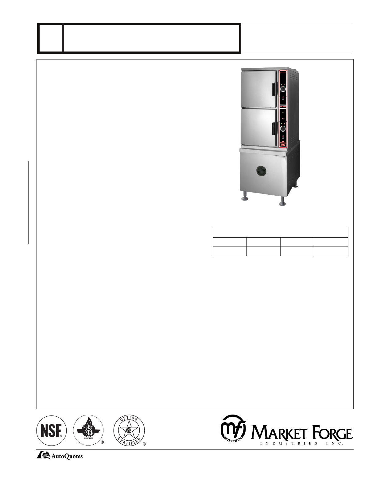
ST10-2G - (2) five pan convection steamer with separate gas steam
generators
DESCRIPTION
Shall be a Market Forge Convection Steamer with an Individual Gas
Steam Generator for each cavity.
The steamer shall be constructed of a satin finish stainless steel type
304. The cooking chamber is a one piece all welded type 316 stainless
steel with coved corners. The heavy duty door shall have an inner liner
of stainless steel with a full perimeter gasket seal, an outer liner of one
piece all welded stainless steel, and a positive lock and seal mechanism
with spring release. Each compartment shall be provided with removable stainless steel pan supports. A stainless steel drip trough shall be
integrally connected to drain to collect condensate when the doors are
opened.
The control housing shall be constructed of stainless steel with a full
access removable panel. Each compartment shall have individual
controls which include an illuminated three way power switch (On/Off/
De-lime), a pilot ready light, a pilot cooking light, an ignition light, a 60
minute electric timer which sounds an audible signal at the end of the
cooking cycle, solid state generator controls and electronic ignition for
each generator. Steam flow to the cooking chamber shall be cut off when
the door is opened and reactivated when the door is closed.
The steamer shall be mounted on a 24” cabinet base constructed of #4
Two Compartment Steamer
stainless steel with exterior hinged door and 6” (152mm) stainless steel
FOOD SERVICE EQUIPMENT
legs with adjustable flanged feet. The cabinet shall house the two generators, automatic blowdown and drain box.
STANDARD FEATURES:
De-lime mode power setting
Constant Steam
Automatic blow-down
Split water lines
Thermostatically controlled drain
Single drain connection
Electronic ignition
(4) 6” flanged feet
Redundant controls and generator for each compartment
All stainless steel constructed steam generator(s)
Safety relief valve
Left side access panel
De-liming ports on front of each generator
OPERATION SHALL BE BY:
190,000 BTU Gas fired, stainless steel steam generator(s) operating at 0
psi (0 kg/cm2) with controls equipped for operation on 120V, 1 pH, 60 Hz.
Natural gas.
L.P. gas.
CONVECTION STEAMER
JOB NAME: ___________________________
ITEM NO.: ____________________________
NO. REQUIRED: _______________________
CAPACITY
PAN DEPTH
1” 2-1/2” 4” 6”
20 10 6 4
SHIPPING WEIGHT
700 lbs (318 kg)
OPTIONS & ACCESSORIES
(at additional charge)
Pans & Covers
12” x 20” pan cover
12” x 20” x 1” solid pan
12” x 20” x 1” perforated pan
12” x 20” x 2-1/2” solid pan
12” x 20” x 2-1/2” perforated pan
12” x 20” x 4” solid pan
12” x 20” x 4” perforated pan
12” x 20” x 6” solid pan
12” x 20” x 6” perforated pan
Prison package, includes lockable stainless steel hinged
control cover, tamper proof screws
KleenSteam Filter System
Quick disconnect water lines ( 2) required
44 Lakeside Avenue, Burlington, VT 05401 USA • Tel: (802) 658-6600 • Fax: (802) 864-0183
www.mfii.com
Page 2
G
GAS TWIN GENERATOR
CONVECTION STEAMER
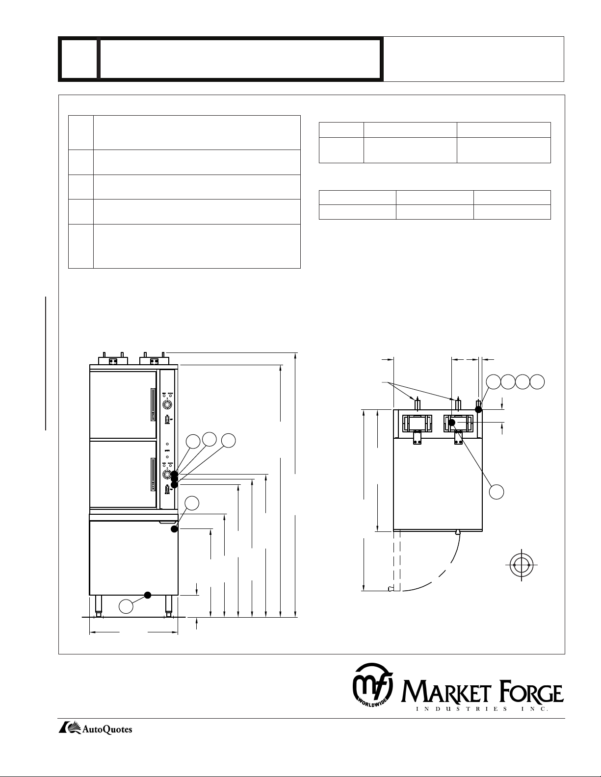
DETAILS & DIMENSIONS
SERVICE CONNECTIONS
EC Electrical Connection - 120V, 60 Hz, 1 pH with ground.
Unless otherwise specified. Furnished with a 6 foot cord
with 3 prong plug. Max 4.0 AMPS. 56 kW.
G Gas Connection - 3/4” (19mm) NPT Supply line
GAS SPECIFICATIONS
BTU/HR. NATURAL GAS (W.C.) PROPANE GAS (W.C.)
190,000 6” - 14”
(152-356mm)
12” - 14”
(305-356mm)
required.
C Condensing Cold Water - 3/8” (10mm) OD Tubing at
25-50 PSI (1.8-3.5 kg/cm2)
G1 Generator Water - 3/8” (10mm) OD Tubing at 25-50
PSI (1.8-3.5 kg/cm2)
D Drain - 2” (51mm) NPT pipe to open floor drain. DO
OVEN CLEARANCES
LEFT RIGHT BACK
0 0 6” (152mm)
* Use on non-combustible floors only.
NOT MAKE SOLID CONNECTION TO FLOOR DRAIN.
Max Length before open air gap opening: 24” (610mm)
NO BENDS OR ELBOWS.
IMPORTANT: Before connecting water to this unit, have water supply analyzed to make sure that hardness is no greater than 2.0 grains
per gallon and a pH level is within the range of 7.0–8.5. Water which fails to meet these standards should be treated by installing a filter
or conditioner. Equipment failure caused by inadequate water quality is not covered under warranty. Do not make solid connection to floor
drain. PVC and CPVC pipe are not acceptable materials for drains.
DIMENSIONS ARE IN INCHES [MM]
15.75 [400]
SAFETY RELIEF
VALVES
1 [25]
G1 C
EC
G
Two Compartment Steamer
FOOD SERVICE EQUIPMENT
D
24 [610]
C
6 [152]
EC
28 [711]
24 [610]
68.5 [1740]
33.13 [841]
71.88 [1825]
49.25 [1251]
38.75 [984]
36 [914]
37.5 [953]
G1
G
The manufacturer reserves the right to modify materials and specifications without notice.
3.5 [89]
D
REAR FLANGED
FOOT DETAIL
2 EQUALLY SPACED
Ø7/16” [11] HOLES
ON 2.5 [63] B.C.
PRINTED IN U. S. A.
SPEC SHEET: 14-0101 Rev B (3/15)
44 Lakeside Avenue, Burlington, VT 05401 USA • Tel: (802) 658-6600 • Fax: (802) 864-0183
www.mfii.com
 Loading...