

Page 1
ST10-2G
GAS TWO COMPARTMENT CONVECTION STEAMER
WITH TWIN GENERATORS
INSTALLATION - OPERATION - MAINTENANCE
44 Lakeside Avenue, Burlington, Vermont 05401 USA
Telephone: (802) 658-6600 Fax: (802) 864-0183
www.mi.com PN 14-0275 Rev A (8/14)
© 2014 - Market Forge Industries Inc.
Page 2

Your Service Agency’s Address:
Model
Serial number
Oven installed by
Installation checked by
Page 3

IMPORTANT
TABLE OF CONTENTS
WARNING: Improper installation, adjustment, alternation,
service or maintenance can
cause property damage, injury or death. Read the installation, operation and maintenance instructions thoroughly
before installing or servicing
this equipment.
INSTRUCTIONS TO BE FOLLOWED IN THE EVENT THE
USER SMELLS GAS MUST BE
POSTED IN A PROMINENT LOCATION. This information may
be obtained by contacting your
local gas supplier.
FOR YOUR SAFETY
Do not store or use gasoline or
other ammable vapors or liquids in the vicinity of this or any
other appliance.
INSTALLATION
Service Connections ..................................................... 2
Introduction .............................................................. 3
Installation............................................................... 4
Setting in Place ...................................................... 4
Mechanical Connections .............................................. 4
General ............................................................. 4
Exhaust Fans and Canopies .......................................... 4
Wall Exhaust Fan .................................................... 4
Clearances .......................................................... 4
To Install ............................................................ 4
Utility Connections ....................................................... 5
Performance Check ...................................................... 6
OPERATION
Cooking ................................................................. 7
Cleaning ................................................................ 8
Control Panel ............................................................ 9
Test Kitchen Bulletin ..................................................... 10
Cooking Guide .......................................................... 11
The information contained in this
manual is important for the proper installation, use, and maintenance of this oven. Adherence
to these procedures and instructions will result in satisfactory
baking results and long, trouble free service. Please read
this manual carefully and retain
it for future reference.
ERRORS: Descriptive, typographic or pictorial errors are
subject to correction. Specications are subject to change
without notice.
MAINTENANCE
Cleaning and Preventative Maintenance .................................. 13
Page 4
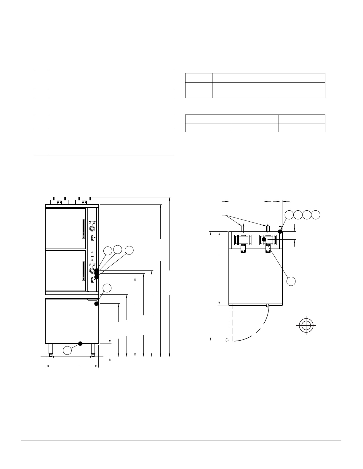
Service Connections
SERVICE CONNECTIONS
EC Electrical Connection - 120V, 60 Hz, 1 pH with ground.
Unless otherwise specified. Furnished with a 6 foot cord
with 3 prong plug. Max 4.0 AMPS. 56 kW.
G Gas Connection - 3/4” (19mm) IPS Supply line required.
C Condensing Cold Water - 3/8” (10mm) OD Tubing at
25-50 PSI (1.8-3.5 kg/cm2)
G1 Generator Water - 3/8” (10mm) OD Tubing at 25-50
PSI (1.8-3.5 kg/cm2)
D Drain - 2” (51mm) IPS pipe to open floor drain. DO NOT
MAKE SOLID CONNECTION TO FLOOR DRAIN. Max
GAS SPECIFICATIONS
BTU/HR. NATURAL GAS (W.C.) PROPANE GAS (W.C.)
190,000 6” - 14”
(152-356mm)
12” - 14”
(305-356mm)
OVEN CLEARANCES
LEFT RIGHT BACK
0 0 6” (152mm)
* Use on non-combustible floors only.
Length before open air gap opening: 24” (610mm) NO
BENDS OR ELBOWS.
IMPORTANT: Before connecting water to this unit, have water supply analyzed to make sure that hardness is no greater than 2.0 grains
per gallon and a pH level is within the range of 7.0–8.5. Water that fails to meet these standards should be treated by the installation of a
water conditioner. Equipment failure caused by inadequate water quality is not covered under warranty. Drain, 1-1/2” O.D. pipe coupled to
1 1/2” O.D. tempering tank drain. Do not make solid connection to floor drain. PVC and CPVC pipe are not acceptable materials for drains.
DIMENSIONS ARE IN INCHES [MM]
15.75 [400]
SAFETY RELIEF
VALVES
1 [25]
G1 C
3.5 [89]
EC
G
D
24 [610]
G1
G
C
6 [152]
EC
28 [711]
24 [610]
68.5 [1740]
33.13 [841]
D
71.88 [1825]
49.25 [1251]
38.75 [984]
36 [914]
37.5 [953]
REAR FLANGED
FOOT DETAIL
2 EQUALLY SPACED
Ø7/16” [11] HOLES
ON 2.5 [63] B.C.
Figure 1
InstallatIon
2
Page 5

Introduction
DESCRIPTION:
The ST10-2G series steamer is a pressureless steam
cooker consisting of two independently controlled compartments enclosed in a single cabinet. Each compart-
ment is equipped with a separate heavy duty door with
inner gasket plate isolated from the exterior surface. Door
latches operate by action for positive sealing of inner
door. Operation controls are displayed on a single frontmounted panel and include separate timers with indicator
lights for selection of constant steam or 60-minute-long
duration cooking. Two gas red, stainless steel generators operating at “0” psi (0 kg/cm2) and rated at 95,000
BTU are located in the bottom cabinet and may be operated separately.
BASIC FUNCTIONING:
The steamer may be operated with only one compartment in use; or both may be used simultaneously. Each
compartment is equipped with identical controls, allowing
selection of constant steam or 60-minute timer operation.
The cooker becomes operational when it is set to constant steam, or the timer is set at the desired cooking time
and the compartment door is closed.
When steam owing inside the compartment has raised
the interior temperature to 195°F, the contacts of a thermostatic switch close, completing the circuit to the timer
motor and starting the cooking time period. At the end of
the set interval, timer contacts switch to shut off the cooking operation and sound a signal buzzer. The buzzer is
silenced by returning the timer dial to the OFF position. In
the constant steam mode, operation will be continuous.
Steam emitted from the compartment along with liquid
cooking drainage is directed through a drain screen inside
the compartment into the cooker drain line to the generator drain box that is automatically actuated by a thermostatic cooling valve to condense the steam to water prior
to discharge into the oor drain.
PAN CAPACITY
PAN DEPTH
1” 2-1/2” 4” 6”
20 10 6 4
STANDARD FEATURES
• De-lime mode power setting
• Constant Steam
• Automatic blow-down
• Split water lines
• Thermostatically controlled drain
• Single drain connection
• Electronic ignition
• 2 rear anged feet
• Redundant controls and generator for each compart-
ment
• All stainless steel constructed steam generator(s)
• Safety relief valve
• Left side access panel
• De-liming ports on front of each generator
GAS OPERATION
190,000 BTU
• Natural gas.
• L.P. gas.
Gas red, stainless steel steam generator(s) operating at
0 psi (0 kg/cm2) with controls equipped for operation on
120 V, 1 pH, 60 Hz.
3
InstallatIon
Page 6

Installation
SETTING IN PLACE
The location of installation must be under an exhaust
hood, which will remove small amounts of water vapor
emitted when the cooker doors are opened, and exhaust
fumes. Level the unit in nal location by turning the adjustable feet. Using the cabinet top as a reference, obtain
level adjustment left-to-right and front-to-back.
MECHANICAL CONNECTIONS
Since the Pressureless Cooker is interconnected at the
factory to the steam boiler, no eld connections to the
cooker are required. All electrical and plumbing connec-
tions are located on the rear middle panel of the cabinet.
GENERAL
Gas installation to conform to local codes, or in absence
of local codes, with the National Fuel Gas Code - ANSI
Z223.1/NFPA 54. In Canada installation to be in accordance with the Natural Gas and Propane Installation
Code, CSA B149.1. and or local codes.
1. The appliance and its individual shut off valve must
be disconnected from the gas supply piping system
during any pressure testing of that system at pressures in excess of 1/2 PSI (0.03 kg/cm2).
2. The appliance must be isolated from the gas supply
piping system by closing its individual manual shut
off valve during any pressure testing of the gas sup-
ply piping system at test pressures equal to or less
than 1/2 PSI (0.03 kg/cm2). Electrical grounding must
be provided in accordance with local codes, or in the
absence of local codes, with the National Electrical
Code ANSI/NFPA 70. In Canada, installation must
be in accordance with the Canadian Electrical Code
CSA C22.2.
WARNING
Electrical grounding instructions - Units come
equipped with a three-prong (grounding) plug
for your protection against shock hazard and
should be plugged directly into a properly
grounded three-prong receptacle. Do not cut
or remove the grounding prong from this plug.
(120 VOLT UNITS ONLY).
EXHAUST FANS AND CANOPIES
Canopies are set over ranges, ovens, kettles, etc., for
ventilation purposes. It is recommended that a canopy
extend 6” past the appliance and be located 6’ 6” from the
oor. Filters should be installed at an angle of 45 degrees
or more with the horizontal. This position prevents dripping of grease and facilitates collecting the run-off grease
in a drip pan, usually installed with the lter. A strong exhaust fan tends to create a vacuum in the room and may
interfere with burner performance or may extinguish pilot
ames. Makeup air openings approximately equal to the
fan area will relieve such vacuum. In case of unsatisfactory performance on any appliance, check with the exhaust
fan in the “OFF” position.
WALL EXHAUST FAN
The exhaust fan should be installed at least two feet
above the vent opening at the top of the unit.
CLEARANCES
Adequate clearance must be provided in aisle and at the
side and back. Adequate clearances for air openings into
the combustion chamber must be provided, as well as for
serviceability for use on noncombustible oors. Minimum
clearance from combustible and noncombustible construction, 0” on left side, 0” on right side and 6” from back.
WARNING
These procedures must be followed by quali-
ed personnel or warranty will be voided. An
open gap oor drain is required immediately
below the appliance drain.
TO INSTALL
1. Uncrate carefully. Report any freight damage to the
freight company immediately.
2. Set the unit in place. Be certain to maintain the minimum clearances from combustibles and non-combustibles.
3. For an appliance supplied with legs, level the appli-
ance using a spirit level. Should anged adjustable
feet be provided, anchor to oor using proper anchor-
ing devices.
InstallatIon
4. Seal bolts and anged feet with Silastic or other
equivalent compound.
5. Be certain to leave adequate clearances for cleaning,
maintenance and service.
4
Page 7

Utility Connections
GAS CONNECTION
1. The Serial and Rating Plate on the unit indicates the
type of gas your unit is equipped to burn. DO NOT
connect to any other gas type.
2. A 3/4” NPT line is provided at rear for the connec-
tion. Each compartment is equipped with an internal
pressure regulator which is set at 3.5” W.C. manifold
pressure for natural gas and 10” W.C. for propane
gas. Use c” pipe tap on the burner manifold for checking pressure.
An adequate gas supply is imperative. Undersized or low
pressure lines will restrict the volume of gas required for
satisfactory performance. A steady supply pressure, between 6” W.C. and 14” W.C. for natural gas and 11” W.C.
and 14” W.C. for propane gas is recommended. With all
units operating simultaneously, the manifold pressure on
all units should not show any appreciable drop. Fluctuations of more that 25% on natural gas and 10% on propane gas will create problems, affecting burner operation.
Contact your gas company for correct supply line sizes.
Purge the supply line to clean out any dust, dirt or other
foreign matter before connecting the line to the unit. Use
pipe joint compound which is suitable for use with Liquid
Propane on all threaded connections.
Test pipe connections thoroughly for gas leaks.
• Use soapy water only for testing on all gases.
• Never use an open ame to check for gas leaks.
• All the connections must be checked for leaks after
the unit has been put in operation.
ELECTRICAL CONNECTION
120 VAC-60 Hz - Single Phase
Units with this electrical rating are factory supplied with a
three-wire cord and three-prong plug which ts any standard 120V, three-prong grounded receptacle. A separate
15 amp supply is needed for each unit.
PLUMBING CONNECTION
WARNING
Plumbing connections must comply with applicable Sanitary, Safety and Plumbing Codes.
Two water lines are provided. Connect water supply lines
to the 3/8” copper tubes at the rear of the steamer.
One line is for supply of water to the generator and one
for cold condensate water to condense live steam entering the drain line.
DRAIN CONNECTIONS
Appliance drain is 2 inch pipe size. Provide open air gap
type drain.
WARNING
An open gap oor drain is required immediately below the appliance drain. PVC OR CPVC
are not acceptable materials for drains.
COLD WATER CONDENSER
The steamer is equipped with a cold water condenser, in
the rear of the cooking chamber, which helps to condense
the steam prior to discharge into the drain. The steamer
freely vents itself by the negative pressure created by the
condensate water drainage. This negative pressure prevents steam leakage around the door gasket and helps
draw the steam through the cooking compartment. Steam
leakage at the door may indicate a plugged or improperly
installed drain.
Temperature of condensate water owing through the
drain is controlled by the thermostatic cooling valve (TCV)
located inside the controls compartment on the right side
of the unit. The valve has been factory set to keep con-
densate water owing into the drain at or below 140°F.
Depending on local plumbing code requirements, this
setting may be changed to obtain a different maximum
drainage temperature. Refer to next section Performance
Check for instructions to set the (TCV).
WATER CONDITIONING
It is important that the water supplied to the generator be
softened to no more than 2.0 grains of hardness and have
a pH of 7.0 to 8.5. This degree of hardness can be easily
obtained with the use of a properly maintained water softener. The use of a water meter will determine the water
consumption and when the water softener needs regeneration or recharging. Failure to comply with these water
condition standards may void the warranty.
Untreated water contains scale producing minerals which
can precipitate onto the surfaces in the steam generator.
Due to the temperatures in the steam generator, the minerals can bake onto the surfaces and components. This
can result in early component failure and reduced product
life. Water level probes become coated with scale. Scale
may bridge across the probe insulator from the metal extension which senses the water level in the steam generator shell.
Once this scale becomes wet, the water level control is
unable to maintain the proper water level in the steam
generator.
STRAINERS and FILTERS will NOT remove minerals
from the water.
5
InstallatIon
Page 8

Performance Check
WARNING
The steamer and its parts are hot. Use care
when operating, cleaning or servicing the
steamer. The cooking compartment contains
live steam. Stay clear while opening door.
Once the steamer is installed and all mechanical connections have been made, thoroughly test the steamer before
operation.
1. Check that proper water, drain and electrical and gas
connections have been made.
2. Turn main power switch ON.
3. Check that “Ignition” light comes on and that burners
ignite.
4. After approximately 15 minutes, the “READY” light
should come on, indicating that the water temperature has reached 205oF (97oC). At this time, set timer
to the “5 minute” position. With door open, observe
that no steam is entering the compartment and that
the “COOKING” light is OFF.
5. Close compartment door. The COOKING light should
now illuminate and steam should be heard entering
the compartment shortly after.
7. Open compartment door and observe that steam
supply to compartment is cut off.
8. “READY” light should again come on as “COOKING”
light turns “OFF”.
9. Close compartment door and observe cooker operation for several minutes. Operation is correct if
timer dials begin to rotate after a short delay period
required for preheating. After the delay period plus
the “5-Minute” initial setting, the timer dials will return
to the “0-Minute” position, at which a buzzer sounds.
The buzzer is silenced by turning the dial to the “OFF”
position.
10. With all compartments of the steamer operating in the
cooking cycle, check the temperature of the condensate coming out the drain. If the drain temperature
exceeds local plumbing code requirements, adjust
the Thermostatic Cooling Valve (TCV) out for a lower
drain temperature and in for a higher drain temperature. A TCV setting of approximately 2.75 yields a
drain temperature of 140°F. A setting of approximately 2.5 or 3 yields temperatures of 125°F and 155°F,
respectively.
6. After ve minutes of operation check that water from
the cold water condenser is owing through the drain
line.
InstallatIon
6
Page 9

Cooking
LIGHTING
1. Ensure power, gas and water supply is on.
2. Turn power switch “ON”.
3. Steam generator tanks will begin lling with water.
4. Once proper water level has been reached, the ignition light will come on and should remain on until the
ready light comes on.
5. Cooker is now ready for use.
Your steamer has been factory set, when “ON” to maintain water temperature during the READY phase at approximately 205º Fahrenheit (97º Celsius) just below water boiling point.
WARNING
In the event of main burner ignition failure, a
5 minute purge period must be observed prior
to re-establishing ignition source.
WARNING
In the event a gas odor is detected, shut down
equipment at the main shut off valve and contact the local gas company or gas supplier for
service.
PREHEATING
Before each initial operation of the cooker, and at any other time when the cooking compartment is cold, a 1-minute
preheating period is required. To preheat the cooker, put
steam source into operation and proceed as follows:
1. Close cooking compartment door.
2. Set 60-Minute Timer Dial (1) to “1-minute” setting.
NOTE: Total elapsed preheating time equals the tim-
er setting plus a short delay period needed
to activate a thermostatic switch included in
the controls.
3. Turn off buzzer, which sounds to indicate cooking is
complete, by setting the Timer Dial (1) to OFF position.
COOKING
Before loading the cooker, be sure compartment is hot.
See preheating instructions.
1. Slide pans of food into cooking compartment pan
supports.
2. Close cooking compartment door.
3. Set timer cooking time:
a. CONSTANT STEAM - for continuous cooking.
b. 60-MINUTE TIMER - for timed cooking.
4. Set appropriate timer to the required cooking time
(see Cooking Guidelines).
5. Turn off buzzer, which sounds to indicate cooking is
complete, by setting timer dial (1) to the OFF position.
6. Open door slightly at rst letting most of the steam
out of the compartment and then fully open the door.
7. Unload by sliding pans of food from pan supports.
SHUT-DOWN PROCEDURE
No shut-down procedure is required for the cooker except
to check that both timer dials (1) are in the OFF position and that both compartment doors are open. When
all cooking has been completed for the day, the steam
source must be shut off.
COMPLETE SHUTDOWN
1. Set timer to “OFF” and turn power switch “OFF”.
Steam generator will drain automatically.
2. Turn water supply “OFF”.
3. Close manual gas shutoff valve.
4. Disconnect power supply.
CAUTION
When the unit is not in use, leave the cooking
compartment door slightly ajar to prolong the
life of the door gasket.
7
operation
Page 10

Cleaning
CLEANING
After each period of daily operation (more frequently as
required to maintain cleanliness), the cooker should be
thoroughly cleaned by completing the following steps:
1. Remove left and right side pan supports and drain
screens by lifting up and off mounting studs. Remove
drain screen by pulling straight out. Wash with a mild
detergent. Rinse and set aside for reassembly.
2. Wash cooking compartment interior using a mild detergent and water. Rinse and dry thoroughly.
3. Replace pan supports and drain screens in compartment and leave door open.
DRAINAGE
Cooking Compartment Drainage:
The bottom of the cooking compartment is angled slightly
toward the rear of the unit. This assures that any condensate build-up or spills will be directed toward the drain,
which is located at the rear bottom center of the cooking
compartment. Any liquid exiting the cooking compartment
runs down the cooking compartment drain tube and into
the drain line.
Drip/Spill Trough Drainage:
The Pressureless Steam Cookers have a drip/spill trough
below the cooking compartment door.
It will catch any condensate gathering on the front of the
unit when the door is opened.
WARNING
The steamer and its parts are hot. Use care
when operating, cleaning or servicing the
steamer. The cooking compartment contains
live steam. Stay clear when opening door.
CAUTION
An obstructed drain can cause personal injury
or property damage.
operation
8
Page 11

Control Panel
CONTROL FUNCTION
1. Ignition Light - When lit, indicates burners have been
ignited and are heating the steam generator tank.
2. Ready Pilot Light - When lit, indicates steam generator has reached 205oF (97oC) and is ready for the
cooking cycle.
3. Cooking Pilot Light - When lit, indicates that a cooking cycle is in progress.
4. Timer /Constant Steam - Set the cooking time (0-60
minutes) – steam cooking will begin when the door
is closed. The cooking cycle will be interrupted if the
door is opened during the cooking cycle; resume
cooking by closing the door. Constant Steam - For
continuous cooking.
5. Main Power Switch -
DELIME - Closes the drain valve while CLR liquid is
being poured into the steam generator during the Delime procedure. Amber light will ignite on the main
power switch.
ON - The steam generator will automatically ll and
begin heating to the pre-set temperature. Red light
will ignite on the main power switch.
OFF - The steam generator will drain. No lights.
6. Buzzer - Signals end of cooking period (not shown).
Figure 2
9
operation
Page 12

Test Kitchen Bulletin
NOTE: Each cooking compartment has its own steam
generator and controls and can be operated independently.
1. Frozen vegetables should always be cooked in perforated 12” x 20” x 2-1/2 “pans 7 1/2 lb. (34 kg) maximum per pan.
2. Frozen entrees should be underlined with a perforat-
ed pan for best results. If they are defrosted rst, the
heating time will be decreased.
3. Fresh foods may also be cooked in this unit. Vegetables and other foods where the stock is not to be
retained should be cooked in perforated 12” x 20” x
2-1/2” pans for the most nutritious results.
4. There is a thermostatic time delay built into this unit
which adapts the unit to the proper cooking time. This
means that the total time will usually be longer than
the time setting.
5. There is a safety microswitch on the door which shuts
off the steam each time the door is opened if the unit
is in the cooking cycle.
6. Both compartments may be lled and timers set simultaneously.
15. Food such as potatoes, poultry, seafood, and some
meats may be blanched in the steam cooker, thus reducing the total cooking time and grease absorption.
16. Fuel is used only when the steam cooking unit is in
operation.
17. The steam cooker will loosen foods burned on pans
making washing easier.
18. Solid pans are recommended when liquid is to be re-
tained and perforated pans when the liquid is not to
be retained.
19. Eggs may be cooked out of the shell if they are to be
chopped which eliminates peeling after steaming.
20. The steam cooker can be opened during the cooking
period to add or remove items.
21. Steam cooking information, including recommended
pan size and type, weight per pan, cooking times and
pan yields are given on the following pages of this
bulletin.
7. Total cooking time will vary depending on the load,
even though the timer setting is the same.
8. All foods, except cakes and pastry, can be cooked in
a steam cooking unit.
9. Steam cooked meals have greater nutritional value
since they retain most of their vitamins and minerals.
10. Because foods are cooked faster by the higher temperatures of steam cooking, they can be prepared
closer to serving time, insuring maximum freshness.
11. Steam cooked foods have a higher percent yield
more portions per dollar spent.
12. Food may be served from the same pan in which it
is steam cooked, thus reducing food breakage since
there is no extra handling or transferring of food from
cooking pans to serving pans. It also reduces pot
washing tasks.
13. Some important advantages of steam cooking are labor saving, reduced operating costs, space saving,
and the lifting of heavy stock pots is eliminated.
14. Rice and spaghetti products, if thoroughly wet at the
start of the cooking process are very easily prepared.
operation
10
Page 13

Cooking Guide
STEAM COOKING:
The Pressureless Cooker is a two compartment unit. The ST10-2G holds ten 12” x 20” x 2-1/2” or six 12” x 20” x 4” pans.
This enables the cook to prepare foods close to the time of service. The cooking times given are timer settings and should
be set on a preheated compartment. There is a thermostatic time delay in each compartment that adjusts the total time
depending on the temperature and amount of the food. Therefore, the total time will be greater than the timer setting. At the
end of the timer cooking cycle the buzzer will sound, steam will stop owing and the food can be removed.
COOKING GUIDELINES:
The following guidelines given are suggested quantities, time settings and estimated numbers of orders per pan.
FROZEN
ITEM
FROZEN VEGETABLES
Asparagus, Spears 7.5 lbs (3.4 kg) 2.5” (65mm) 1-3 12-15 30 - 3 oz (85g)
Beans, Green Regular 6 lbs (2.7kg) 2.5” (65mm) 1-3 10-15 25 - 3 oz (85g)
Beans, Green French
Cut
Beans, Lima 7.5 lbs (3.4 kg) 2.5” (65mm) 1-3 12-15 30 - 3 oz (85g)
Broccoli 6 lbs (2.7kg) 2.5” (65mm) 1-3 4-6 25
Brussel Sprouts 7.5 lbs (3.4 kg) 2.5” (65mm) 1-3 10-15 30 - 3 oz (85g)
Carrots 6 lbs (2.7kg) 2.5” (65mm) 1-3 10-15 25 - 3 oz (85g)
Cauliower 6 lbs (2.7kg) 2.5” (65mm) 1-3 7-12 25 - 3 oz (85g)
Corn, Cut 7.5 lbs (3.4 kg) 2.5” (65mm) 1-3 8-12 30 - 3 oz (85g)
Mixed, Vegetables 7.5 lbs (3.4 kg) 2.5” (65mm) 1-3 8-12 30 - 3 oz (85g)
Peas, Loose 7.5 lbs (3.4 kg) 2.5” (65mm) 1-3 3-5 30 - 3 oz (85g)
Spinach 9 lbs (4 kg) 2.5” (65mm) 1-3
Squash 12 lbs (5.5 kg) 2.5” (65mm) 1-3
FROZEN PREPARED ENTREES
Lobster Tails,
6-8oz. (170-255g)
Shrimp, C.D.P. 16-20 lbs (7-9 kg) 2.5” (65mm) 1-3 8-11 75
Shrimp, Green 16-20 lbs (7-9 kg) 2.5” (65mm) 1-3 11-15 50
Bulk Pack, Frozen
Bulk Pack, Defrosted 3.5-4 2.5” (65mm) 1-3 25-35 10
MISCELLANEOUS
Eggs, in Shell 3 dozen 2.5” (65mm) 1-3 9-11 36 - 1 Egg each
Eggs, out of Shell 4 dozen 2.5” (65mm) 1-3 6-8 48 - 1 Egg each
Rice 4 lbs (1.8 kg) 2.5” (65mm) 1-3 18-22 60-65 - 3 oz (85g)
Spaghetti 3 lbs (1.4 kg) 2.5” (65mm) 1-3 18-22 40-45 - 4 oz (115g)
WEIGHT PER
PAN
6 lbs (2.7kg) 2.5” (65mm) 1-3 5-7 25 - 3 oz (85g)
7-8 lbs (3.2-3.6
kg)
3.5-4 lbs
(1.6-1.8 kg)
RECOMMENDED
12” x 20” (1/1)
PERF. PAN
2.5” (65mm) 1-3 15-25 15
2.5” (65mm) 1-3 35-45 10
NO. OF
PANS
TIMER
SETTINGS
IN MINUTES
Must be
Defrosted
Must be
Defrosted
APPROX. NO. COOKED
SERVINGS PER PAN
30 - 4 oz (115g)
50 - 3 oz (85g)
11
operation
Page 14

Cooking Guide
ITEM
VEGETABLES
FROZEN
WEIGHT PER
PAN
RECOMMENDED
12” x 20” (1/1)
PERF. PAN
NO. OF
PANS
TIMER
SETTINGS
IN MINUTES
APPROX. NO.
COOKED
SERVINGS PER PAN
Beans, Snap Green or Wax 6 lbs (2.7 kg) 2.5” (65mm) 1-3 18-22 25-30 - 3 oz (85 g)
Beets, 2” (50mm)
Diameter
Broccoli, 1/2-3/4”
(12-20mm) Stalks
7.5 lbs (3.4 kg) 2.5” (65mm) 1-3 40-50 30-35 - 3 oz (85 g)
6 lbs (2.7 kg) 2.5” (65mm) 1-3 14-18 25-30 - 3 oz (85 g)
Carrots, Sliced 9 lbs (4 kg) 2.5” (65mm) 1-3 18-21 35-40 - 3 oz (85 g)
Cauliower, 1.5-2”
(38-50mm) Trimmed
6 lbs (2.7 kg) 2.5” (65mm) 1-3 12-16 30-35 - 3 oz (85 g)
Corn on the Cob, Husked 1 dozen 2.5” (65mm) 1-3 10-15 12
Cabbage, 1/4-1/6 of Head,
Cored
Onions, 2” (50mm)
Diameter
5 lbs (2.25 kg) 2.5” (65mm) 1-3 14-18 15-20 - 4 oz (115 g)
6 lbs (2.7 kg) 2.5” (65mm) 1-3 20-25 25-30 - 4 oz (115 g)
Peas, Shelled 5 lbs (2.25 kg) 2.5” (65mm) 1-3 5-6 25-30 - 3 oz (85 g)
Potatoes, French Fry Cut 10 lbs (4.5 kg) 2.5” (65mm) 1-3 18-21 50 - 3 oz (85 g)
Potatoes, 3” (75mm)
Regular Cut
10 lbs (4.5 kg) 2.5” (65mm) 1-3 35-40 50 - 3 oz (85 g)
Spinach, Cleaned & Cut 3 lbs (1.4 kg) 2.5” (65mm) 1-3 3-5 10-12 - 3.75 oz (105 g)
Summer Squash,
1” (25mm) Sliced
7 lbs (3.2 kg) 2.5” (65mm) 1-3
Winter Squash, Peeled 9 lbs (4 kg) 2.5” (65mm) 1-3
Turnip, Diced 5 lbs (2.25 kg) 2.5” (65mm) 1-3
MEAT - POULTRY - FISH
Chicken, Cut up
Chicken, 4 lbs. Whole
Fowl, 5 lbs.+ Whole
Fish, Fillets
Frankforts
Hamburgers, 3 oz. (85g)
Meatballs, 1 oz. (30g) size*
Meatloaf *
Pork Chops, Loin Bone,
4 oz. (115g)
Sausage, 1.5 oz. (45g)
Turkey, on Carcass
Turkey, off Carcass
8 lbs (3.6 kg) 2.5” (65mm) 1-3
3 each 2.5” (65mm) 1-3
2 each 2.5” (65mm) 1-3
3 lbs (1.4 kg) 2.5” (65mm) 1-3
5 lbs (2.3 kg) 2.5” (65mm) 1-3
5 lbs (2.3 kg) 2.5” (65mm) 1-3
6 lbs (2.7 kg) 2.5” (65mm) 1-3
15 lbs (6.8 kg) 2.5” (65mm) 1-3
6 lbs (2.7 kg) 2.5” (65mm) 1-3
6 lbs (2.7 kg) 2.5” (65mm) 1-3
20-22 lbs
(9-10 kg)
10-12 lbs
(4.5-5 kg)
2.5” (65mm) 1-3
2.5” (65mm) 1-3
7-10
10-15
28-32
20-30
45-50
50-60
10-15
3-5
18-22
20-25
40-50
25-30
18-21
2-2.5 Hours
1-1.25 Hours
30-35 - 3 oz (85 g)
25-30 - 3 oz (85 g)
20-25 - 4 oz (115 g)
15-20 - 2 oz (55 g)
25-30 - 2 oz (55 g)
20-25 - 2 oz (55 g)
12-15 - 2 oz (55 g)
35-40 - 2 oz (55 g)
20-25 - 2 oz (55 g)
20-25 - 2 oz (55 g)
50-60 - 2 oz (55 g)
24 - 2 oz (55 g)
18-20 - 2 oz (55 g)
50-60 - 2 oz (55 g)
55-65 - 2 oz (55 g)
* Raw weight for Meatballs and Meatloaf includes hamburg and extenders and yields 2 oz. (55g) protein plus extenders or
3 oz. (85g) total portion.
operation
12
Page 15

Cleaning and Preventative Maintenance
PREVENTIVE MAINTENANCE
A good preventive maintenance program begins with the
daily cleaning procedure. Additional preventive maintenance operations are presented in this section. In establishments that employ full-time maintenance personnel,
the tasks described can be assigned to them. For other
installations, tasks requiring mechanical or electrical experience should be performed by an authorized service
agency.
The following paragraphs set for minimum preventive
maintenance procedures that must be completed periodically to assure continued trouble-free operation of the
cooker.
CAUTION
Under no circumstances should hardware
(or parts) be replaced with a different length,
size, or type other than as specied in the
parts list. The hardware used in the cooker
has been selected or designed specically for
its application, and the use of other hardware
may damage the equipment and will void any
warranty.
MONTHLY - REMOVAL OF SCALE DEPOSITS
It is recommended that your steamer be delimed once a
month or more often if necessary.
Should your steamer develop a heavy build-up of lime
scale deposits, use the CLR
TREATMENT KIT available from your authorized servicer.
Before beginning deliming procedures, ensure that water
is not overowing into the cooking compartment.
DELIMING PROCEDURE
WARNING
Read and follow instructions on the CLR
bottle. Use plastic or rubber gloves to avoid
skin contact. If CLR comes in contact with
skin, rinse with clean water.
1. Completely drain steam generator by setting on/off
switch to “OFF”. Set cooking timer to 0.
2. Set on/off switch to DELIME.
3. Unscrew deliming port located in front of generator.
Screw in the supplied deliming funnel.
NOTICE
As a safety precaution, disconnect the power
supply during cleaning or servicing.
WARNING
The steamer and its parts are hot. Use care
when operating, cleaning or servicing the
steamer. The cooking compartment contains
live steam. Stay clear when opening door.
WEEKLY CLEANING
Weekly, or more often if necessary...
1. Clean exterior with a damp cloth and polish with a soft
dry cloth.
2. Use a non-abrasive cleaner to remove discolorations.
3. Clean around burner air mixer and orice if lint has
accumulated.
4. Make sure funnel is in upright position. Pour 200
ounces of solution into generator slowly to avoid spillage. Remove funnel and screw in delime port cap
securely. Turn on/off switch to “ON”. Use a towel to
protect the burners below from any spillage.
5. Operate steamer in READY cycle for ½ hour, then
turn on/off switch “OFF” and allow generator to drain.
6. Flush cycle. Turn on/off switch to “ON”. When ready
light comes on, switch to “OFF” to ush generator.
Repeat this step three times to completely ush gen-
erator.
7. Clean exterior and interior. Use a mild solution of
soap and water. Rinse with clean water. Dry with a
soft cloth. LEAVE COMPARTMENT DOOR OPEN
WHEN NOT IN USE.
The steamer is now ready for use. Turn off for overnight
shutdown.
13
maintenance
 Loading...