

Page 1

ST10-2G
GAS TWO COMPARTMENT CONVECTION STEAMER
WITH TWIN GENERATORS
PARTS AND SERVICE MANUAL
EFFECTIVE AUGUST 12, 2014
The Company reserves the right to make substitution in the event that items specied are not available.
ERRORS: Descriptive and/or typographic errors are subject to correction.
44 Lakeside Avenue, Burlington, Vermont 05401 USA Telephone: (802) 658-6600 Fax: (802) 860-3732
Superseding All Previous Parts Lists.
MARKET FORGE INDUSTRIES
www.mi.com
P/N 14-0289 Rev A (8/14)
Page 2

TABLE OF CONTENTS
WIRING DIAGRAMS ...................................................................3
TROUBLESHOOTING ..................................................................7
ADJUSTMENTS ......................................................................11
ILLUSTRATED PART LIST
COMPLETE EXPLODED VIEW ....................................................... 12
DOOR ASSEMBLY ................................................................... 15
BURNER PARTS ..................................................................... 16
GAS ASSEMBLY ..................................................................... 17
CONTROL BOARD ................................................................... 18
AUGUST 12, 2014 2 ST10-2G STEAMER
Page 3
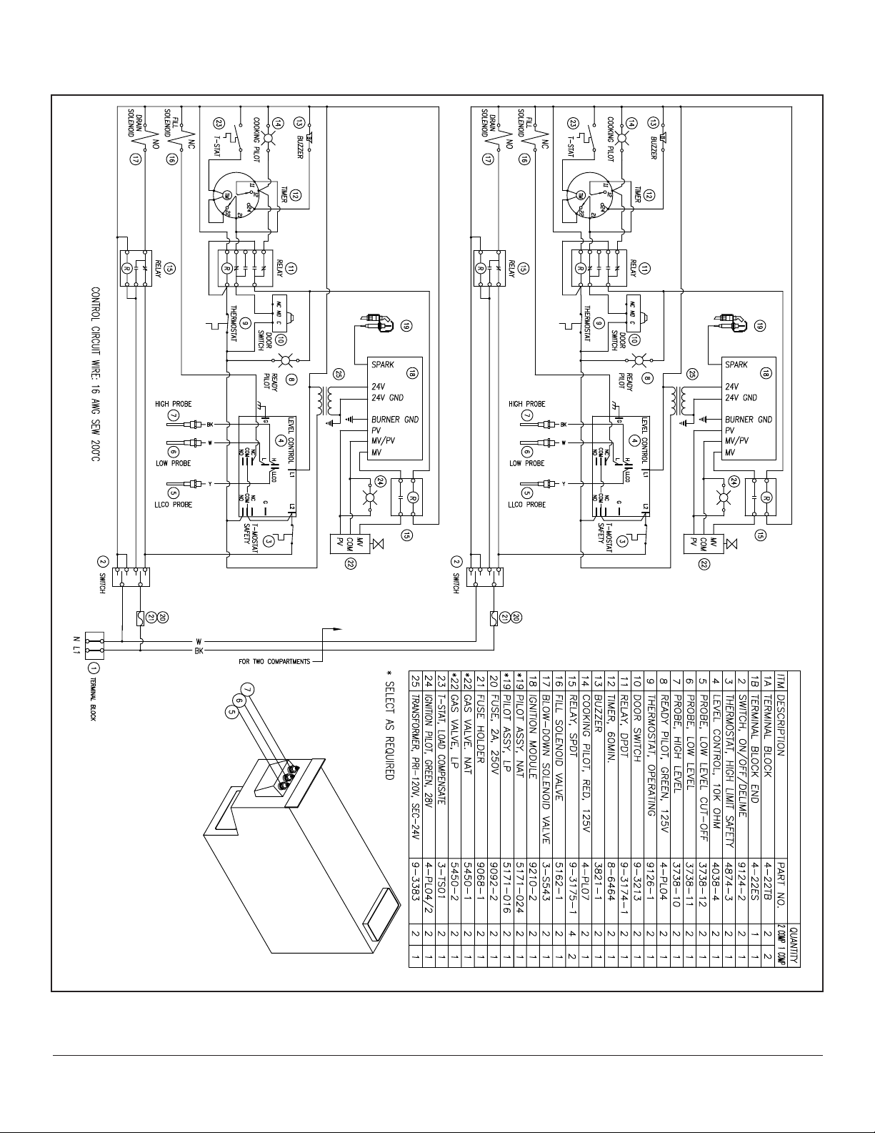
WIRING DIAGRAMS
MODEL: ST10-2G
(120V)
AUGUST 12, 2014 3 ST10-2G STEAMER
Page 4
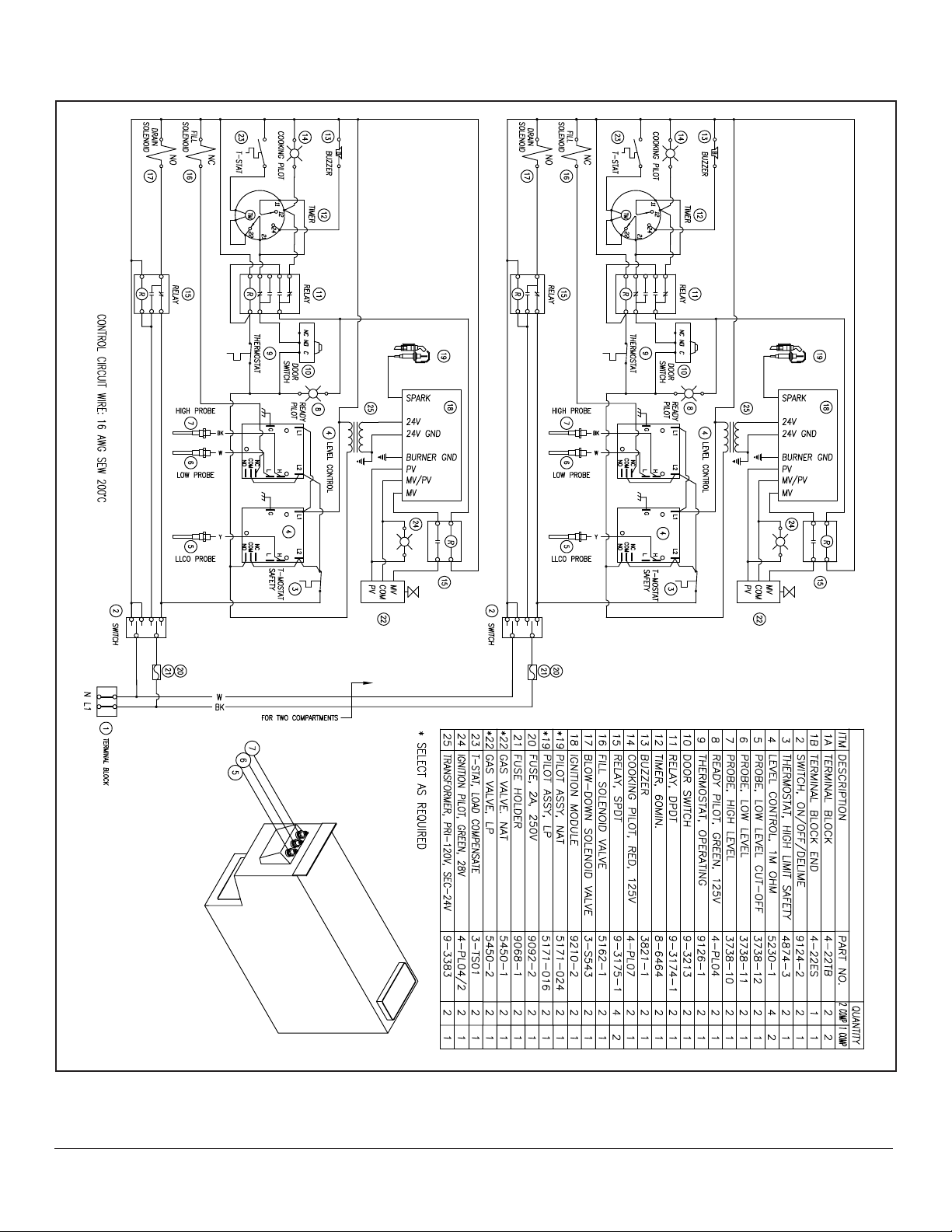
WIRING DIAGRAMS
MODEL: ST10-2G
(120V, R.O.)
AUGUST 12, 2014 4 ST10-2G STEAMER
Page 5
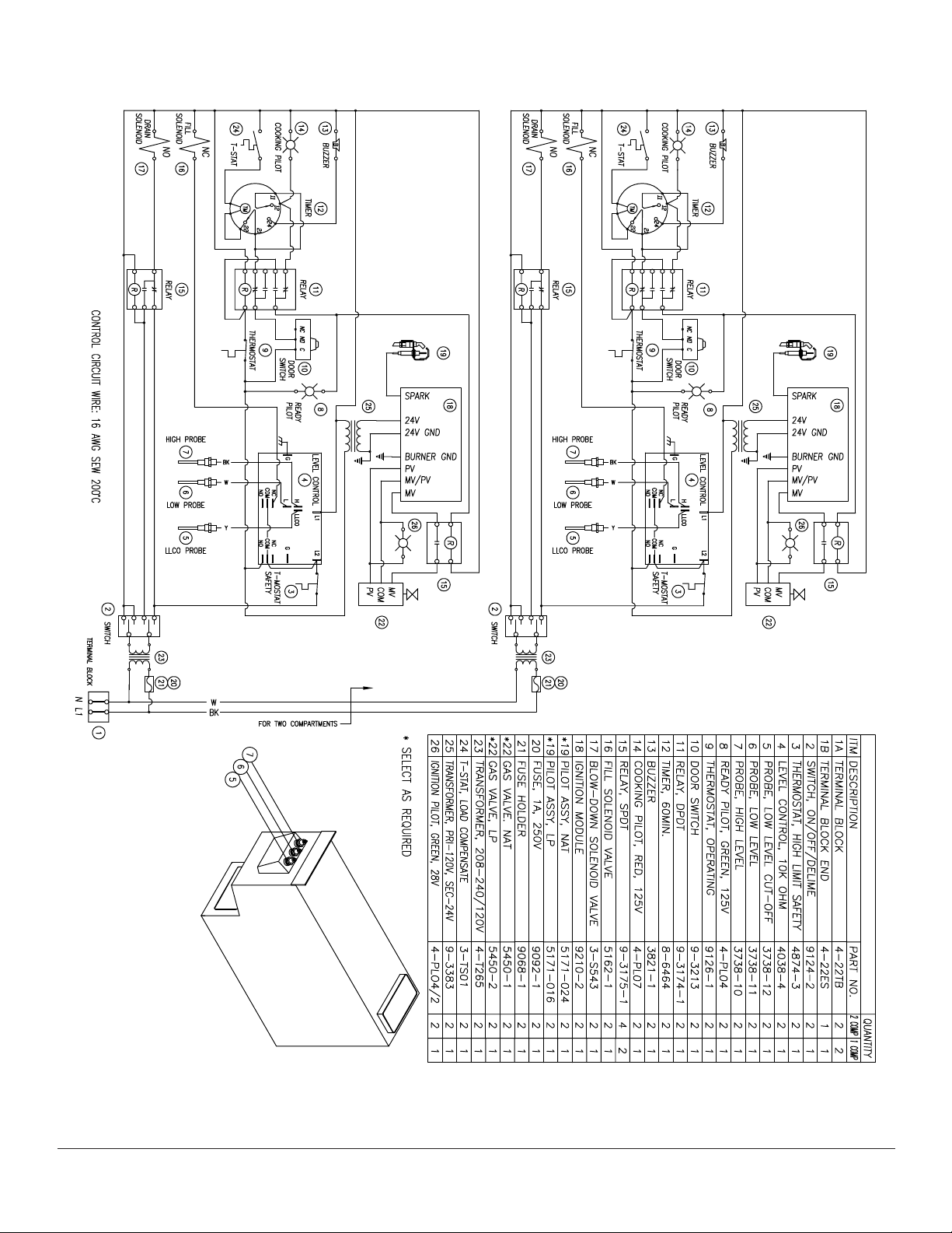
WIRING DIAGRAMS
MODEL: ST10-2G
(220V)
AUGUST 12, 2014 5 ST10-2G STEAMER
Page 6
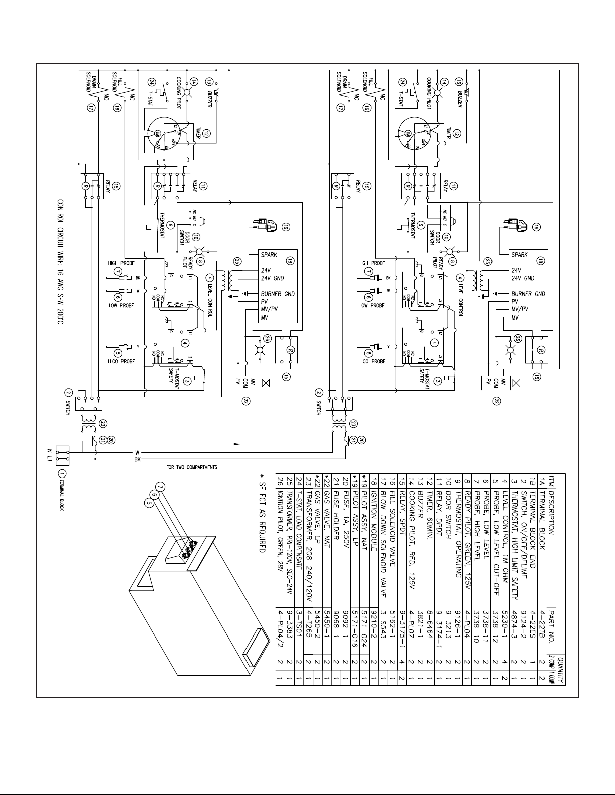
WIRING DIAGRAMS
MODEL: ST10-2G
(220V, R.O.)
AUGUST 12, 2014 6 ST10-2G STEAMER
Page 7

TROUBLESHOOTING
GENERAL
The information in this section is intended to assist both
the operator and service personnel in locating the general source of problems that may occur with the cooker.
Before following any of the procedures given in this section, the operator should be thoroughly familiar with the
operating instructions and the function of all controls that
are described. If the problem cannot be readily corrected,
the operator should contact the nearest service agency
for assistance.
The electrical troubleshooting procedures that follow require access to components and terminals of the electrical control panel. Electrical controls are reached by removing screws that fasten the control panel to the frame.
The panel may be pulled forward for testing while interconnected to the cooker circuits or disconnected at the
pin connection for complete removal and repair.
INCOMING POWER
Before troubleshooting any of the electrical parts or assemblies, verify that power is being supplied to the cooker. Incoming power is connected to the terminal block in
the upper controls section, accessible by the right side
panel. With power connected to the cooker, an AC voltmeter is used to measure 120 volts across L1 and L2. If
120 volts is present, and the cooker will not operate, the
fault lies within the electrical circuits of the cooker.
WARNING
Before removing control panel or checking
connections and wiring, be sure that the circuit breaker for incoming power is OFF. When
power is supplied, all exposed terminals of the
control panel carry 120 Volts.
ELECTRICAL FAULT ISOLATION
Correction of an electrical failure rst requires isolation of
the fault to a single circuit or component. In most cases,
the nature of the failure and its effect upon the operation
of the cooker will be sufcient to narrow it down to one
or more circuit elements. See “Electrical Fault Isolation
Guide” for isolating electrical faults.
ELECTRICAL TROUBLESHOOTING PROCEDURES
Before performing the troubleshooting procedures in this
section, the serviceman must be familiar with the function
of all controls as described as well as with the Principles
of Operation.
ELECTRICAL FAULT ISOLATION GUIDE
FAILURE FAULT LOCATION
1. Will not operate in either CONSTANT STEAM or 60-MINUTE TIMER position.
2. Operating in CONSTANT STEAM position but not in
60-MINUTE TIMER position.
3. Operating in 60-MINUTE TIMER position but not in CONSTANT STEAM position.
4. Will indicator light on and steam solenoid valve open time
dial fails to turn.
5. Buzzer fails to sound at end of 60-MINUTE TIMER mode. a. 60-minute timer contacts
6. Steam ows continuously from boiler drain line. a. Thermostatic cooling valve needs adjusting
a. Incoming power
b. Timer
c. Door interlock switch
d. Wiring
a. 60-minute timer
b. Wiring
a. Timer
b. Wiring
a. Compartment thermostatic switch
b. Constant steam position
c. Timer motor
d. Wiring
b. Buzzer
c. Wiring
b. Thermostatic cooling valve needs replacing
c. Wiring
AUGUST 12, 2014 7 ST10-2G STEAMER
Page 8

TROUBLESHOOTING
ELECTRICAL INSPECTION
The rst step in any electrical troubleshooting procedure
is a thorough physical inspection of all wiring connections. To access electrical components, remove the rightside access panel on the upper cabinet.
Check all wiring connections by hand to assure that both
ends of all connection points are tightly secured. Use a
screwdriver to tighten connection points. If necessary, visually inspect all quick-disconnect terminals for evidence
of corrosion. Terminals in this condition should be separated, cleaned with emery cloth until shiny, and tightly reconnected.
60 MINUTE TIMER
Timer Contacts
Defective timer contacts will result in failure of either cooker compartment to operate. When this occurs, remove the
control pan and proceed as follows:
1. Turn off power to the cooker at external circuit breaker.
2. Disconnect all ve wires from timer terminals.
3. Connect an ohmmeter between terminals 1 and 3.
4. Rotate timer dial beyond the “0-Minute” point (any
setting) to obtain a reading of zero ohms on the
ohmmeter. If zero ohm reading cannot be obtained,
timer contacts are defective and the timer must be
replaced.
5. Move ohmmeter leads to terminals 1 and 4.
6. Rotate timer dial to “0-Minute” position (an audible
click indicates correct position). If zero ohm reading
cannot be obtained, the timer is defective and must
be replaced.
7. Remove ohmmeter and replace all ve leads on timer
terminals.
Timer Motor
A defective timer motor will cause continuous operation in
the TIME mode, with the timer dial failing to return to the
“0-Minute” position. Since thermostatic switch failure can
cause the same symptom, fault must rst be isolated to
the timer by testing the thermostat.
To conrm timer motor condition, proceed as follows:
1. Carefully check motor wire leads and tighten loose
connections.
2. Turn on power to the steamer.
3. Set timer dial (any setting beyond “0-Minute”). If operation is correct, the motor will turn the dial toward
“0-Minute”. If the motor fails to operate, it is defective
and the entire timer must be replaced.
4. Shut off power to the cooker.
DOOR INTERLOCK SWITCH
Malfunction of the cooker door interlock switch prevents
timer indicator lights from turning on and steam solenoid
from opening when the timer dial is set. If steam does not
enter the compartment and the cooking indicator light fails
to turn on with the door latch securely engaged, the fault
may be in the door interlock switch. Proceed as follows:
1. Turn off power to the cooker.
2. Disconnect wires to the door switch terminals.
3. Connect an ohmmeter between the terminals of the
switch.
4. Actuate the switch by closing the cooking compartment door. If a zero reading cannot be obtained, the
switch is defective and must be replaced.
5. Remove the ohmmeter and replace the leads on
switch terminals.
INDICATOR LIGHTS
If the cooker compartment functions correctly, with the
single exception that the indicator light fails to light during
operation, the fault is a defective indicator light. A “burned
out” or defective light is veried by using an AC volt-meter
at the leads, with input power on the selector switch in the
correct position for that timer, the timer set, and the door
latches closed. If 120 volts is present, the fault is in the
indicator light and requires replacement. If 120 volts is not
present, the fault is in the wiring or control components
(selector switch, timer or door switch).
WARNING
Use care while working with control panel.
Terminals carry 120 Volts.
AUGUST 12, 2014 8 ST10-2G STEAMER
Page 9

TROUBLESHOOTING
COOKING COMPARTMENT THERMOSTATIC SWITCH
A thermostatic switch included in the circuit for the timer
motor delays timer operation until steam owing into the
compartment satises the temperature-actuated switch
device. If a timer motor fails to operate within about one
minute after the indicator light comes on (with cooker
compartment empty), the cause may be a defective thermostatic switch. To test the switch, proceed as follows:
1. Disconnect the two wires connected to the thermostatic switch terminals.
2. Connect an ohmmeter between the two terminals.
3. Place the cooker into operation and observe ohmmeter dial. Within one minute of operation, the switch
contacts close automatically to register a zero ohm
reading on the dial. If zero ohm reading is not obtained, the switch is defective.
4. Shut off cooker, disconnect ohmmeter leads, and replace wires on switch terminals.
TROUBLESHOOTING GUIDE
BUZZER
If the buzzer does not sound at the termination of the operator-selected timer setting (timer dial returned to “0-Minute” position), the fault may be a defective buzzer. Buzzer
operation is veried using an AC volt-meter at buzzer coil
connections with input power on and selector switch and
coinciding timer dial set at the “0-Minute” position. If voltage is 120 volts, the fault is in the buzzer, which must be
replaced. If 120 volts is not present, the fault is in the wiring or control components (timer or selector switch).
WIRING
Using an ohmmeter, wiring continuity between the con-
nections shown on the wiring diagram is readily veried.
This is best done in stages, removing only those wires
required for each continuity check. As each lead is replaced, it should be checked for evidence of corrosion,
and cleaned if necessary. All leads must be tightly attached so as to provide a good electrical connection.
PROBLEM PROBABLE CAUSE(S) REMEDY
1. Cooking Indicator light fails to light
with timer set.
2. Steam fails to enter cooking compartment with cooking indicator light
on.
3. Steam enters compartment continuously. Timer dial not turning.
a. Constant steam position. a. Locate external circuit breaker for
incoming power and place in ON
position.
b. Door interlock switch contacts
not closed.
c. Door interlock switch faulty. c. Replace switch.
d. Indicator light burned out. d. Replace light.
e. Faulty timer contacts. e. Replace timer.
f. Faulty wiring. f. Inspect condition of wire and tight-
a. Faulty wiring. a. Inspect condition of wire and tight-
a. Constant steam position. a. Move knob to timing location.
b. Faulty thermostat switch. b. Replace switch.
c. Faulty timer motor. c. Replace timer.
d. Faulty wiring. d. Inspect condition of wire and tight-
b. Shut cooker door to close switch
contacts. Check alignment of door
with switch.
ness of all connections. Correct
as needed.
ness of all connections. Correct
as needed.
ness of all connections. Correct
as needed.
AUGUST 12, 2014 9 ST10-2G STEAMER
Page 10

TROUBLESHOOTING
PROBLEM PROBABLY CAUSE(S) REMEDY
4. Steam continues to ow into compartments and/or buzzer fails to sound at
end of timer setting.
5. Steam ows continuously from boiler
drain line with cooking in operation.
6. Door Leaks* a. Damaged door gasket. a. Check gasket for cuts and re-
7. Water Flows into cooking compartment*
8. Water accumulates in compartment. a. Plugged compartment drain. a. Remove screen and clean drain
9. Water ows into drain during shut
down.
10. Water not being supplied to generator. a. Water supply off. Check in coming water valve is
a. Timer contacts faulty. a. Replace timer.
b. Buzzer faulty. b. Replace buzzer.
c. Faulty wiring. c. Inspect condition of wire and
tightness of all connections.
Correct as needed.
a. Cold water not connected. a. Turn on external shut off valve.
b. Thermostat cooling valve (TCV)
needs adjusting.
c. Faulty thermostatic cooling
valve.
d. Faulty wiring. d. Inspect condition of wire and
b. Door latch. b. Adjust tension.
c. Door hand. c. Adjust tension.
a. Level probe short circuited. a. Check and correct.
b. Scale build-up on probe. b. Clean all probes.
c. Water ll solenoid valve. c. Plugged, defective, clean or re-
a. Thermostatic cooling valve does
not close.
b. Supply water pressure to low. Check supply agency.
c. Defective water solenoid valve. Replace or clean.
d. Level probe shorted. Check and correct.
e. Defective water level control. Replace.
f. Drain valve is open. Check valve, clean or replace.
b. See “Performance Check”
c. Replace thermostatic cooling
valve.
tightness of all connections.
Correct as needed.
place.
place.
line.
a. Check valve for foreign material,
or damage.
on.
*NOTE: THESE PROBLEMS ARE AN INDICATION OF SEVER WATER CONDITIONS WHICH SHOULD BE CORRECTED
IMMEDIATELY TO AVOID DAMAGE TO THE COMPONENTS AND PERFORMANCE OF THE STEAMER. CALL
YOUR SERVICE AGENCY FOR ASSISTANCE. Got to www.mi.com to nd a service agency near you.
AUGUST 12, 2014 10 ST10-2G STEAMER
Page 11

ADJUSTMENTS
All units are adjusted at the factory. In case of operation
problems at initial installation, check type of gas supply
and manifold pressure and compare it with information on
the rating plate.
WARNING
At least twice a year, have an authorized
service person clean and adjust the unit for
maximum performance.
WARNING
Adjustments and service work may be per-
formed only by a qualied technician who is
experienced in, and knowledgeable with the
operation of Commercial Gas Cooking Equip-
ment. However, to assure your condence,
contact your authorized service agency for
reliable service, dependable advice or other
assistance and for genuine factory parts.
DOOR GASKET REPLACEMENT:
The cooking compartment door gaskets are made of a
silicone-type rubber material that is very durable but subject to wear during normal operation. Should the gasket
leak, readjust the door gasket to the unit or replace it.
Procedure - Replace Gasket:
1. Open the cooking compartment door.
2. Remove the screws from the gasket retaining plate
and remove.
3. Remove the old gasket and replace the new gasket.
4. Re-install gasket retaining plate with screws.
5. The door will be very difcult to close initially. Firmly
slam the door to close. The gasket will set in about an
hour enabling the door to close easily thereafter.
Exterior Panel Removal:
WARNING
To prevent hazard in servicing the cooker, be
certain that the steam supply boiler is shut
down, the cold water shut-off valve is closed,
and the electrical disconnect circuit breaker
for the Cooker/Boiler unit is OFF before removing side panels.
Access to all internal plumbing and electrical assemblies
is from the right side and right front.
The right-side panel is removed by removing the bottom
screw and pushing up on the panel until the lower lip disengages the frame.
BURNER TROUBLESHOOTING GUIDE
PROBLEM PROBABLE CAUSE(S) REMEDY
1. Burners do not come on. a. Gas supply is off. a. Locate supply line and turn on.
b. Power switch is off. b. Locate switch in cabinet and turn
on.
c. Probe not sensing water level. c. Clean probes, check wiring.
d.. Ignitor not functioning. d.. Check ignition module, relay.
e. Combination gas valve not opening. e. Check that control knob is in
the ON position, check that 120
volts is at the gas valve.
2. Burners produce carbon deposits. a. Incorrect orice size. a. Check size and correct.
b. Incorrect gas supply. b. Check size and correct.
c. Incorrect gas pressure. c. Check gas pressure at manifold,
correct if necessary.
3. Flash back. a. Burning inside mixer tube. a. Reduce primary air.
b. Incomplete combustion. b. Increase burner input.
c. Sooting of burner. c. Increase primary air.
d Misallocated ignitor. d Adjust ignitor.
AUGUST 12, 2014 11 ST10-2G STEAMER
Page 12

COMPLETE EXPLODED VIEW
AUGUST 12, 2014 12 ST10-2G STEAMER
Page 13

COMPLETE EXPLODED VIEW
ITEM PART NO. DESCRIPTION QTY
1 97-6721 LEFT HAND SIDE PANEL 1
2 97-6173 DOOR ASSEMBLY 2
3 97-6884 SCREW, 10-32 x 1” STAINLESS STEEL 6
4 97-6837 FLUE SUPPORT 2
5 97-6838 FLUE TOP 2
6 97-7314 FLUE 2
7 97-7315 DECAL, LEXAN - ST10-2G 1
8 97-6178 STRIKER (3498) 2
8 97-6302 WASHER, STAINLESS STEEL 2
8 97-6650 LOCK WASHER 2
8 97-5601 NUT, 1/2-20 UNF 2
9 97-6170 PILOT LIGHT – GREEN 4
10 97-6171 PILOT LIGHT – RED 2
11 08-3826 DIAL TIMER 2
11A 08-6464 TIMER, 60-MINUTES 2
12 97-6367 SWITCH, 120V 2
13 98-6047 ROTARY SHAFT SEAL 2
14 97-6846 DELIME FUNNEL 1
15 97-6188 ELBOW, 3/8” COPPER x 1/8” MPT 4
16 97-6847 STEAM DIVERTERS 8
17 97-6340 RACK HANGER ASSEMBLY 12
18 97-6334 COMPARTMENT STRAINER 2
19 97-5619 THERMOSTAT FITTING 2
20 97-5897 HIGH LIMIT THERMOSTAT 2
*20 97-7316 HIGH LIMIT THERMOSTAT COVER 2
21 97-6849 ELBOW – BLOWDOWN, 3/4” C x 3/4” MPT 4
22 97-6283 BLOWDOWN VALVE, 3/4” C x 3/4” MPT 2
23 97-6850 BRASS PLUG, 3/8” MPT 2
24 97-6611 45o BRASS ST. ELBOW, 3/8” MPT 2
25 97-6891 RELIEF VALVE EXTENSION 2
26 97-6486 FLANGED LEG ASSEMBLY, 6” 2
*27 97-6406 SWIVEL CASTER, 5” c/w BRAKE, OPTIONAL 2
*28 97-6561 SWIVEL CASTER, 5”, OPTIONAL 2
29 97-6175 PAN RACK, 6 PAN 4
30 97-6177 PERFORATED TROUGH 1
31 97-6852 CABINET DOOR ASSEMBLY 1
32 97-6739 SCREW, 10-32 x 1/2”, STAINLESS STEEL 12
33 97-5922 GENERATOR TANK 2
34 97-5472 PILOT LIGHT, 120V – GREEN 2
35 97-7317 TOP COVER 1
AUGUST 12, 2014 13 ST10-2G STEAMER
Page 14

COMPLETE EXPLODED VIEW
ITEM PART NO. DESCRIPTION QTY
36 97-6886 SCREW, 1/4-20 x 1/2”, STAINLESS STEEL 2
37 97-7318 FLUE COVER 1
38 97-6191 DOOR SWITCH 2
38 97-6301 ACTUATOR PIN c/w CLIP 2
39 97-6876 ELBOW, 3/4” C x 3/4” FPT 8
40 97-6875 STEAM MANIFOLD 4
**41 97-6872 STEAM TUBE, BOTTOM LEFT, 18” 1
41 97-5988 STEAM TUBE, BOTTOM RIGHT, 30” 1
41 97-6873 STEAM TUBE, TOP LEFT, 48” 1
**41 97-6874 STEAM TUBE, TOP RIGHT, 36” 1
42 97-6869 SIDE PANEL 1
43 67-6860 CONNECTOR, 3/8” C x 1/2” MPT 1
44A 97-5952 GENERATOR FILL SOLENOID, UPPER CAVITY 1
44B 97-5952 GENERATOR FILL SOLENOID, LOWER CAVITY 1
45 97-6344 CONNECTOR, 3/8” C x 1/8” MPT 1
46 97-6327 TEE, 3/8” C x 3/8” C x 1/8” MPT 1
47 97-6862 ELBOW, 3/8” C x 1/2” MPT 1
48 97-6863 THERMOSTATIC COOLING VALVE 1
*48 97-6864 COOLING VALVE BRACKET 1
49 97-6865 PROBE, 2” 2
50 97-6866 PROBE, 2-1/2” 2
51 97-6867 PROBE, 3” 2
52 97-6219 RELIEF VALVE, 5 PSI 2
53 97-6226 WATER FILL – BULK HEAD, 3/8” C 2
54 97-5702 CORD SET, 120V 1
55 97-7319 BACK PANEL 1
*56 97-6888 DRAIN BOX ASSEMBLY 1
*57 97-7190 CONNECTOR, THERMOSTAT BULB 1
*58 97-6889 CONNECTOR – DRAIN, 3/4” C x 3/4” MPT 2
*59 97-6890 UNION ELBOW, 3/4” – DRAIN 2
*60 97-6664 THERMO SWITCH, LOAD COMPENSATING 2
* Not shown.
** Select as required.
AUGUST 12, 2014 14 ST10-2G STEAMER
Page 15

DOOR ASSEMBLY
ITEM PART NO. DESCRIPTION QTY
1 97-6227 DOOR FRAME (2840) 2
2 97-6432 DOOR HANDLE ASSEMBLY 2
*2 97-6771 DECAL 2
2 97-6232 LATCH ASSEMBLY (3900) 2
4A 97-7146 SPACER, UPPER 2
4B 97-7416 SPACER, LOWER 2
5 97-6261 DOOR BUSHING 8
6 97-6229 GASKET PLATE (2842) 2
7 97-6228 GASKET (2669) 2
8 97-6230 DOOR PANEL 2
9 97-6233 SCREW, 10-32 X 1/2” 16
10 97-6739 SCREW, 10-32 X 1/2” 12
11 97-6835 HINGE ROD (3977) 1
* Not shown.
AUGUST 12, 2014 15 ST10-2G STEAMER
Page 16

BURNER PARTS
ITEM PART NO. DESCRIPTION TQ
1 97-6900 BURNER BRACKET ASSEMBLY 2
2 97-6901 BRACKER, PILOT ASSEMBLY 2
**3 97-6902 PILOT BURNER, NATURAL GAS 2
3 97-6903 PILOT BURNER, PROPANE GAS 2
4 97-6904 BURNER COVER 2
5 97-6905 ORIFICE JET, NATURAL GAS, #52 16
5 97-6906 ORIFICE JET, PROPANE GAS, #61 16
** Select as required.
AUGUST 12, 2014 16 ST10-2G STEAMER
Page 17

GAS ASSEMBLY
ITEM PART NO. DESCRIPTION QTY
1 97-7320 NIPPLE, 3/4 NPT x 32 LG. 1
2 97-5555 REDUCING ELBOW, 150#, 1/2 NPT x 3/4 NPT 1
3 97-7321 NIPPLE, 1/2 NPT X 9-1/2 LG. 2
4 97-6859 TEE, 150#, 1/2 NPT 1
5 97-6910 ELBOW 90o, 150#, 1/2 NPT 1
6 98-6109 CLOSE NIPPLE, 1/2 NPT 2
7 97-5490 UNION, 150#, 1/2 NPT 2
8 97-7322 NIPPLE, 1/2 NPT x 2-1/8 LG. 4
**9 97-6461 COMBINATION CONTROL VALVE, NATURAL 2
**9 97-6462 COMBINATION CONTROL VALVE, PROPANE 2
10 09-4844 UNION ELBOW, 1/2 NPT 2
11 97-6908 SQUARE HEAD PIPE PLUG, 1/8 MPT 2
12 97-7323 MANIFOLD ASSEMBLY 2
** Select as required.
AUGUST 12, 2014 17 ST10-2G STEAMER
Page 18

CONTROL BOARD
AUGUST 12, 2014 18 ST10-2G STEAMER
Page 19

CONTROL BOARD
ITEM PART NO. DESCRIPTION QTY
1 97-5945 BUZZER, 120V 2
2 97-6912 COMPONENT MOUNTING BOARD 1
3 97-5048 OPERATING THERMOSTAT 2
4 97-6913 IGNITION MODULE, INTERMITTENT PILOT 2
5 97-6914 TRANSFORMER, 115/230V – 24V CT 2
6 97-5441 GROUNDING LUG 1
7 10-6963 TERMINAL BLOCK 2
8 10-6962 TERMINAL BLOCK END SECTION 1
9 97-5992 RELAY, SPDT, 120V 4
10 97-5991 RELAY, DPDT, 120V 2
11 98-6138 TRANSFORMER, 240/480V – 120V, 50/60 Hz 2
**12 97-6186 GLASS FUSE, 2 AMP, 120V 2
**12 98-6134 GLASS FUSE, 1 AMP, 208-240V 2
13 97-5864 FUSE HOLDER 2
**14 97-5948 LEVEL CONTROL BOARD, 10k OHM, 120V 2
**14 97-6200 LEVEL CONTROL BOARD, 1 M OHM, 208-240V 4
** Select as required.
AUGUST 12, 2014 19 ST10-2G STEAMER
 Loading...