

Page 1
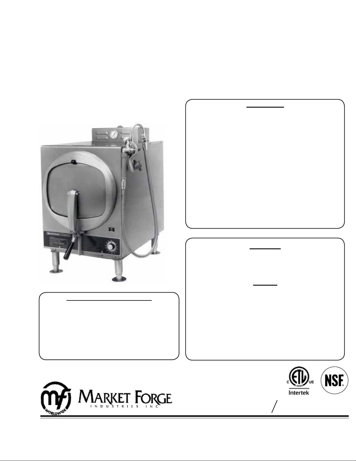
OWNER’S MANUAL
MARINE STEAM-IT
ELECTRIC COUNTER MODEL
MODEL: ● SB-ST-E
WARNINGS:
BE SURE TO GROUND THE COOKER CHASES FROM
THE GROUND TERMINAL BOX TO THE OUTSIDE
GROUND. REFER TO WIRING DIAGRAM C95-3914.
DO NOT OPEN THE DRAIN VALVE WHILE THE STEAM
COOKER IS OPERATING. PREMATURE OPENING MAY
RESULT IN SCALDING OF THE OPERATOR.
DO NOT LEAVE HAND ON HANDLE.
TO PREVENT SCALDING, THE OPERATOR SHOULD
KEEP HANDS OFF THE DOOR HANDLE WHILE EXCESS STEAM/VAPOR IS ESCAPING.
THE ELECTRIC POWER SUPPLY MUST BE DISCONNECTED PRIOR TO PERFORMING ANY MAINTENANCE/REPAIR WORK.
CAUTION:
HELP PREVENT PITTING OF THE ALUMINUM INTERIOR. DO NOT USE STRONG DETERGENT OR ABRASIVE CLEANERS.
NOTES:
TO ASSURE A PROPER PRESSURE SEAL, THE DOOR
DISTRIBUTION STATEMENT
THIS PUBLICATION IS REQUIRED FOR OFFICIAL USE FOR ADMINISTRATIVE OR OPERATING PURPOSES. DISTRIBUTION IS LIMITED
TO U.S. GOVERNMENT AGENTS ONLY. OTHER
REQUEST FOR THIS DOCUMENT MUST BE REFERRED TO COMMANDER, NAVAL SEA SYSTEMS COMMAND, SEA 09, WASHINGTON, DC
20362.
GASKET MUST BE FREE OF SOIL, SCALE AND
BREAKS.
SHOULD THE COOKING CYCLE BE STARTED WITH
INSUFFICIENT WATER IN THE COMPARTMENT, THE
SAFETY ACTION OF THE LOW WATER CUT-OFF WILL
SHUT THE UNIT DOWN. WHEN ADEQUATE WATER
(TOTAL: 6 QUARTS) IS ADDED TO THE CHAMBER,
THE COOKING CYCLE MAY BEGIN AGAIN.
FEDERAL SPEC S-C-1474B S6161-PA-FSE-010-/38379
TYPE SC1474-3106MA1 0910-LP-436-6200
44 Lakeside Avenue, Burlington, Vermont 05401 USA
Telephone: (802) 658-6600 Fax: (802)864-0183
www.mi.com PN 14-0299 Rev B (12/15)
© 2015 - Market Forge Industries Inc.
Page 2

S6161-PA-FSE-010-/38379
0910-LP-436-6200
DISTRIBUTION STATEMENT:
THIS PUBLICATION IS REQUIRED FOR OFFICIAL USE FOR ADMINISTRATIVE OR OPERATIONAL PURPOSES. DISTRIBUTION IS LIMITED TO U.S. GOVERNMENT AGENTS ONLY.
OTHER REQUEST FOR THIS DOCUMENT MUST BE REFERRED TO COMMANDER, NAVAL
SEA SYSTEMS COMMAND, SEA 09, WASHINGTON, DC 20362.
TABLE OF CONTENTS
INSTALLATION
SERVICE CONNECTIONS..................................1
ELECTRICALLY OPERATED ............................. 1
CERTIFICATIONS ..............................................1
UNPACKING & ASSEMBLY ...............................1
ELECTRICAL CONNECTIONS ..........................2
TERMINAL BOX LOCATION (FIG. 1) ................. 2
INSTALLATION CHECK-OUT ............................2
INITIAL CONTROL SETTINGS ..........................2
COOKER CHECK-OUT ...................................... 2
SHUTDOWN PROCEDURE ...............................2
PRINCIPLES OF OPERATION
GENERAL ........................................................... 3
OPERATION SEQUENCE .................................. 3
PRELIMINARY PROCEDURES .........................3
WIRING DIAGRAM (FIG. 2) ................................4
HOSE ASSEMBLY (FIG. 3) ................................ 5
PREHEATING ..................................................... 6
FACTS ON PARADE .......................................... 6
RECOMMENDED COOKING TIMES ................. 7
THE FLUE ..........................................................10
TO REMOVE THE FLUE .................................... 10
STEAM GAUGE .................................................10
STEAM TRAP ...................................................... 10
HOW IT WORKS ................................................10
TROUBLE TEST AND REMEDIES .....................10
FLUE REMOVAL ITEMS (FIG. A) ....................... 10
MAINTENANCE
PREVENTIVE MAINTENANCE .......................... 11
DOOR ASSEMBLY ............................................. 11
GASKET REPLACEMENT .................................11
DOOR SEAL TENSION ADJUSTMENT .............. 12
DOOR LIFT SPRING REPLACEMENT .............. 12
STEAM EXHAUST VALVE & TRAP
REPLACEMENT ................................................. 12
DAILY CLEANING ..............................................12
WEEKLY CLEANING .......................................... 12
CLEANING EXHAUST SILENCER .....................13
CLEANING TROUBLE-SHOOTING GUIDE
(STAINLESS STEEL) ..........................................13
ILLUSTRATED PARTS LIST
COOKER COMPARTMENT (FIG. 7) .................. 14
DOOR HANDLE ASSEMBLY (FIG. 8) ................ 17
THE COOKER DOOR ASSEMBLY .................... 18
DOOR ASSEMBLY (FIG. 9) ................................ 18
FULCRUM & DRAIN ASSEMBLY ....................... 18
ROLLER ASSEMBLY .......................................... 18
OLD STYLE FULCRUM & DRAIN
ASSEMBLY (FIG. 10) .........................................19
NEW STYLE FULCRUM & DRAIN
ASSEMBLY (FIG. 11) .......................................... 19
SAFETY VALVE .................................................. 19
CHECKING SAFETY VALVE .............................. 19
EXHAUST VALVE (FIG. 12) ...............................20
NEW EXHAUST VALVE, BUILT AFTER
JULY 1983 (FIG. 13) ............................................ 21
TROUBLE-SHOOTING
OLD STYLE BUILT PRIOR TO
SEPTEMBER 1980 (FIG. 14) .............................22
ELEMENT CONTROL SWITCH .........................22
HOW IT WORKS ................................................22
DIAL ADJUSTMENT ........................................... 22
NEW STYLE BUILT AFTER
SEPTEMBER 1980 (FIG. 15) .............................22
RECALIBRATING ELEMENT CONTROL
SWITCH .............................................................. 22
PRESSURE CONTROL SWITCH
(BARKSDALE) .................................................... 22
OPERATING PRESSURE ADJUSTMENT
(BRAKSDALE) .................................................... 22
RECALIBRATING PRESSURE CONTROL
SWITCH .............................................................. 23
LOW WATER CUT-OFF .....................................23
HOW IT WORKS ................................................23
TIMER ................................................................. 23
TROUBLE TEST & REMEDIES .......................... 23
TIMER CONTROL SWITCH ................................ 23
HOW IT WORKS ................................................23
DIAL ADJUSTMENT ........................................... 23
RECALIBRATING TIMER CONTROL
SWITCH ...............................................................23
PILOT LIGHT ...................................................... 23
TROUBLE-SHOOTING GUIDE .......................... 24
i
Page 3
INSTALLATION
SERVICE CONNECTIONS
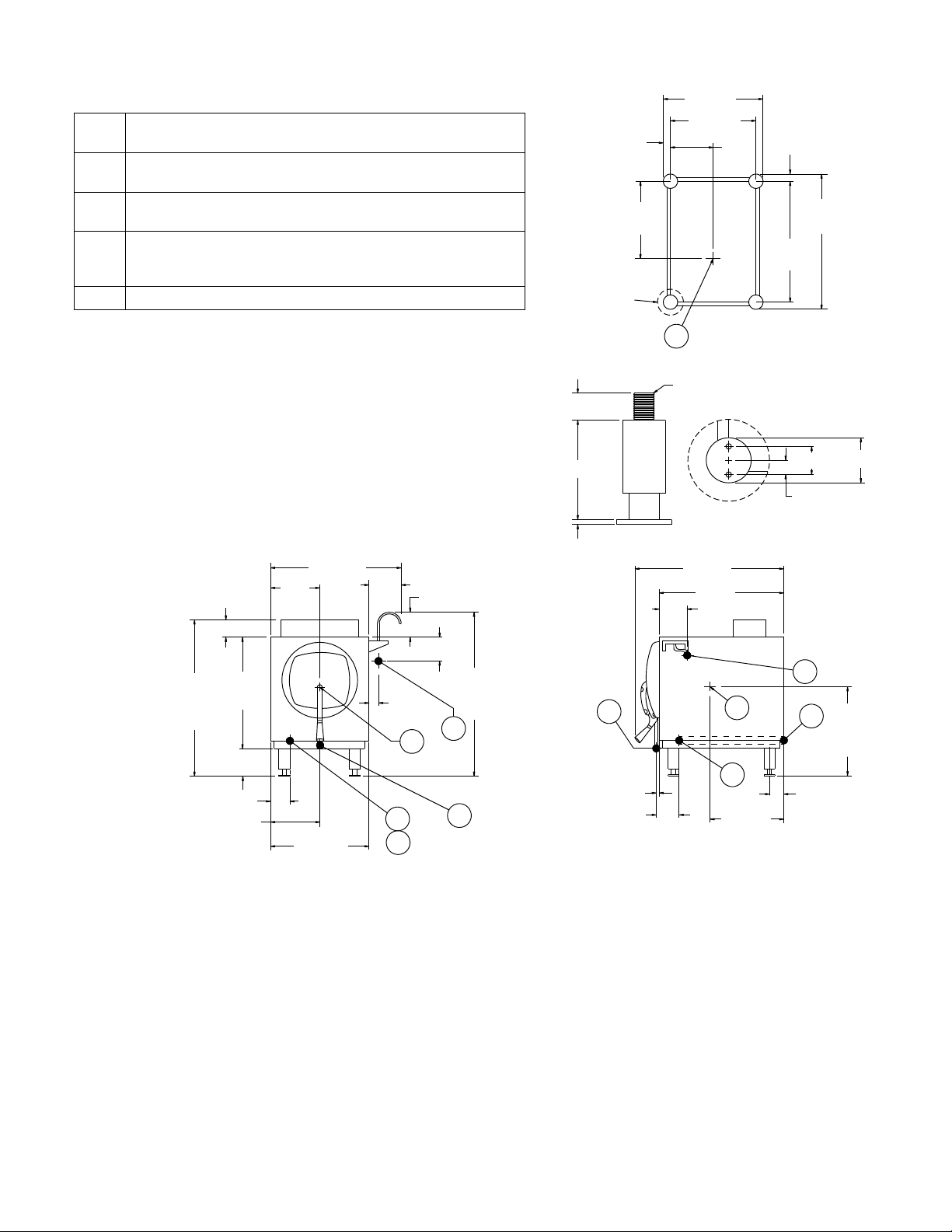
EC Electrical Connection - Connection for incoming power supply
wires on terminal block
EP Power Supply - 1-1/4” threaded access hole for power supply wires.
Use wire suitable for at least 90°C. Nominal amps per line.
D Drain - 1/2” 13mm O.D. tubing. Air break required for drain connec-
tion supplied by others
CW Cold Water - 3/8” 10mm O.D. tubing connection to fill hose. Cold
water line shall have a max of 50 PSI 3.5kg/cm2 and a min of 25 PSI
1.7kg/cm2 water pressure
CG Center of Gravity - with flanged feet
WATER SUPPLY
Good quality water feed is the responsibility of the owner. Water quality must be
within the following general guidelines.
TDS: 40-125 ppm Hardness: 35-100 ppm Chlorine: <0.2 ppm
Silica: <13 ppm Chlorides: <25 ppm
Chloramine: <0.2 ppm pH: 7.0 - 8.5
The best defense against poor water quality is a water treatment system
designed to meet your water quality conditions.
Appliance to be installed with backflow protection according to federal, state or
local codes.
DIMENSIONS ARE IN INCHES [MM]
23.75 [603]
3.25
[83]
9.88
[251]
5
[127]
4.38 1[20]
5.25 [133]
1 [25]
6 [152]
0.38 [3]
1.5 [38]
SEE
DETAIL A
MARINE FOOT
12.8
[325]
17.88 [454]
14.88 [378]
CG
BOTTOM VIEW
1/3-13THD
31.5 [800]
25 [640]
6.25
[158]
7.94
[378]
DETAIL A
1.5
[38]
21.13
[536]
24.13
[612]
2.13 [54]
1.06 [27]
CW
3 [76]
23 [584]
31.75 [806]
6 [152]
3.25 [83]
9.38 [240]
18.75 [480]
1.25 [32]
CG
EP
EC
CW
D
UNPACKING AND ASSEMBLY:
The Steam-It cooker is shipped in a carton with protective
padding and mounted on a wooden pallet. Carefully remove the carton, padding and the bolts securing the unit
to the wooden pallet. Inspect assemblies as follows:
1. Inspect unit overall for dents or deformations in stainless steel cabinet enclosures.
2. Make sure visible attaching hardware for all assemblies are not missing or damaged.
3. Inspect timer, indicator light, RESET switch and pressure gauge to see they are not damaged.
4. Install pan supports so that the horizontal keyhole
is at the rear of the cooking chamber and so that
the ange and embossments face the middle of the
chamber.
32.25 [819]
D
0.75 [19]
3 [76]
CG
Conduit
EC
14.38 [375]
EP
16.88 [429]
2.5 [69]
5. Install the set (4 each) of Marine anged feet (3” di-
ameter anged plates) so the steam cooker can be
mounted on a counter top (refer to spec sheet S-
2160) for anged feet details.
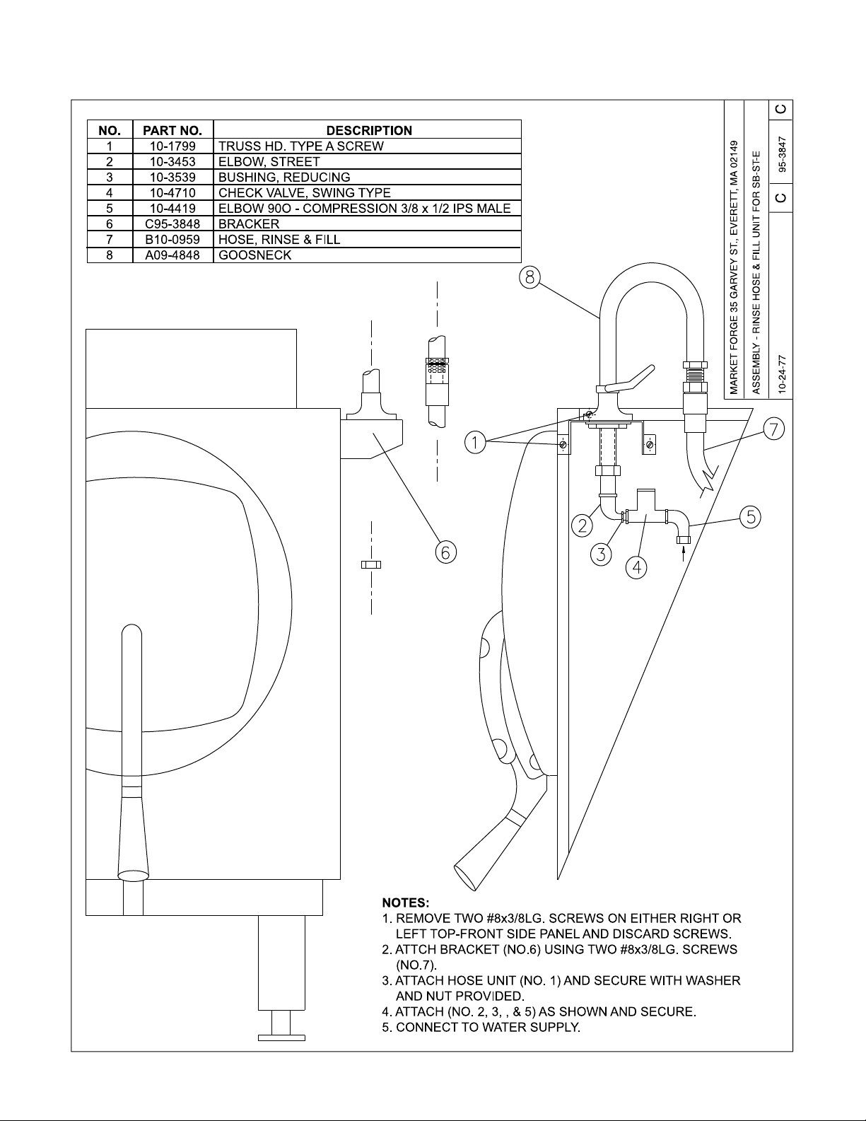
6. Install the part number 95-3849 rinse and ll hose unit
on the shipboard steam cooker. Refer to the enclosed
drawing C95-3897 Rev A for installation details.
NOTE: The cooker is carefully inspected and packaged
before leaving the factory. If there are missing components or unit is damaged, notify the carrier immediately.
Should repairs be required, a network of authorized service agencies is available to assist with prompt service. If
necessary, please contact:
1
Page 4

INSTALLATION
Product Service Department Market Forge
Toll Free: (866) 698-3188
Parts, Service and Availability Toll Free No.:
(888) 259-7076
custserv@mi.com, www.mi.com
The Model and serial numbers must be referenced when
corresponding with Market Forge. The data plate containing the serial number pertaining to the equipment is located on the front top of the cabinet.
ELECTRICAL CONNECTION:
The electrical connection may be made at the terminal
box located at the lower left side of the Steam-It removing
the small covering panel (see gure 1 below, and service
connections on previous page).
FIG. 1
REMOVE THIS
PLATE TO ELECTRICAL
CONNECTION
Power input is 12 kW at 208, 236 or 440 Volt, 60 cycle
A.C. Equipment is adaptable for single ir three phase. Unit
must be grounded. Wires should be brought up through
conduit at bottom of cooker (see wiring diagram c95-3914
Rev A (440V/6pH/60Hz) for instructions on making connection. Unit must be fused separately.
NOTE: Refer to the spec sheet, side 2 on page 2 for the
complete list and location of the required service connection and electrical details.
WARNING: BE SURE TO GROUND THE COOKER
CHASES FROM GROUND TERMINAL BOX TO AN
OUTSIDE GROUND. REFER TO WIRING DIAGRAM
C95-3914 REV A ENCLOSED. ALL RECOMMENDED
SAFETY PRECAUTIONS SHOULD BE OBSERVED
WHEN CONNECTION THIS UNIT TO THE EXISTING
POWER SUPPLY.
INSTALLATION CHECK-OUT:
After the Steam-It cooker is completely assemblies and
properly located with electrical supply connected, the
cooker must be given a thorough checkout before being
put into cooking operation.
Before making this checkout the operator must be thoroughly familiar with the operating procedures in Section
3 and with the function of each control described in principles of operation in Section 3. Reference Figure 4 for
identication of controls required in the following procedures. If the unit fails to perform as described below, con-
sult the trouble shooting guide for corrective action.
INITIAL CONTROL SETTINGS:
Before beginning cooker checkout procedures, perform
the following steps:
1. Check to see that the timer is off.
2. Visually check interior of cooking compartment and
remove any materials, papers, etc. Check to see that
pan supports are properly installed (refer to principles
of operation in Section 3, step 5) and secured.
3. Check pressure gauge to see that it registers zero
pounds.
COOKER CHECK-OUT:
The cooker checkout procedures are as follows:
1. Secure the drain valve (refer to operating instruc-
tions S-202B gure No. 4 on page 7) then pour six
(6) quarts of water into the steam-it cooking compartment through the door opening.
WARNING: BE CERTAIN THE DRAIN VALVE IS
CLOSED AND DO NOT OPEN IT WHILE THE UNIT
IS OPERATING, PREMATURE OPENING MAY RESULT IN’ SCALDING OF’ THE OPERATOR.
2. Close the door and lock in position by placing the
tongue of the door lock under the roller on the drain
casting and pressing downward until door lock comes
to a rm stop. This lock makes the initial seal. (When
steam pressure builds up in the compartment it will
force the door to a tighter closed position.)
3. Turn the Steam-It en. by setting the timer to the desired cooking time. Observe pressure increase indicated by pressure gauge.
4. At the close of the preset cooking period, the timer
pointer will stop at the “0” position on the dial. This
will shut down the Steam-It and automatically open
the exhaust valve. The Buzzer will continue to sound
until the dial pointer is manually turned to the “OFF”
position.
5. Observe that the indicator light goes out when timer is
at the “O-minute” position. Check the pressure gauge
to see that the pressure reads zero. The door will not
open while there is steam pressure working against it
from wi thin the cooking compartment. The door must
be kept locked until the cooking cycle has completely
nished, then the door opened to allow vapor to clear.
Shut off gas supply by closing the gas shutoff valve.
SHUTDOWN PROCEDURE:
No special shutdown procedures are required with the exception that the door is left open, timer must be in the OFF
position and the gas supply valve closed, (consult local
codes for daily shut-off requirement.
NOTE: Before using the Steam-It for cooking, it is recommended that checkout operations be performed 2 or 3
times in order to determine that. it is working properly and
to insure cleanliness of the cooking compartment.
2
Page 5

PRINCIPLES OF OPERATION
PLEASE READ CAREFULLY THE FOLLOWING INFORMATION AND THE OPERATING INSTRUCTIONS ON
THE FOLLOWING PAGES.
CAUTION: The model SB-ST-E Steam-It pressure
cooker cylinder is constructed of a corrosion resistant alclad aluminum alloy. The protective properties of this material afforded to the interior portion of, the cylinder which
is exposed to water may be destroyed by allowing a lm
to form. Such a lm can be caused by salt. or other con-
taminants in the water. If the water supply is known to be
hard or corrosive, a source of treated water should be
used. Corrosion may also occur if water is not drained
daily. Do not use distilled water.
NOTE: Market Forge will not be responsible for damage
resulting from the use of hard or corrosive water, from
failure to drain the unit daily, or from inadequate cleaning
procedures.
GENERAL:
The model SB-ST-E Marine Electric Steam-It pressure
cooker (15 PSI operation) consists of one (1) cooking compartment into which pans of food product are
loaded through an inwardly opening door. The self-con-
tained cooker is tted with electric heating elements for
440V/3PH/60HZ operation (16 amps) rated at 12KW impute
OPERATION SEQUENCE:
With water placed in the Steam-It to the recommended
six quart level and the door rmly locked to make a tight
seal, a cooking cycle will automatically be performed with
the act of setting the timer to the length of cooking time
desired. The automatic sequence of operation is:
STEP 1 Upon setting the timer, a current ows to: The
exhaust valve solenoid, activating it to close the exhaust
valve: The element pressure control switch, which relays
a current ow to the contactor coil causing the contactor to close and direct electricity to the heating elements:
The cooking cycle light, which remains in circuit while the
heating elements are on.
STEP 2 As steam is produced within the cooking cylinder,
trapped air escapes through the steam trap. The steam
trap is induced to close thermostatically when live steam
fully replaces the trapped air passing through it. Freeventing will automatically cease and cooking cylinder will
become steam-tight. A build-up of cooking cylinder steam
pressure will occur.
STEP 3 When the steam pressure build-up reaches 10
PSI, the timer control switch will activate the timer to start
its timing cycle.
STEP 4 When the steam pressure build-up reaches 14
PSI, the element control switch will cut off the current ow
to the contactor, causing it to open and cut off electricity
to the heating elements. When cooling causes the pressure to drop to 13 PSI, the element control switch will
again activate the contactor to close and restore the ow
of electricity to the heating elements. Thus, by controlling
the contactor to open and close intermittently, the element
control switch, in effect, maintains the cooking cylinder
steam pressures between 13 and 14 PSI.
STEP 5 (Timer reaches “Zero” position) When the timer
reaches “Zero” (the end of the cooking cycle), a circuit
is completed to the buzzer allowing it to sound while the
circuit t to the pilot light is broken. The steam exhaust
valve will open and the cooking chamber is automatically
exhausted of steam. The buzzer will continue to sound
until the timer knob is turned to the “Off” position. The
door will not open while there is steam pressure working
against it from within the cooking cylinder. The door must
be kept locked until the cooking cycle has completely nished, then open the door, allow a second or two for the
vapor to clear and remove the foods.
PRELIMINARY PROCEDURES:
1. Ensure that electric supply is connected and operating at until See Installation Instructions.
2. Close drain valve (g. 4, No. 3) by turning valve handle Clockwise.
3. Hang pan supports (g. 4, No. 2) on pan support
studs (cylinder side walls). The horizontal keyhole
on the support should be at rear or compartment and
vertical keyhole near front.
4. Pour approximately six quarts of water directly into
Steam-It cylinder.
NOTE: In geographical locations where a high amount
or lime and alkaline (salt-lime substance) deposits are
present in water Supply, add two tablespoons or vinegar
directly into six quarts of water in Steam-It compartment
prior to starting cooking cycle. It more water is added to
maintain required level, an occasional table Spoon of vinegar may be added as well, in order to compensate for
new mineral deposits fresh water.
CAUTION: A high degree or mineral salts in water can
cause pitting of cooking compartment unless above directions (See NOTE) are followed; the cooking compartment thoroughly cleaned and drained each night; and the
door left open. Also, go not scour cylinder With abrasive
cleanser.
WARNING: DO NOT OPEN DRAIN VALVE WHILE
UNIT IS OPERATING. PREMATURE OPENING MAY
RESULT IN SCALDING OF OPERATOR.
3
Page 6
PRINCIPLES OF OPERATION
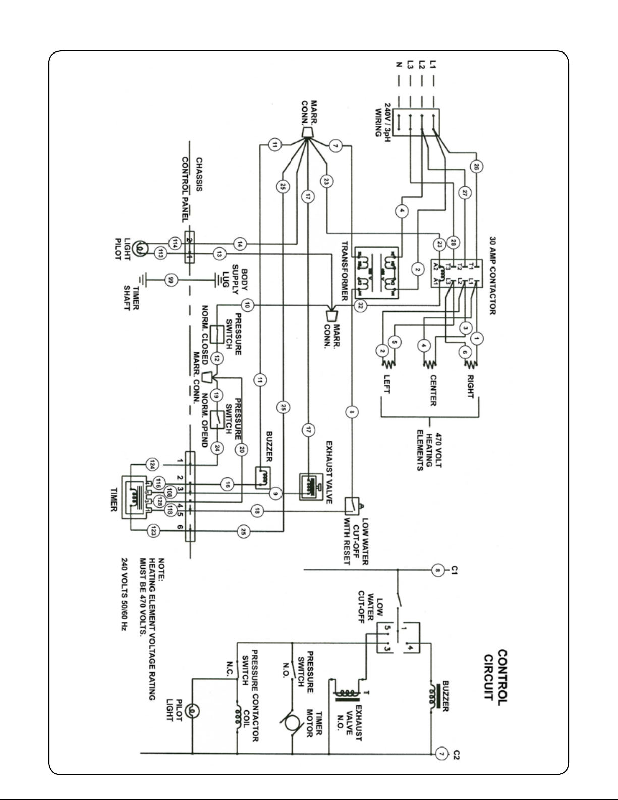
FIG. 2
4
Page 7
PRINCIPLES OF OPERATION
FIG. 3
5
Page 8
PRINCIPLES OF OPERATION
PREHEATING:
Before each Initial operation of cooker and at any time
when compartment is cold, a 5 to 8 minute preheating
period is required. To preheat cooking compartment. Proceed as follows:
1. Close door and lock in position by placing door handle tongue (Fig. 4 No. 4) under roller on drain casting
(Fig. 4 No. 5) press downward on door handle until
door is secured
2. Set minute timer (Fig. 4 No. 7) to 5 minutes by turning
past 10 and back to 5 to ensure proper setting. Indicator light will come on.
3. When preheating is ended (approximately 5 minutes)
and buzzer sounds. turn timer to OFF and allow pressure to return to 0 PSI on pressure gauge (Fig. 4 No.
8).
4. Open compartment door slightly by pulling up on latch
handle (g. 4. No. 6) to allow remaining vapor to escape before raising door to full open position.
WARNING: DO NOT LEAVE HAND ON HANDLE
WHILE EXCESS VAPOR IS ESCAPING. SCALDING OF
HAND MAY RESULT.
shut the unit down. When the required amount of water is added, the unit will be operational again after
the LOW WATER CUT-OFF BUTTON is pressed.
However, if the unit does not start after pressing the
reset button, more time will be needed before the reset button starts the unit. Should a cooking cycle be
interrupted by the low water cut off, the food in the
process of cooking will be affected. Proper compensation should be made for cooking already performed
and a new cook cycle determined. Clean the unit
thoroughly at the end of each day the cooker is used.
Ensure that the cylinder is left dry and the compartment door is left open.
Once the preheating cycle is completed, the cooker compartment may be loaded. The following procedures should
be followed:
1. Insert the pans of food into the pan support located
on the right and left side of the cylinder.
2. Close the door and lock in position by placing the
door handle tongue under the roller on the drain cast-
ing (refer to gure 4). Press downward on the door
handle until the door is secured.
3. Set the timer for the desired cooking time (refer to
Facts on Parade) by timing the timer past the desired
setting and then back. NOTE: The timer will not start’
until the unit is at a minimum of 9 PSI as indicated on
the pressure gauge.
4. At the completion of the required cooking cycle,
steam will automatically exhaust. When the pressure
reaches zero PSI on the pressure gauge, the cooker
compartment door can be released by pulling on the
door latch handle. The operator should allow a few
seconds for the remaining vapor to leave the cylinder before completely opening the door. To stop the
buzzer, turn the timer to the OFF position.
5. The next step is to remove the cooked food, add
any desired seasoning and transfer it to - the serving area. If perforated pans are used, they should be
underlined with a solid pan.
6. Check the’ water level in the cooker before starting
‘another cooking cycle. The water should be at the
six quart level. NOTE: If the unit is operated with an
insufcient amount of water the low water cut-off will
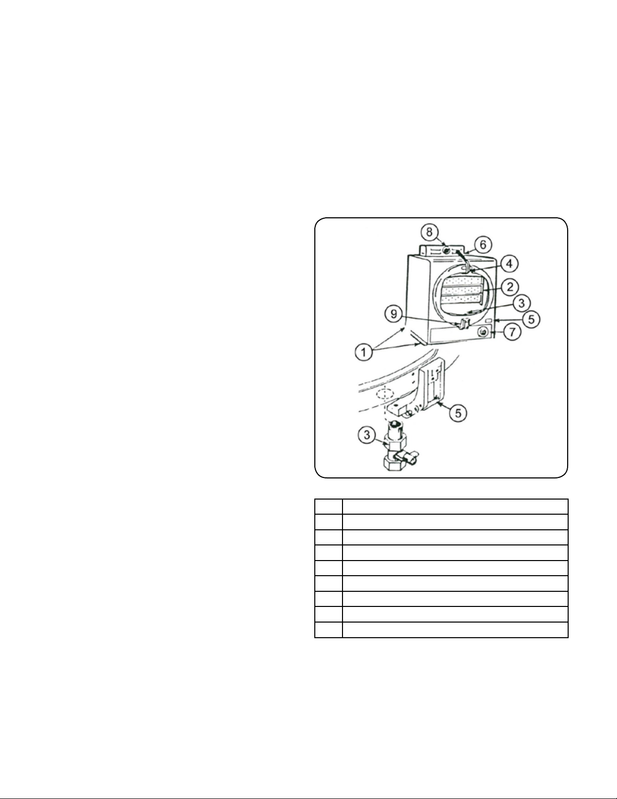
FIG.4
NOTE:
WATER RETAINER & SPRAY HOSE NOT SHOWN.
1 Electrical Connection Box
2 Pan Supports
3 Drain Valve
4 Door Handle Tongue
5 Roller on Drain Casting
6 Door Handle
7 Timer
8 Pressure Gauge
9 Low Water Cut-off Reset Button
FACTS ON PARADE:
1. All foods, except cakes and pastry, can be cooked in
a steam cooking unit.
2. Steam cooked meals have greater nutritional value
since they retain most of their vitamins and minerals.
3. Because foods are cooked faster by the higher temperatures of steam cooking, they can be prepared
closer to serving time, insuring maximum freshness.
6
Page 9

PRINCIPLES OF OPERATION
4. Steam cooked food has a higher percent yield - more
portions per dollar spent.
5. The principle upon which the steam cooker is based
can be likened to the domestic pressure cooker.
6. The principle upon which the steam jacketed kettle is
based can be likened to the domestic double boiler.
7. Food may be served from the same pan in which it
is steam cooked, thus reducing food breakage since
there is no extra handling or transferring of food from
cooking pans to serving pans. It also reduces pot,
washing tasks.
8. Some important advantages of steam cooking are: labor saving, reducing operating costs, space saving
and the lifting of heavy stock pots is eliminated.
9. Rice and spaghetti products, if thoroughly wet at
the start of the cooking process, are very easily prepared.
10. Foods such as potatoes, poultry, seafood and some
meats may be blanched in the steam cooker, thus reducing the total cooking time and grease absorption.
11. Fuel is used only when the steam cooking unit is in
operation.
12. The steam cooker will loosen foods burned on pans
making washing easier.
13. Solid pans are recommended when liquid is to be retained and perforated pans when the liquid is not to
be retained.
14. Eggs may be cooked out of the shell if they are to be
chopped which eliminates peeling after steaming.
15. Frozen or stale bread may be readied for serving with
a small amount of steam.
16. Meats may be sautéed in the kettle before any liquid
is added. Sautéing seals in the meat juices and helps
to retain avor.
17. The steam cooker can be opened during the cooking
period (by rst releasing the steam pressure) to add
or remove items. If any time is lost, an adjustment
may be made on the timer.
18. All frozen foods must be thoroughly defrosted in order
to retain the most satisfactory results.
19. Steam cooking information, including recommended
pan size and type, weight per pan, cooking times and
pan yields are given on the following pages of this
bulletin.
RECOMMENDED COOKING TIMES:
Approx.
Recommended
12” x 20”
Food Item
VEGETABLES, FROZEN, DEFROSTED
Asparagus,
Spears 2.5” 65mm 5# 2.3kg12-3
Beans, Green
Regular 2.5” 65mm 5# 2.3kg12-3
Breans, Green
French Cut 2.5” 65mm 5# 2.3kg12-3
Lima Beans 2.5” 65mm 5# 2.3kg12-3
Broccoli 2.5” 65mm 4# 1.8kg12-3
Brussels,
Sprouts 2.5” 65mm 5# 2.3kg12-3
Carrots,
Diced 2.5” 65mm 5# 2.3kg12-3
Cauliower 2.5” 65mm 5# 2.3kg12-3
Corn 2.5” 65mm 5# 2.3kg12-3
Peas 2.5” 65mm 5# 2.3kg12-3
* All portions are equivalent to approximately 1/2 cup cooked.
Perforated Pan
Raw
Weight
Per Pan
Pans
No.
of
Approximate
Timer
Setting
in
Minutes
7-8
8-10 23-25
7-8
8-10 23-25
7-9
9-10 23-25
6-7
7-8 23-25
5-6
6-7 18-20
6-7
8-10 23-25
5-6
7-9 23-25
7-8
8-10 23-25
5-6
7-8 23-25
2-3
4-5 23-25
No. Cooked
2oz. (55g)
Servings
Per Pan*
7
Page 10

PRINCIPLES OF OPERATION
Recommended
12” x 20”
Food Item
VEGETABLES, FRESH
Beans, Wax
Green 2.5” 65mm 6# 2.7kg12-3
Broccoli,
1/2” - 3/4” Stalk 2.5” 65mm 6# 2.7kg12-3
Cabbage,
Cored - 1/4, 1/6 of head 2.5” 65mm 5# 2.3kg12-3
Carrots,
Sliced 2.5” 65mm 9# 4.1kg12-3
Cauliower 2.5” 65mm 6# 2.7kg12-3
Corn on Cob,
Husked 2.5” 65mm 1 dozen12-3
Potatoes,
French Fry Cut 2.5” 65mm 10# 4.5kg12-3
Potatoes,
Regular Cut 2.5” 65mm 10# 4.5kg12-3
Spinach,
Cut and Cleaned 4” 100mm 3# 1.4kg12-3
Squash,
Summer, 1” Sliced 2.5” 65mm 7# 3.2kg12-3
Squash,
Winter Diced 2.5” 65mm 9# 4.1kg12-3
Turnip,
Diced 2.5” 65mm 5# 2.3kg12-3
Perforated Pan
Approx.
Raw Weight
Per Pan
No.
of
Pans
Approximate
Timer
Setting
in
Minutes
4-6
7-8 30-35
4-5
5-6 25-30
7-9
10-12 12-20
6-8
10-12 35-40
5-6
6-7 30-35
5-6
6-8 12
7-9
10-12 50
13-15
17-19 50
1-2
2-3
5-7
8-10 30-35
7-9
10-12 30-35
10-15
15-20
No. Cooked
2oz. (55g)
Servings
Per Pan*
4 oz. - 110g
10-12
4 oz. - 110g
20-25
VEGETABLES, CANNED
Canned,
Vegetables 2.5” 65mm 7.5# 3.4kg12-3
MISCELLANEOUS
Eggs,
Out of Shell 2.5” 65mm 4 dozen12-3
Rice,
1 Gallon Water - 3.78 lts 4” 100mm 4# 1.8kg12-3
Spaghetti,
1.5-2 Gallons Water - 5.7-7.6 lts 4” 100mm 3# 1.4kg12-3
* All portions are equivalent to approximately 1/2 cup cooked.
8
4-5
5-7 26-30
3
3-4
17-20
21-25
17-20
21-25
60/3oz. - 85g
Portions
40-45/4oz. -
110g Portions
48
48
Page 11

PRINCIPLES OF OPERATION
Approximate
Approx.
Recommended
12” x 20”
Food Item
MEAT - POULTRY - FISH
Chicken, Cut-Up
Blanched 2.5” 65mm 8# 3.6kg
Chicken,
Whole 4” 100mm
Fish,
Fillets 2.5” 65mm 3# 1.4kg
Fowl,
Whole 4” 100mm
Frankforts 2.5” 65mm 5# 2.3kg
Hamburgers,
3oz. - 85g 2.5” 65mm 5# 2.3kg
Lobster,
1# Size - 450g 2.5” 65mm 10# 4.5kg
Meatballs**
1oz. Size - 28g 2.5” 65mm 6# 2.7kg
Meatloaf** 2.5” 65mm 15# 6.8kg
Pork Chops,
loin, 4oz. - 114g with Bone 2.5” 65mm 6# 2.7kg
Sausages,
10 per pound - 45g each 2.5” 65mm 6# 2.7kg
Turkey,
on Carcass 4” 100mm
Turkey,
off Carcass 2.5” 65mm
* All portions are equivalent to approximately 1/2 cup cooked.
** Raw weight for meatballs and meatloaf includes and extenders and yields 2 oz. - 56g protein plus extenders for
3 oz. - 85g total portion.
Perforated Pan
Raw Weight
Per Pan
(3)
4# 1.8kg
(2)
5# 2.3kg
20-
22# 9-10kg 1 75-90
10-
4.5-
12#
50.4kg12
No.
of
Pans
1
2-3
1
2-3
1
2-3
1
2-3
1
2-3
1
2-3
1
2-3
1
2-3
1
2-3
1
2-3
1
2-3
Timer
Setting
in
Minutes
10-15
15-20
35-40
45-50
7-8
8-10
40-45
45-60
1-2
2-3
8-10
12-15
3-6
5-8
15-17
18-20
25-30
30-35
15-20
20-25
14-16
17-19
40-45
45-50
No. Cooked
2oz. (55g)
Servings
Per Pan*
15-20
Protein
25-30
Protein
12-15
Protein
20-25
Protein
35-40
Protein
20-25
Protein
10 - 1#
450g
20-25
Protein
50-60
Protein
24
Protein
18-20
Protein
50-60
Protein
55-65
Protein
9
Page 12

PRINCIPLES OF OPERATION
THE FLUE: (FIG. A)
The Flue serves as a protection shield for the Steam
Trap (B), safety Valve (A), Exhaust Valve (D), as well as
8 front-facing mount for the Steam Gauge (E). ks servicing 0’ these parts may at times require the removal of the
ue. an exploded view drawing is provided to show their
proper relative positions within the ue and the method of
their assembly to the cooking cylinder.
TO REMOVE THE FLUE: (FIG. A)
1. Unscrew and remove the exhaust silencer (F).
2. Detach the 3/16” copper tube connector (C) from the
Steam Gauge (E) at the ferrule nearest the steam
gauge. Then, remove the copper tube entirety by
freeing It at the other ferrule.
3. Apply inward pressure at either sides of the Flue at
points (1) and (2) with a screwdriver. This will collapse
the side walls slightly to allow the small uted sections
0’ sheet metal to clear the edges of the ue opening
provided in the outer Shell of the Steam-it. With the
restrictions of the utes removed, the Flue may then
be lifted up over the pans it houses.
4. To replace the Flue, reverse the above steps.
TROUBLE TEST AND REMEDIES:
The rst indication of defective steam trap operation will
usually be evidence by uneven cooking. If working properly, the steam temperature will be even and cooking will
be uniform through the cooking compartment. Trouble
may occur either through premature closing of the steam
trap before all the cold air has been exhausted or by its
failure to close sufciently to enable a proper steam pressure build-up. Either case warrants the replacement of
the steam trap.
STEAM GAUGE:
Located at the top rear of the steam-it and mounted into
the forward face of the ue for visibility, the steam gauge
registers the pressure within the steam-it cooking chamber. To replace this unit it is necessary to disconnect the
3/16” copper tube connector and remove the two nuts
holding the gauge framework in place.
STEAM TRAP:
The steam trap is located within the ue at the top rear
of the steam-it. It has the very important automatic, dual
function of exhausting all cold air from the cooking compartment and making a suitable seal to allow a pressure
build-up of live steam during the cooking cycle. Failure of
this unit to operate properly will result in uneven cooking.
HOW IT WORKS:
With the introduction of steam into the cooking compartment, the cold air escapes through the steam trap. When
sufcient generated steam displaces the cold air, it passes through the steam trap, and the thermostatic element
becomes heated and expands to “make” a seal against
the seat. This action encloses the live steam within the
cooking compartment and allows a steam pressure buildup to occur.
FIG. A FLUE REMOVAL ITEMS:
A. Safety Valve
B. Steam Trap
C. 3/16” Copper Tube Connector
D. Exhaust Valve
E. Steam Gauge
F. Exhaust Silencer
1 & 2 Flue Release Pressure Points
10
Page 13

MAINTENANCE
PREVENTIVE MAINTENANCE:
This section contains both preventive and corrective
maintenance information. Preventive maintenance may
be performed by maintenance personnel at the establishment in which the cooker is installed. It is recommended
that user personnel never attempt to make repairs or replacements to the equipment without the assistance of
authorized service agent.
CAUTION: UNDER NO CIRCUMSTANCES SHALL
HARDWARE (OR PARTS) BE REPLACED WITH A DIFFERENT LENGTH, SIZE OR TYPE OTHER THAN SPECIFIED IN THE PARTS LIST. THE HARDWARE USED
IN THE STEAM-IT COOKER HAS BEEN SELECTED
OR DESIGNED SPECIFICALLY FOR THEIR APPLICATIONS AND THE USE OF HARDWARE OTHER THAN
THOSE SPECIFIED MAY DAMAGE THE EQUIPMENT
AND WILL VOID ANY WARRANTY.
WARNING: THE ELECTRIC POWER SUPPLY MUST
BE DISCONNECTED PRIOR TO PERFORMING REPAIR/SERVICE WORK ON THE MODEL SB-ST-E ELECTRIC STEAM-IT PRESSURE COOKER DISASSEMBLY
AND CLEANING
bly Figure 15.
GASKET REPLACEMENT:
The door gasket (Figure 16, item 6) is readily replaced
by rst removing the door assembly from the cooking
compartment as explained in disassembly and cleaning
The door assembly must be removed from the cooker
compartment for weekly cleaning. Though no tools are
needed, care in following procedure is necessary to insure. that the door will pass through the compartment
opening.
1. With cooking compartment door open, lift pan supports up and forward to disengage from mounting
studs. Remove from compartment. .
2. Disengage left and right ends of door seal spring by
counter-acting the force of the door lift spring with one
hand while disengaging studs with the other hand.
3. Push door lift springs to the rear and off studs.
4. Rotate the door assembly out through the door open-
ing, door handle rst.
5. Inspect door gasket for cleanliness and wear. If food
soil has become lodged behind the gasket or the gasket is torn, push it off perimeter of door and clean with
mild detergent-water solution, or replace as needed.
A gasket which is stuck to the door is easily removed
by rst soaking the entire door in hot soapy water. To
assure a pressure seal, the gasket must be cleaned
of soil and scale, and be free of breaks.
6. Replace gasket on door and reassemble door assembly in compartment. Open and close door several
times to check for correct operation and tight seal of
door in closed position.
FIG. 5
FIG. 6
instructions. The worn gasket is removed in the same
manner as described for cleaning and a replacement sub-
stituted. A new gasket which is difcult to stretch onto the
door can be made pliable by rst soaking it in hot soapy
water. Remounting the door in the compartment completes the replacement.
DOOR ASSEMBLY:
The door assembly consists of the door latch and the latch
fulcrum assembly. All parts are replaceable as shown in
gure 17, Door Assembly Figure 16, Door Handle assem-
NOTE: The critical function of the makes it imperative that
the in good condition. For this is recommended that at
least gasket be kept at all times door seal gasket be reason it one spare.
11
Page 14

MAINTENANCE
DOOR SEAL TENSION ADJUSTMENT:
An adjustment screw is built into the door anchor and fulcrum assembly to allow compensation for normal variation in gasket thickness caused by wear. The adjustment
screw is shown in Figure 6. If steam escapes from around
the door, sealing tension against the door opening can
be increased by loosening the 1/4-20 jam nut and turning the socket head adjustment screw counterclockwise
with an allen wrench. Installation of a replacement door
gasket may result in excessive door latching tension and
require clockwise adjustment of the screw. Trial and error
will achieve the screw adjustment which both seals the
door against the compartment opening yet allows door
latching with only moderate force applied to the handle.
The nal position is set by holding the cap screw with an
allen wrench while tightening the 1/4-20 jam nut.
DOOR LIFT SPRING REPLACEMENT:
Should either spring become damaged, it is necessary to
replace both left and right springs as a set (Figure 16). The
door assembly is removed from the cooking compartment
as explained in the Disassembly and Cleaning Instructions. Springs are installed by removing spring bearings
(2), screws (1), and worn springs (3 and 4) and mounting
replacements. Springs are marked with tabs indicating
the left and right side replacement springs for installation
on the appropriate side as viewed from the front of the
compartment.
EXTERIOR PANEL REMOVAL:
Access to all internal plumbing assemblies is from the top
and front of the Steam-It cabinet. Whenever internal repairs or replacements are required, the applicable panels
must rst be removed. These parts are shown in Figure
14. The following procedure is required for removal of ex-
terior panels.
1. Raise the cooking compartment door.
2. Remove screws (7) in lower front panel (11) and timer
knob
3. Slide lower front panel (11) down from cylinder and
lift off.
4. To gain access to terminal block (for primary power),
remove screws (1) securing terminal box cover to
side panel.
3. Apply inward pressure at either side of the ue with
a screwdriver. This will collapse the side walls slightly
to allow the small uted sections of the sheet metal
to clear the edges of the ue opening provided in the
outer shell of the Steam-It. With the restrictions of the
utes removed, the ue may then be lifted up over the
components.
4. Replacement of safety valve, trap plumbing and
exhaust valve assembly (as required) may now be
made. The components of the steam exhaust valve
assembly.
CAUTION: IF THE WATER SUPPLY IS KNOWN TO
BE HARD OR CORROSIVE, A SOURCE OF THREADED
WATER SHOULD BE USED. CORROSION MAY ALSO
OCCUR IF WATER IS NOT DRAINED DAILY. DO NOT
USE DISTILLED WATER.
MARKET FORGE SB-ST-E MARINE STEAM-IT MUST
BE CLEANED ONCE A DAY!
DAILY CLEANING: Remove pan supports by lifting
the front up and off the stud. Pull back of pn support forward and off stud. Wash with mild detergent and water.
Rinse and dry throughly.
CAUTION: DO NOT USE STRONG DETERGENT OR
ABRASIVE CLEANERS. PITTING OF ALUMINUM INTERIOR WILL OCCUR.
WEEKLY CLEANING: Remove the door. Raise the
door to a fully open position and disengage the door spring
from each of the door spring studs. Do this by counteracting the force of the door lift spring with one hand while
working the end of the door spring off the door assembly with the free hand. Do this on both side of the door
assembly. When the ends of the door spring have been
completely freed from their respective door spring studs,
the door lift springs on either side of the door assembly
can easily be slipped off their studs. All Equipment is located on the top and at the back of the SB-ST-E Cooker
ONLY. Check the vavle. Lift the handle on valve when SBST-E is under pressure. Steam should escape.
NOTE: Dirty water may escape for a few seconds, but
then the steam should ow freely.
STEAM EXHAUST VALVE AND TRAP REPLACEMENT: The components of the steam ex-
haust valve assembly, trap, safety valve, silencer, pressure gauge and associated plumbing and hardware are
replaced by rst removing ue assembly and pressure
gauge. To remove ue assembly proceed as follows:
1. Unscrew and remove exhaust silencer.
2. Detach the 3/16” copper tube connector from the pressure gauge at the ferrule nearest the pressure gauge.
Then, remove the copper tube entirely by freeing it at
the other ferrule.
Steam trap should rst allow air to escape and then slowly close as all air is forced out of the compartment. The
sound of air escaping is quite noisy, but subsides once
steam pressure is built up and cooking takes place. If
steam trap does not close, it should be replaced. Exhaust
silencer must be cleaned by rinsing in mild detergent and
water or changed whenever clogged.
Your particular unit may be equipped with a different trap
- old style or new style. Replace steam traps will be of the
new style. Do this weekly if using new style.
12
Page 15

MAINTENANCE
CLEANING EXHAUST SILENCER:
The exhaust silencer should be removed and cleaned periodically. As the cooking chamber is exhausted of steam
through the silencer, impurities can build up from food particles. Cleaning should be frequent enough to prevent clogging to occur. For this reason, the exhaust silencer is made easily accessible and simple to remove.
To Clean:
1. Remove the one piece exhaust silencer from the unit by unscrewing it in a counterclockwise direction.
2. Clean the silencer by sloshing it in hot soapy water and rinse in clear water. if dirt has clogged the silencer presoak
it in an alkaline cleaning solution.
3. After cleaning, stand the silencer on edge to allow it to drain.
4. Screw it back into the elbow of the exhaust valve counterclockwise.
CLEANING TROUBLE-SHOOTING GUIDE (STAINLESS STEEL):
Routine Cleaning: Soap, ammonia or detergent with hot water. Clear water will rinse.
Overall “straw” color lm: Caused by water and detergent residue. Use mild phosphoric acid-type cleaner.
Stubborn spots, stains and
baked on splatter:
Heavy tinting, or heavy
discoloration:
Hard water spots, scale: Vinegar.
Grease and oil: 5% oxalic acid, 5% sulfamic acid, 5-10% phosphoric acid, dilac, oakite #33, texo 90,
Allchem concentrate, samae, cameo, coper cleaner, liquid or paste Nu-Steel or DuBois temp, gobbard’s or revere stainless cleaner, scouring powder (rinse thoroughly),
steel bright, lumin or zud.
Penny-brite, copper-brite, DubBois temp, tarnite, gobbard’s or revere stainless
cleaner.
texo 91, or organic solvents (acetone, bensene, alcohol, trichlorethane, cloroethane n.
u,).
NOTE: Clear water rinsing followed by wipe-down with soft cloth is recommended after all cleaning procedures.
These recommendations are based on tests and studies done by the Armco Reserch Center and
provided through the courtesy of American Iron and Steel, Institue’s Stainless Steel, Producer’s
Committee.
WARNING:
DO NOT HOSE DOWN UNIT AS IT CONTAINS ELECTRICAL COMPONENTS.
13
Page 16

ILLUSTRATED PARTS LIST
FIG. 7 Cooker Compartment
14
Page 17

ITEM FIG. 7 Cooker Compartment PART
NO. DESCRIPTION NO.
1 BASEPLATE ASSY - FIXED 95-3301
2 TRANSFORMER 440/480 V UNITS 10-5234
3 NO. 10 LOCKWASHER STAINLESS STEEL *
4 NO. 10-32 x 1/2” BINDING HD SCREW STAINLESS STEEL *
5 LEAD ASSY, TRANSFORMER 95-3394
6 PLUG BUTTON 10-3095
7 PLATE -TREM, STRIP SUPPORT 95-3289
8 COVER - TERM. BOX 95-3484
9 NO. 8-32 x 1/8” RD HD SCREW STAINLESS STEEL *
10 GROUND LUG 10-6969
11 CONNECTOR 95-3500
12 REDUCING WASHER 10-6967
13 JUNCTION BOX COVER 95-3489
14 TERM. STRIP SECTION 10-6962
15 TERM. STRIP END SECTION 10-6963
16 BASEPLATE SUB ASSY - MOVABLE 95-3302
17 CONTACTOR 280V, 50/60 Hz CYCLE, COMPLETE 10-5466
CONTACTOR 230/240V, 50/60 Hz CYCLE, COMPLETE 10-5467
18 COIL 208V, 50/60 Hz CYCLE 10-5470
COIL 230V, 50/60 Hz CYCLE 10-5471
19 LOW WATER CUT-OFF 10-5990
20 NO. 6-32 x 1/4” TRUSS HD SCREW STAINLESS STEEL *
21 CONNECTOR 10-6966
22 PRESSURE CONTROL - OPEN ON RISE 95-0998
23 PRESSURE CONTROL - CLOSE ON RISE 95-0999
24 NO. 10-32 x 1/2” RD SCREW STAINLESS STEEL *
25 ADAPTER - STRAIGHT 1/4” OD - 1/2” IPSM 10-2904
26 ADAPTER - TEE 1/8” IPS - 1/4” OD - 1/4” ODM 10-3426
27 REDUCING BRUSH 1/4-1/8 IPS 00-3652
28 TUBE 95-3305
29 TUBE - PRESSURE CONTROL 95-3304
30 UNION - COMPR. FITTING 1/4 OD 10-1154
31 TUBING - STEAM PRESSURE LINE 95-3387
32 TIMER, 60 MINUTE 95-3404
33 BRACKET, TIMER 95-3277
34 KNOB, DIAL 10-6307
35 BRACKET - PILOT LIGHT 95-3403
36 LOCK WASHER 10-2509
37 HEX NUT 10-32 10-2340
38 PILOT LIGHT 10-6669
39 EXHAUST SILENCER 10-4963
40 CAGE, ELECTRIC WIRE 95-0483
41 CONDUIT - NIPPLE 10-6964
42 SPEEDNUT 6-32 10-4110
43 WASHER 95-0463
44 NO. 10-32 x 1/8 HEX SOCKET HD CAP SCREW STAINLESS STEEL *
15
Page 18

45 DOOR HANDLE ASSY - COMPLETE 95-0144
46 DRAIN PLUG ASSY - COMPLETE 95-0154
47 HANDLE BUMPER 10-0226
48 NO. 8-32 x 1/8 BINDING HD SCREW TY ‘Z’ STAINLESS STEEL *
49 SAFETY VALVE 10-4636
50 STEAM TRAP 10-6156
51 ADAPTER 10-6158
52 OLD STYLE - EXHAUST VALVE 208V, 60 Hz CYCLE COMPLETE 95-0944
OLD STYLE - EXHAUST VALVE 230/480V, 60 Hz CYCLE COMPLETE 95-0945
OLD STYLE - EXHAUST VALVE 230V, 50 Hz CYCLE COMPLETE 95-0946
OLD STYLE - EXHAUST VALVE 208V & 230V, 50 Hz CYCLE COMPLETE 95-0946
52A NEW STYLE - EXHAUST VALVE (NOT SHOWN) N/A
NEW STYLE - EXHAUST VALVE 220/240V, 50/60 Hz 09-6545
NEW STYLE - EXHAUST VALVE 208V, 50/60 Hz 09-6536
53 NIPPLE, 1/8 IPS 10-3852
54 ELBOW, 1/8 IPS ST’D 90O 10-3851
55 BUZZER - COMPLETE 10-6665
56 FULCRUM & CRAIN ASSY 95-0115
57 5/16-18 x 1 1/2” SQ HD SCREW STEEL CAD. PL. *
58 5/16 FLAT WASHER, 1/8 ID x #16 GA ST’D STEEL CAD. PL. *
59 HEX NUT 5/16-18 ST’D STEEL CAD. PL. *
60 CONNECTOR, 1/8-90O 10-5036
61 FRONT LOWER PANEL ASSY 95-3388
62 NAMEPLATE PANEL 60 CYCLE 10-6595
63 NAMEPLATE PANEL 50 CYCLE 10-7096
64 ROD 95-0466
65 PAN INSULATION 95-0465
66 STUD 10-1937
67 PAN RACK ASSY - RIGHT SIDE 95-2545
68 PAN RACK ASSY - LEFT SIDE 95-2546
69 1/4 SHAKEPROOF INT. TOOTH LOCKWASHER STAINLESS STEEL *
70 1/4-20 x 3/4” RD HD SCREW STAINLESS STEEL *
71 1/4-20 x 1/84” HEX HD SCREW STAINLESS STEEL *
72 CASE - TOP FONT UPPER 95-3131
73 CASE - LEFT SIDE 95-3140
74 CASE - RIGHT SIDE 95-3141
75 CASE- BACK 95-3490
76 NO. 8 x 1/8” PHIL. TRUSS HD SCREW TY ‘A’ *
77 FLUE ASSY 95-3135
78 PRESSURE GAUGE 10-0883
79 TUBING PRESSURE GAUGE 95-3270
80 DOOR ASSY, COMPLETE 95-0124
81 BODY ASSY 208V & 236V 95-0478
BODY ASSY 470V 95-0479
82 RETAINER, WATER (NOT SHOWN) 91-2601
83 ASSY, HOSE FILL (NOT SHOWN) 95-3849
84 FOOT, FLANGED 4” (NOT SHOWN) 91-2449
* THESE PARTS ARE AVAILABLE AT LOCAL HARDWARE, PLUMBING AND ELECTRICAL OUTLETS. IF NOT
OBTAINABLE, SPECIAL PRICES WILL BE QUOTED BY MARKET FORGE UPON REQUEST.
16
Page 19

ILLUSTRATED PARTS LIST
FIG. 8 Door Handle Assembly
ITEM PART
NO. DESCRIPTION NO.
1 NO. 10-32 ACORN NUT 10-2318
2 #10 SHAKEPROOF LOCKWASHER 10-2514
3 LOCKING SCREW 10-1999
4 BEARING SPACER 95-0120
5 3/8” SHAKEPROOF LOCKWASHER 10-2517
6 DOOR LOCK KNOB 10-0050
7 DOOR HANDLE CASING 95-0134
8 1/4”-20 ACORN NUT 10-2359
9 DOOR HANDLE BEARING STUD 95-0658
10 DOOR HANDLE BEARING BRACKET 95-0659
11 1/4” SHAKEPROOF LOCKWASHER 10-2513
12 1/4”-20 x 5/8” RD HD SCREW * 10-1731
13 DOOR LOCK ASSY 95-3223
14 DOOR LOCK KNOB ASSY (ITEMS 1-6 PLUS 13) 95-0145
15 COMPLETE DOOR HANDLE ASSY (ITEMS 1-13) 95-0144
* OBTAIN AT LOCAL HARDWARE STORE.
17
Page 20

ILLUSTRATED PARTS LIST
THE COOKER DOOR ASSEMBLY
The door of the Cooker has been engineered to establish a positive method of sealing the steam pressure within the
cooking cylinder. As steam pressure builds up within the cylinder, the door seal will tend to become more positive.
However, the door should be adjusted to make a good initial seal between the door gasket and the door opening
without the added assistance of “internal cylinder steam pressures. With the simple action of securing the door handle
down in a locked position, the door gasket should be sufciently compressed against the door opening, all the way
around, to prevent any steam leakage from occurring.
ITEM FIG. 9 Door Assembly PART
NO. DESCRIPTION NO.
1 PIVOT SPRING BEARING 10-6765
2 DOOR LIFT SPRINGS - PAIR 10-2718
3 10-32 MACHINE SCREW 1/2” LONG 10-1776
4 DOOR GASKET 10-2666
5 DOOR & DOOR SPRING ASSY 95-3204
6 DOOR SPRING 95-0127
-- COMPLETE DOOR ASSEMBLY (ITEMS 1-6) 95-0124
FULCRUM & DRAIN ASSEMBLY:
The Fulcrum and Drain Assembly is located at the lower front of the cooking cylinder and furnishes a sturdy anchorage for the door locking system of the door handle. Also provided In this assembly is a means of adjustment for the
door seal. The drain port and drain plug provide a means of discharging accumulations of water from !.he cooking
cylinder.
ROLLER ASSEMBLY:
Built Prior to 10/85 (Items 5. 6. 7. 8. & 9.)
Built after 10/85 (Items 2. 8. 9. 13. & 14.)
The Roller Assembly must be kept free-rolling at all times. Should this assembly be allowed to become frozen due to
lack of lubrication undue strain will be put on the door handle and the fulcrum casting while the door is being locked.
Use only a dry lubricant such as graphite, as oil Of grease will tend to attract dirt to this area.
18
Page 21

ILLUSTRATED PARTS LIST
FIG. 10 Old Style Fulcrum & Drain Assy
ITEM PART
NO. DESCRIPTION NO.
1 FULCRUM & DRAIN CASTING 95-0116
2 1/4-20 x 3/8 HELICOIL 10-3111
3 1/4” SHAKEPROOF WASHER 10-2513
4 1/4-20 CAP SCREW, 1/8” LG. * 10-1790
5 10-32 ACORN NUT 10-2318
6 #10 SHAKEPROOF LOCKWASHER 10-2518
7 BRONZE BEARING 95-0198
8 BEARING SPACER 95-0120
9 10-32 MACHINE SCREW, 1.5” LG. 10-1999
10 ROLLER ASSY (ITEMS 5-9) 95-0149
11 1/4-20 MACHINE SCEW, 3/4” LG. * 10-1763
12 1/4-20 ALLEN SET SCREW 10-2087
13 1/4-20 JAM NUT 10-2358
14 1/4-20 x 3/8 HELICOIL 10-3116
-- COMPLETE FULCRUM ASSY
(ITEMS 1-14)
15 DRAIN PLUG HANDLE 95-0658
16 DRAIN PLUG 10-2227
17 1/4-20 ACORN NUT 10-2359
18 DRAIN & PLUG HANDLE ASSY
- COMPLETE
* OBTAIN AT LOCAL HARDWARE STORE.
95-0115
95-2604
FIG. 10
FIG. 11
FIG. 11 New Style Fulcrum & Drain Assy
ITEM PART
NO. DESCRIPTION NO.
1 1/4-20 x 3/8 HELICOIL 10-3116
2 10-32 MACHINE SCREW, 1 3/8” LG. 10-1999
3 1/4-20 FULCRUM NUT 10-2358
4 1/4-20 ALLEN SET SCREW 10-2087
5 1/4-20 x 3/8 HELICOIL 10-3111
6 1/4” SHAKEPROOF WASHER 10-2513
7 1/4-20 MACHINE SCEW, 3/4” LG. * 10-1763
8 BEARING SPACER 95-0120
9 BRONZE BEARING 95-0198
10 1/4-20 x 3/8 HELICOIL 10-3111
11 1/4” SHAKEPROOF WASHER 10-2513
12 1/4-20 CAP SCREW, 1/8” LG. * 10-1790
13 #10 SHAKEPROOF LOCKWASHER 10-2514
14 10-32 ACORN NUT 10-2318
15 FULCRUM & DRAIN CASTING 95-3850
16 BALL VALVE 10-1041
-- FULCRUM & DRAIN ASSY
(ITEMS 1-5)
* OBTAIN AT LOCAL HARDWARE STORE.
95-3992
SAFETY VALVE: The Safely Valve is set to automati-
cally relieve the cooking compartment of excessive pressure build-ups by opening at a point between 15 1/2 Ibs.
and 16 lbs.
CHECKING SAFETY VALVE: If the Safely Valve
should leak continually with a pressure build-up, or should
it cause an interruption of the Cooking cycle prematurely
(less than 15 1/2 Ibs. on the steam gauge), it must be
determined to be defective and be replaced. However,
the steam gauge should rst be checked for accuracy before making this determination. The steam gauge should
register absolute zero with no pressure in the cooking
cylinder. If the normal zero setting has advanced some
what through usage (a characteristic of steam gauges),
the amount of advancement from absolute zero must be
subtracted from its registered reading 10 determine the
true steam pressure.
19
Page 22

ILLUSTRATED PARTS LIST
ITEM FIG. 12 Exhaust Valve PART
NO. DESCRIPTION NO.
1 TEE ASSEMBLY 95-0756
2 BALL & PIN ASSEMBLY 95-0372
3 DIAPHRAGM BODY ASSEMBLY 95-2077
4 NO. 10 FLAT WASHER 3/16” ID x 1/2 OD x0.086 ( CAD. PI ) 10-2425
5 SPRING, COMPRESSION 10-4675
6 PIN, COTTER 1/16 x 1/2 STAINLESS STEEL 10-1663
7 SOLENOID BRACKET ASSEMBLY 95-0431
8 NO. 10-32 x 3/8” RD. HD. SREW ( CAD. PI ) 10-1759
9 NO. 10 LOCKWASHER ( CAD. PI ) 10-2505
10 1/4-20 x 3/8” RD. HD. SCREW ( CAD. PI ) 10-1701
11 1/4 LOCKWASHER ( CAD. PI ) 10-2500
12 CHANNEL 95-0755
13 PIN, ROLL 1/8 x 1-1/8” ( CAD. PI ) 10-1678
14 PIN, SOLENOID 95-0760
15 COIL - 208V, 60 CYCLE 10-6663
15 COIL - 208V, 50 CYCLE 10-6664
15 COIL - 230V, 60 CYCLE 10-6656
15 COIL - 230V, 50 CYCLE 10-6657
16 SOLENOID - 208V, 60 CYCLE, COMPLETE 10-6662
16 SOLENOID - 208V, 560 CYCLE, COMPLETE 10-6667
16 SOLENOID - 230V, 60 CYCLE, COMPLETE 10-6666
16 SOLENOID - 230V, 50 CYCLE, COMPLETE 10-6660
-- EXHAUST VAVLE - 208V, 60 CYCLE, COMPLETE 95-0944
-- EXHAUST VAVLE - 208V, 50 CYCLE, COMPLETE 95-0947
-- EXHAUST VAVLE - 230-480V, 60 CYCLE, COMPLETE 95-0945
-- EXHAUST VAVLE - 230V, 50 CYCLE, COMPLETE 95-0946
-- ASSEMBLY ( ITEMS 1 THRU 6 ) COMPLETE 95-3197
20
Page 23

ILLUSTRATED PARTS LIST
ITEM FIG. 13 NEW Exhaust Valve, Built after July 1983 PART
NO. DESCRIPTION NO.
1 ASSY PIPLIN EXHAUST, 208-240V, 50/60Hz C95-3996
2 HEAT DEFLECTOR PLATE C95-3990
3 TUBING, PRESSURE GAUGE A95-3270
4 PEM., CORN, BRASS 1/8 IPS x 3/16 OD 10-3361
5 90 DEGREE COMP., 1/8 IPS MALE 3/16 OD 10-3360
6 TEE REDUCING BRASS (EXSITING) 10-3432
7 NIPPLE, BRASS CHR. PL (EXSITING) 10-3420
8 MARR CONNECTOR 10-5143
9 PLUG, COUNTERSINK, 1/4 IPS BR. CHR. PL. P09-4843
10 PACKING CORRUGATED CARTON (8x8x6) 10-1643
11 SILENCER EXHAUST STEAM-IT A10-4963
12 EXHAUST VALVE ONLY 220-240V, 50/60Hz 09-6545
12 EXHAUST VALVE ONLY 208V, 50/60Hz 09-6536
21
Page 24

TROUBLE-SHOOTING
FIG. 14
ELEMENT CONTROL SWITCH: The element
control switch, located under the removable front lower
panel, just left of center, governs the ow of current to the
heating elements to maintain cylinder pressures at a near
constant 14 PSI.
HOW IT WORKS: A copper tube extending from the
top of the cylinder to the rear portion of the element control switch constantly reects internal cylinder steam pressure upon to built-in bellows of the element control switch
to cause it to open os close an electrical circuit to the
contactor coil. With little or no pressure applied to the bellows, the circuit to the contactor will be closed and proving
the timer is set to cycle the contactor will click in and cur-
rent will ow to the heating elements. When the pressure
rises to 14 PSI (original factory setting) the bellows will be
sufciently compressed by the steam back pressure to
break the circuit to the contactor coil will click out and cur-
rent ow to the heating elements will cease. When cooling
allows the pressure to drop below 13 pounds the bellows
will again complete the contactor coil circuit activate the
contactor to click in and allow the heating elements to energize. Thus, by working intermittently to open and close
the contactor coil circuit the element control switch in ef-
fect regulates current ow to the heating elements.
DIAL ADJUSTMENT: Two dial settings determine
the operational range of the element control switch. The
larger dial (FIG 14, D) determines the maximum build-up
of cylinder steam pressure while the smaller dial (FIG 14,
E) governs the range of differential between the switch’s
cut-in and cut-off points.
Should a lower cylinder cooking pressure be desired, adjust the large dial (FIG 14, D) by inserting a screwdriver
into slot (FIG 14, B) found at the center by turning it slightly counterclockwise to lower pressure. Clockwise rotation
will increase the pressure. Pressure must not be adjusted
to exceed 14 pounds as the safety valve is set to automatically open just above this point.
The cut-in and cut-off points of the element control switch
may be adjusted by rotating the small screw at the center
of the smaller dial (FIG 15, E). Normally factory setting
is for a one pound differential between cut-in and cut-off.
To increase the range of differential, rotate screw clockwise to decrease the range of differential, rotate the screw
FIG. 15
counterclockwise. Check adjustments through a trial cycle
by observing pressure gauge pressure and again when it
clicks in after cylinder cooling. The difference on pressure
as read on the pressure gauge should, at these points be
approximately one pound.
RECALIBRATING ELEMENT CONTROL
SWITCH: The element control switch may be recali-
brated should it vary some whet through usage from its
original factory setting. At the precise moment of contactor “click-out” the dial setting of the element control switch
and the steam pressure gauge reading should both be at
14 pounds. A slight override of steam pressure buildup will normally occur and indicate itself on the pressure
gauge after the contactor has “clicked-out”. This is normal
and is not to be interpreted as an element control switch
out of calibration.
PRESSURE CONTROL SWITCH (BARKSDALE):
Models built after September 1980 use 2 Barksdale pressure switches in place of the White-Rogers element con-
trol switch and the timer control switch.
OPERATING PRESSURE ADJUSTMENT
(BARKSDALE): The operating pressure is determined
by setting the right switch (FIG 15, A) at approximately
10 PSI and the left switch (FIG. 15, B) at approximately
14 PSI. Both switches were set at the factory. These set-
tings can be veried by looking through the slot (in the
red rectangular) and observing the alignment of the black
line inside the white scales on either side of the slot. To
readjust turn white knob in approximate direction to raise
of lower pressure.
WARNING: Because power must be on to adjust
pressure switches, be sure to protect against electrical
shock.
Check adjustments through a trial cycle and observe pressure readings on pressure gauge when (FIG. 15, B) clicks
off at maximum cylinder pressure and when (FIG. 15, A)
clicks on after cooling. Making adjustments as needed
being careful not to let switch (FIG. 15, B) pressure be
set to exceed 14 pounds. Since the safety valve is set to
automatically open just above this point.
22
Page 25

TROUBLE-SHOOTING
RECALIBRATING PRESSURE CONTROL
SWITCH:
and cannot be recalibrated.
The actuation valve (differential) is factory set
LOW WATER CUT-OFF: The low water cut-off is
mounted above the timer assembly under the front lower
panel with its thermostat bulb extending an inserting into
a channel provided for it at the outer edge of the cast-in
heating elements. It functions as a safety feature to shut
off the complete unit in event the water runs dry.
HOW IT WORKS: If the Steam-It operated with no
water or the water has evaporated away, the temperature
of the cooking cylinder will rise by heat induction effect the
thermostat bulb of the low water cut-off. Electrical current
ow will be broken at the low water cut-off and the unit will
shut down. With the replacement of water into the cooking
cylinder the thermostat bulb will be cooled at the unit will
then again be operative after pressing the reset button,
more time will have to allowed for further cooling.
NOTE: Should a cooking cycle be started with insufcient
water, and interrupted due to safety action of the low water cut-off, the food in the process of cooking will be affected. Proper compensation will have to be made for the
cooking performed and with proper amount of water in
the cooking cylinder, a new cycle determined and set to
complete the process.
the timer count only that portion of the cycle when cylinder steam pressure is actually acting on the foods. This,
of course is important when processing foods which only
required very short periods of cooking time.
HOW IT WORKS: The copper tube which extends the
top of the cylinder to the rear portion of the timer control
switch constantly reects internal cylinder steam pressure
upon the timer control switch’s built-in bellows. While cylinder free-venting is occurring the switch keeps the timer
circuit open. After free-venting has terminated and when
the cylinder pressure has built-up to approximately 10 PSI
the contacts will be forced closed by back-pressure working on the bellows, the timer circuit will be completed and
the timer will then start its countdown.
DIAL ADJUSTMENTS: The cut-in point of the timer
control switch has been factory set at its maximum setting
of 10 pounds and should not be altered unless it is found
that the timer does not start until well after 10 pounds of
steam pressure has been realized on the pressure gauge.
in this case insert a screwdriver into the center slot (FIG.
14, H) of the larger dial (FIG. 14, G) and rotate slightly
counterclockwise to adjust timer to start at 10 PSI.
RECALIBRATING TIMER CONTROL SWITCH:
Should the timer control switch vary through usage from
its original factory setting it may be restored to proper
working order by recalibrating.
TIMER: The timer located at the lower right front of the
Steam-It provides a means of manual control. The SteamIt is put into an automatic cycle of cooking with the setting
of the timer to any of its calibrated periods of cooking.
Its timing cycle however, is automatically delayed by the
timer control switch until free venting has occurred and a
cylinder pressure build-up to 10 PSI has been reached.
TROUBLE TEST AND REMEDIES: If the timer
should fail to operate the STEAM-IT and a check shows
all wiring to be in good order, and should the timer control switch be found in good order as ascertained by a
continuity check the timer must be regarded as defective
and must be replaced. The timer is replaceable only as a
complete unit.
TIMER CONTROL SWITCH: The timer control
switch, located under the removable front lower panel is
right of center, automatically delays the timer count-down
at the beginning of the cycle until the Steam-It has fully
free-vented out all cold air from within the cooking cylinder and pressure has reached 10 PSI. This delay insures
A visual check of the timer control switch during a trial cycle
will quickly determine the need of recalibration. With the
timer control switch dial set at 10 pounds (fully clockwise)
the timer motor should cut-in when 10 pounds of steam
pressure is registered on the steam pressure gauge. By
watching the smaller dal (FIG. 14, F) on the timer control
switch the cut-in of the switch may be observed and heard
to click forward at the moment the circuit is made to the
timer motor. At that precise moment the pressure gauge
should measure 10 pounds.
CAUTION: If problem develops during the cooking
cycle of this electric steam pressure (15 PSI operation)
consult the trouble-shooting guide on page 24.
PILOT LIGHT: The pilot light is located at the lower
right front of the front panel. This unit is wired to operate
when the heating elements are on. The circuit will be broken when the timer returns to the “0” position. Thus, when
the pilot light is on and off it signies that the heating elements are cycling on and off to maintain cooking pressure
in the cooking chamber.
23
Page 26

TROUBLE-SHOOTING
TROUBLE-SHOOTING GUIDE
POSSIBLE CAUSE CORRECTION
A. Unit fails to operate at all (no pressure build-up).
1. Blown fuse.
2. Wiring faulty.
3. Not installed correctly.
4. Element control switch or contactor coil not in circuit.
5. Current not passing through timer to start unit.
B. Unit operated but fails to build-up steam to 14 pounds pressure.
1. Steam trap fails to operate properly.
2. Exhaust valve fails to hold pressure at 14 pounds.
3. Steam leaks around door.
4. Safety valve blows off below 15 pounds pressure.
5. Element control switch not properly adjusted.
C. Unit releases pressure before cooking cycle has terminated on timer.
1. Power loss.
2. Low water cut-off has functioned prematurely.
D. Timer does not function at 10 PSI of cylinder pressure to start countdown.
1. Loose or broken electrical leads to the timer or timer
control switch.
2. Timer motor defective.
3. Timer control switch defective or out of adjustment.
E. Uneven cooking.
1. Steam trap closing prematurely, preventing removal
of air from the cooking chamber.
F. Heating elements cutting out before 13 pounds pressure is reached.
1. Pressure cutting off electric at the element control
switch too soon.
G. indicator light fails to light with 60 minute timer set.
1. Power to unit off.
2. Indicator light burned out.
3. Faulty wiring.
4. 60 minute timer contact faulty.
H. Excessive steam pressure in compartment above 15 pounds.
1. Safety valve fails in closed position.
2. Pressure switch contacts fail to closed position.
I. Buzzer fails to sound at end of cooking cycle.
1. Faulty wiring.
2. Faulty buzzer.
3. Faulty timer.
1. Replace fuse. If it blows again, check that source of
electricity supply is 60 AMPS.
2. Check all wiring. Replace as needed.
3. Check wiring diagram for correct hookup.
4. Check both elements for continuity. Replace or
repair as needed.
1. Replace the steam trap.
2. Check for correct adjustment or strip down, clean
and repair.
3. Clean seating surfaces and gasket to make sure
they are free of food particles. Check for worm gasket or make door adjustment.
4. Replace safety valve.
5. Readjust.
1. Check for disruption at source of electric supply.
2. Adjust or replace low water cut-off.
1. Repair or replace defective wiring.
2. Check timer motor for continuity. Replace complete
timer if found defective.
3. Make continuity check, adjust, replace is needed.
1. Replace the steam trap.
1. Make adjustments on the dial of the element control
switch to remedy.
1. Locate external circuit breaker for incoming power
and place in on position.
2. Replace light.
3. Inspect wiring, replace if needed.
4. Replace 60 minute timer.
1. Replace valve.
2. Replace switch.
1. Check wiring from buzzer to terminal block and
timer.
2. Replace buzzer.
3. Replace timer.
24
 Loading...