

0
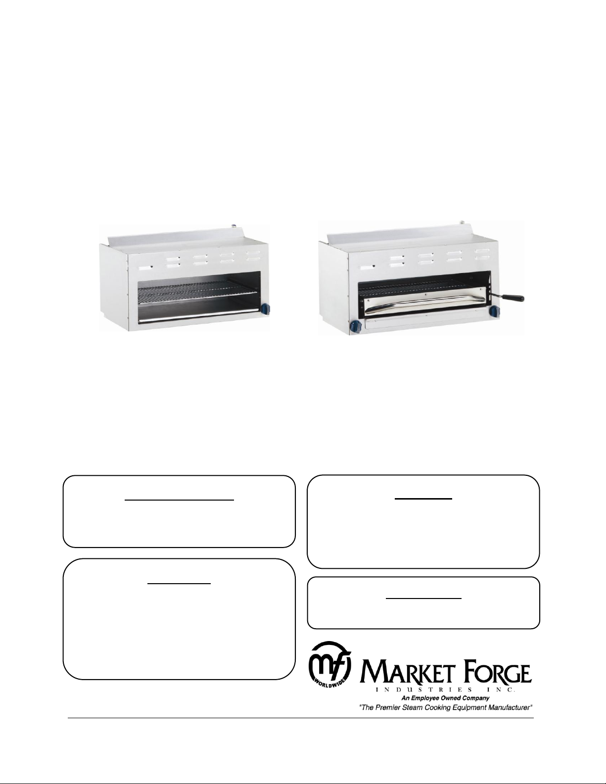
OWNER’S MANUAL
CheeseMelter/Broiler
Salamander/Broiler
MODELS:
□ R-RCM-24
□ R-RCM-36
□ R-RCM-48
□ R-RCM-60
MODELS:
□ R-RSB-24
□ R-RSB-36
□ R-RSB-48
WARNING:
IMPROPER INSTALLATION, ADJUSTMENT,
ALTERATION, SERVICE OR MAINTENANCE CAN
CAUSE PROPERTY DAMAGE, INJURY OR DEATH.
READ THESE INSTALLATION, OPERATION AND
MAINTENANCE INSTRUCTIONS THOROUGHLY
BEFORE INSTALLING OR SERVICING THIS
EQUIPMENT.
FOR YOUR SAFETY:
DO NOT STORE OR USE GASOLINE OR OTHER
FLAMMABLE VAPORS OR LIQUIDS IN THE VICINITY
OF THIS OR ANY OTHER APPLIANCE.
Form Number: S-6103 10/12
Printed in USA 35 Garvey Street, Everett, MA 02149
Telephone (617) 387-4100, (866) 698-3188, Fax (617) 387-4456, (800) 227-2659
custserv@mfii.com, www.mfii.com
CAUTION:
INSTRICTIONS TO BE FOLLOWED IN THE EVENT
THE USER SMELLS GAS SHALL BE POSTED IN A
PROMINENT LOCATION. THIS INFORMATION
SHALL BE OBTAINED BY CONSULTING THE LOCAL
GAS SUPPLIER.
IMPORTANT:
MUST ORDER REINFORCEMENT CHANNELS IF
MOUNTING TO OVEN OR RANGE.
INSTALLATION, OPERATION, MAINTENANCE, SERIVE & PARTS LIST

1
Table of Contents
INTRODUCTION .............................................................................................................................. 2
Important Information: ............................................................................................................... 2
Shipping Damage Claim Procedure: ............................................................................................ 2
Visible loss or damage: ........................................................................................................... 2
File claim for damages immediately: ...................................................................................... 2
Concealed loss or damage: ..................................................................................................... 2
Service: ........................................................................................................................................ 2
Air Supply and Ventilation:.......................................................................................................... 3
Disclaimer: ................................................................................................................................... 3
INSTALLATION ................................................................................................................................ 4
READ BEFORE INSTALLING .......................................................................................................... 4
Clearance: ............................................................................................................................... 4
Rating Plate: ............................................................................................................................ 4
Gas Connection: ...................................................................................................................... 4
Manual Shut-Off Valve: ........................................................................................................... 4
Pressure Regulator: ................................................................................................................. 4
Dimensions:............................................................................................................................. 5
Connections: ........................................................................................................................... 5
Initial Pilot Lighting: ................................................................................................................ 5
Specifications: ............................................................................................................................. 6
CheeseMelter .......................................................................................................................... 6
Salamander ............................................................................................................................. 6
Standard Features: ...................................................................................................................... 6
Broiler Grid: ............................................................................................................................. 6
Rack Assembly: ....................................................................................................................... 6
Adjustable Rack: ...................................................................................................................... 6
ASSEMBLY ....................................................................................................................................... 7
RANGE MOUNTING: .................................................................................................................... 7
COUNTER or WALL MOUNTING: ................................................................................................. 7
OPERATION ..................................................................................................................................... 8
LIGHTING & SHUTDOWN: ........................................................................................................... 8
MAINTENANCE ............................................................................................................................... 9
Daily Cleaning: ......................................................................................................................... 9
Periodic Cleaning: ................................................................................................................... 9
Cleaning Stainless Steel: ......................................................................................................... 9
ILLUSTRATED PARTS ..................................................................................................................... 10
CheeseMelter Exploded View ............................................................................................... 10
CheeseMelter Parts List ........................................................................................................ 11
Salamander Exploded Views ................................................................................................. 13
Salamander Parts List ............................................................................................................ 14

2
INTRODUCTION
Installation of the equipment should be performed by qualified, certified and authorized personal who
are familiar and experienced with local installation codes.
Before installation please red instructions completely and carefully.
Do not remove permanently affixed labels, warnings or plates from unit.
Important Information:
Please observe all local and national codes and ordinances. Installation must conform with local codes,
or in the absence of local codes, the National Fuel Gas Code ANSI Z223.1. In Canada, installation must
conform to installation codes for gas burning appliances and equipment standard CAN/CGA-B149.1 or
the Propane installation code CAN/CGA-B149.2 as applicable.
A manual gas shut off valve must be installed in the gas supply line ahead of the unit and gas pressure
regulator for safety and ease in servicing.
The gas pressure regulator supplied must be installed on the unit prior to connecting the equipment to
the gas line. Failure to install a regulator could be potentially hazardous and will void warranty.
The unit and its individual shut off valve must be disconnected from the gas supply piping system during
any pressure testing for that system at test pressures in excess of 1/2 PSI.
The unit must be isolated from gas supply piping system, by closing its individual manual shut off valve
during and pressure testing of the gas supply piping system at test pressure equal to or less than 1/2 PSI.
Shipping Damage Claim Procedure:
The equipment is crafted and inspected carefully by skilled personnel before leaving the factory. The
transportation company assumes full responsibility for safe delivery upon acceptance of this equipment.
If shipment arrives damaged:
Visible loss or damage:
Note the damage or loss on freight bill or express delivery and signed by the person making the delivery.
File claim for damages immediately:
Regardless of the extent of damages.
Concealed loss or damage:
If damage is noticed after unpacking, notify the transportation company immediately and file a
"Concealed Damage" claim with them. This should be done within fifteen (15) days from the date
delivered. Retain container for inspection.
Service:
Installation & Service of the equipment should be performed by qualified, certified, licensed and/or
authorized personnel who are familiar with and experienced in state/local installation codes.
Operation of the equipment should be performed by qualified and authorized personnel who have read
this manual and are familiar with the functions of the equipment.

3
Air Supply and Ventilation:
The area in front of, around and above the appliance must be kept clear to avoid any obstruction of the
flow of combustion and ventilation air. Adequate clearance must be maintained at all times in front and
at the sides of the appliances for servicing and proper operation.
Means must be provided for any commercial, heavy-duty cooking appliance to exhaust combustion
waste products to the outside of the building. Usual practice is to place the unit under an exhaust hood.
Filters and drip troughs should be part of any industrial hood. Consult local codes before constructing
and installing a hood.
Strong exhaust fans in this hood or in the overall air conditioning system can produce a slight vacuum in
the room and/or cause air drafts, either of which can interfere with pilot or burner performance and can
also be hard to diagnose. Air movement should be checked during installation; if pilot or burner outage
problems persist, make-up air openings or baffles may have to be provided in the room.
Disclaimer:
All MARKET FORGE INDUSTRIES, INC. appliances are adjusted and tested before leaving the factory,
effectively matching them to sea level conditions. Adjustments and calibrations to assure proper
operation may be necessary on installation to meet local conditions; low gas characteristics, to correct
possible problems caused by rough handling or vibration during shipment, and are to be performed only
by qualified service personnel. These adjustments are the responsibility of the customer and/or dealer
and are not covered by our warranty.

4
INSTALLATION
UNIT MUST BE CONNECTED ONLY TO THE TYPE OF GAS IDENTIFIED ON THE RATING PLATE!
READ BEFORE INSTALLING
Clearance:
When installing against combustible surfaces; rear and sides - 4” (102mm) clearance is required. When
installing ovens against non-combustible surfaces (rear or side walls) 0” clearance is required.
The area around the appliance must be kept free and clear of combustibles such as solvents, cleaning
liquid, broom, rags, etc. Proper clearances must be provided at the front of the appliance for servicing
and proper operation.
Rating Plate:
The rating plate is located in front of the range below the oven section. Information on this plate
includes the model, and serial number, BTU / hour input of the burners, operating gas pressure in inches
WC, and whether the appliance is orificed for Natural or Propane gas. Pilot lighting instructions are also
located in the same area.
Gas Connection:
The gas supply (service) line must be the same size or greater than the inlet line of appliance. Oven uses
a 3/4” NPT inlet. Sealant on all pipe joints must be resistive to LP gas. Specify type of gas and altitude if
over 2,000 feet when ordering.
Manual Shut-Off Valve:
This installer-supplied valve must be installed in the gas service line ahead of the appliance and
regulator in the gas stream and in a position accessible in the event of an emergency.
Pressure Regulator:
Gas pressure regulator provided with the equipment must be installed when the appliance is connected
to gas supply.
All commercial cooking equipment must have a pressure regulator on the incoming service line for safe
and efficient operation, since service pressure may fluctuate with local demand. The pressure regulator
comes with the oven. Failure to install the pressure regulator will void the equipment warranty!
The regulators supplied with MARKET FORGE INDUSTRIES, INC. Ovens, have 3/4” inlet /outlet openings
and are adjusted at the factory for 5” WC (Natural gas) or 10” WC (Propane gas) depending on
customer’s ordering instructions.
Prior to connecting the regulator, check the incoming line pressure, as these regulators can only
withstand a maximum pressure of ½ PSI (14”WC). If the line pressure is beyond this limit, a step-down
regulator will be required. The arrow shown on the bottom of the regulator body shows gas flow
direction; it should point downstream to the appliance. The red air vent cap on the top regulator is part
of the regulator and should not be removed.

5
Any adjustments to regulators must be made only by qualified service personnel with the proper
Before lighting, check all joints in the gas supply line for leaks.
DO NOT USE AN OPEN FLAME TO CHECK FOR LEAKS!
Putting an open flame beside a new gas connection is extremely dangerous.
DO NOT USE APPLIANCE DURING PROLONGED POWER FAILURE AS THE VENT HOOD MAY NOT BE IN
OPERATION RESULTING IN INADEQUATE VENTING!
CAUTION: When lighting pilots and checking for leaks, do not stand with your face close to the
combustion chamber.
Check all gas connections for leaks with a soapy water solution before lighting any pilots.
equipment.
Dimensions:
Connections:
Please check installer-supplied intake pipes visually and /or blow them out with compressed air to clear
any dirt particles, threading chips, or other foreign matter before installing a service line. When gas
pressure is applied these particles can clog orifices. All connections must be sealed with a joint
compound suitable for LP gas, and all connections must be tested with a soapy water solution before
lighting any pilots!
Initial Pilot Lighting:

6
Specifications:
MODEL
WIDTH
NO. OF BURNERS
TOTAL BTU
SHIP WEIGHT
R-RCM-24
24” (610mm)
11
20,000
105 lbs.
R-RCM-36
36” (914mm)
12
35,000
165 lbs.
R-RCM-48
48” (1219mm)
21
40,000
210 lbs.
R-RCM-60
60” (1524mm)
2
1&2
55,000
275 lbs.
MODEL
WIDTH
NO. OF BURNERS
TOTAL BTU
SHIP WEIGHT
R-RSB-24
24” (610mm)
11
17,500
160 lbs.
R-RSB-36
36” (914mm)
21
35,000
201 lbs.
R-RSB-48
48” (1219mm)
22
40,000
252 lbs.
CheeseMelter
Salamander
1
Infra-red burner rated at 20,000 BTU/hr each.
2
Infra-red burner rated at 35,000 BTU/hr each.
Standard Features:
Standard features for both units include, high efficient infra-red burners provide uniform heating,
removable crumb tray, adjustable infra-red burners, standing pilots for instant ignition and wall
mounting brackets.
The CheeseMelter/Broiler also comes with heavy duty chrome racks, that easily move in two positions,
and a full drip pan for easy clean up.
The Salamander/Broiler is equipped with spring balanced broiler grid that moves up and down with
positive locking in three positions, and roll-out carriage for easy loading and unloading.
Broiler Grid:
One piece broiler grid chrome plated and made of heavy duty bar stock.
Rack Assembly:
Rolls out adequately for loading, unloading and removes for cleaning.
Adjustable Rack:
Only available on salamander models. Broiler rack has spring balance and adjustable tension assembly
(rises and lowers with positive multi-position locking).

7
ASSEMBLY
RANGE MOUNTING:
Available to mount on any Market Forge Range using optional heavy duty reinforcement channels (p/n
00-0000) that fit existing back guard.
COUNTER or WALL MOUNTING:
Mount on any counter surface with the optional 4” legs. Also, mount on any wall type with the optional
wall mounting kit (p/n 00-0000).
NOTE: If a Salamander /Broiler or CheeseMelter/Broiler is to be mounted on range, it should be
installed by an authorized service tech. Special care must be taken to ensure that the gas supply piping
and/or gas pressure regulator is not exposed to exhaust gases, or elevated temperatures.
NOTE: Width of the unit cannot exceed width of the range it is mounted on.

8
OPERATION
Before lighting any pilots, make sure that burner valves and thermostats are turned “off”.
LIGHTING & SHUTDOWN:
1. Turn all valves to OFF position.
2. Wait 5 minutes.
3. Turn pilot valve(s) adjusting screw counterclockwise, then light standing pilot and adjust
flame 1/4” high.
4. Turn ON gas valve(s) to light main burner.
5. For complete shutdown, shut OFF gas valve(s) and turn pilot valve(s) adjusting screws
clockwise

9
MAINTENANCE
If the appliance is on casters and is connected to the supply piping by means of a connector for movable
appliances, there is a restraining device at the rear of the unit. If disconnection of the restraint is
necessary, reconnect the restraint after the appliance has been returned to its originally installed
position.
CAUTION: Never use Ammonia in an Oven that is warmer than room temperature and always have
direct ventilation.
Daily Cleaning:
1. Remove large pieces of food residues and carefully scrape spill lovers from drip tray below the
cooking surface.
2. Wash all exterior and interior surfaces with hot soapy water solution. Do not use any abrasives
on any other portion of the stainless steel surface.
3. Cast iron grates should be scraped frequently with a wire brush and periodically soaked in soapy
hot water to remove grease particles. Never expose the grates to excessive heat for the purpose
of burning excess grease. This practice could shorten the useful life of the grates.
4. Infra-red burners available on cheesmelters and Salamanders are self-cleaning. The use of any
solvents or wire brushes nay damage tiles.
5. For charbroilers use lava rock. This pumice rock is highly porous and relatively self-cleaning. The
lava rock should be turned over about every week depending upon the amount of cooking and
type of food prepared.
High heat will effectively clean and burn off grease. A loosely placed lower layer of rock will
serve as an effective base. About one half layer of rock should be added to compensate for hot
pots. Over filling the char broiler will obstruct proper air flow creating poor combustion and
uneven heating pattern and will ultimately shorten the useful life of cast iron bottom grates and
burners. As the lava rock disintegrates over a period of time it needs replacement.
Periodic Cleaning:
Remove burner and clean with warm water and wire brush. Make sure the ports are not clogged. Check
valves and lubricate, if necessary. Consult your service agency or local Gas Company.
Cleaning Stainless Steel:
All stainless steel body parts should be wiped regularly with hot soapy water during the day and with a
liquid cleaner designed for this material at the end of each day.
DO NOT USE steel wool, abrasive cloths, cleaners or powders to clean stainless surfaces! If it is
necessary to scrape stainless steel to remove encrusted materials, soak in hot water to loosen the
material; then use a wood or nylon scraper.
DO NOT USE a metal knife, spatula, or any other metal tool to scrape stainless steel. Scratches are
almost impossible to remove.

10
CheeseMelter Exploded View
ILLUSTRATED PARTS

11
CheeseMelter Parts List
ITEM
NO.
PART
NO.
DESCRIPTION
1
93-5343
24" Top cover
93-5344
36" Top cover
93-5345
48" Top cover
93-5346
60" Top cover
93-5347
72" Top cover
2
93-5348
Infra-red burner – Small B-20 (RCM-24”, 48”, 60”)
93-5349
Infra-red burner – Big B-35 (RCM-36”, 60”, 72”)
3
93-5350
Pilot burner w/bell orifice (natural gas)
93-5351
Pilot burner w/bell orifice (propane gas)
93-5352
#18 Pilot bell orifice only (natural gas)
93-5353
#10 Pilot bell orifice only (propane gas)
4
93-5354
Gas pressure regulator (natural gas)
93-5355
Gas pressure regulator (propane Gas)
5
93-5356
Orifice spud #46 (brass) natural gas, 20,000BTU*
93-53
57
Orifice hood #46 (alternate) natural gas 20,000BTU*
93-5358
Orifice spud #55 (brass) natural gas, 20,000BTU*
93-53
59
Orifice hood #55 (alternate) propane, 20,000BTU*
93-5360
Orifice spud #39 (brass) natural gas, 30,000BTU*
93-5361
Orifice hood # 39 (alternate) natural gas, 30,000BTU*
93-5362
Orifice spud #52 (brass) propane, 30,000BTU*
93-5363
Orifice hood #52 (alternate) propane, 30,000BTU*
93-5364
90º Orifice elbow, rectangular (brass)
6
93-5365
3/8” CC x 3/8-27 Orifice elbow (brass)
7
93-5366
Manifold pipe assembly (right side gas inlet)
93-5367
Manifold pipe assembly (left side complimentary assy)
8
93-5368
1/8" NPT x 3/16" CC Adjustable single pilot valve (brass)
9
93-5369
3/8-27 x 3/8" CC Adapter
10
93-5370
Gas valve (brass) w/out orifice
11
93-5371
Blue knob – flat side down
12
93-5372
24” Crumb tray
93-5373
36” Crumb tray
93-5374
48” Crumb tray
93-5375
60” Crumb tray
93-5376
72” Crumb tray
13
93-5377
24" Chrome rack
93-5378
36" Chrome rack
93-5379
48" Chrome rack
93-5380
60" Chrome rack
93-5381
72" Chrome rack
14
93-5382
24” Wall mount kit
93-5383
36” Wall mount kit
93-5384
48” Wall mount kit
93-5385
60” Wall mount kit

12
ITEM
NO.
PART
NO.
DESCRIPTION
14
93-5386
72” Wall mount kit
15
93-5387
Reinforcement Channels (range mount kit, specify range model# )
* Verify which construction is applicable for your burner type.

13
Salamander Exploded Views

14
Salamander Parts List
ITEM
NO.
PART
NO.
DESCRIPTION
1
93-5388
24” Top cover
93-5389
36” Top cover
93-5390
48” Top cover
2
93-5391
Infra-red burner - Small B-15(RSB-36 – 2 burner)
93-5392
Infra-red burner – Big B-20 (RSB-24 – 1 burner)
93-5393
Pilot burner with bell orifice (natural gas)
3
93-5394
Pilot burner with bell orifice (propane Gas)
93-5395
#18 Pilot bell orifice only (natural gas)
93-5396
#10 Pilot bell orifice only (propane Gas)
4
93-5397
Gas pressure regulator (natural gas)
93-5398
Gas pressure regulator (propane Gas)
5
93-5399
Orifice spud #46 (brass), natural gas (for 24”), 20,000BTU*
93-5400
Orifice hood #46 (alternate), natural gas (for 24”), 20,000BTU*
93-5401
Orifice spud #55 (brass), propane (for 24”), 20,000BTU*
93-5402
Orifice hood #55 (alternate), propane (for 24”), 20,000BTU*
93-5403
Orifice spud #48 (brass), natural gas (for 36“), 18,000BTU
93-5404
Orifice hood #48 (alternate) natural gas (for 36”) 18,000BTU
93-5405
Orifice spud # 56 (brass), propane (for 36”) 18,000BTU
93-5406
Orifice hood #56 (alternate), propane(for 36“), 18,000BTU
6
93-5407
3/8” CC x 3/8-27 Orifice elbow (brass)
93-5408
90o Orifice elbow (rectangular) (brass)
7
93-5409
Manifold pipe assembly (right side gas inlet)
93-5410
Manifold pipe assembly (left side assembly)
8
93-5411
1/8" NPT x 3/16" CC Adjustable single pilot valve (brass)
9
93-5412
3/8-27 x 3/8" CC Adapter (gas valve)
10
93-5413
Gas valve (brass) w/out orifice
11
93-5414
Blue knob – flat side down
93-5415
24" Cradle frame assembly
12
93-5416
36" Cradle frame assembly
93-5417
48” Cradle frame assembly
13
93-5418
Latch bracket
14
93-5419
24” Crumb tray assy.
93-5420
36” Crumb tray assy.
93-5421
48” Crumb tray assy.
15
93-5422
24" Rack assembly with pull out handle
93-5423
36" Rack assembly with pull out handle
93-5424
48” Rack assembly with pull out handle
93-5425
24” Drip pan
16
93-5426
36” Drip pan
93-5427
48” Drip pan
93-5428
24” Chrome rack

15
ITEM
NO.
PART
NO.
DESCRIPTION
17
93-5429
36” Chrome rack
93-5430
48” Chrome rack
93-5431
24” Front panel
18
93-5432
36” Front panel
93-5433
48” Front panel
93-5434
24” Wall mount kit
19
93-5435
36” Wall mount kit
93-5436
48” Wall mount kit
20
93-5437
Reinforcement Channels (range mount kit, specify range model# )
* Verify which construction is applicable for your burner type.
 Loading...