

Page 1
0
OWNER’S MANUAL
WARNING:
IMPROPER INSTALLATION, ADJUSTMENT,
ALTERATION, SERVICE OR MAINTENANCE CAN
CAUSE PROPERTY DAMAGE, INJURY OR DEATH.
READ THESE INSTALLATION, OPERATION AND
MAINTENANCE INSTRUCTIONS THOROUGHLY
BEFORE INSTALLING OR SERVICING THIS
EQUIPMENT.
FOR YOUR SAFETY:
DO NOT STORE OR USE GASOLINE OR OTHER
FLAMMABLE VAPORS OR LIQUIDS IN THE VICINITY
OF THIS OR ANY OTHER APPLIANCE.
Form Number: S-6102 1/13
Printed in USA 35 Garvey Street, Everett, MA 02149
Telephone (617) 387-4100, (866) 698-3188, Fax (617) 387-4456, (800) 227-2659
custserv@mfii.com, www.mfii.com
CAUTION:
INSTRICTIONS TO BE FOLLOWED IN THE EVENT
THE USER SMELLS GAS SHALL BE POSTED IN A
PROMINENT LOCATION. THIS INFORMATION
SHALL BE OBTAINED BY CONSULTING THE LOCAL
GAS SUPPLIER.
Heavy Duty Gas Ranges
Standard & Raised Griddles
24” Models: □ R-R4 □ R-R2G-12 □ R-RG24
36” Models: □ R-R6 □ R-R4G-12 □ R-R2G24 □ R-RG36 □ R-R4RG12
48” Models: □ R-R8 □ R-RG12-6 □ R-RG24-4 □ R-RG36-2 □ R-RG48 □ R-RRG24-4
60” Models: □ R-R10 □ R-RG12-8 □ R-RG24-6 □ R-RG36-4 □ R-RG48-2 □ R-RG60
□ R-RRG24-6
Page 2

1
INTRODUCTION ............................................................................................................................................ 2
TABLE OF CONTENTS
Important Information: ............................................................................................................................. 2
Shipping Damage Claim Procedure: .......................................................................................................... 2
Visible loss or damage: ......................................................................................................................... 2
File claim for damages immediately: ................................................................................................... 2
Concealed loss or damage: .................................................................................................................. 2
Service: ...................................................................................................................................................... 2
Air Supply and Ventilation: ....................................................................................................................... 3
INSTALLATION .............................................................................................................................................. 4
READ BEFORE INSTALLING ........................................................................................................................ 4
Clearance: ............................................................................................................................................. 4
Leveling: ............................................................................................................................................... 4
Rating Plate: ......................................................................................................................................... 4
Electrical Connection: ........................................................................................................................... 4
Gas Connection: ................................................................................................................................... 4
Dimensions and Burner Options: ......................................................................................................... 5
Manual Shut-Off Valve: ........................................................................................................................ 6
Pressure Regulator: .............................................................................................................................. 6
Connections: ......................................................................................................................................... 6
Flexible Coupling, Connectors and Casters: ......................................................................................... 6
Check for Gas Leaks: ................................................................................................................................. 7
Disclaimer: ................................................................................................................................................ 7
Wiring Diagram - Range Convection Oven:............................................................................................... 8
ASSEMBLY ..................................................................................................................................................... 9
HIGH SHELF ASSEMBLY: ............................................................................................................................ 9
OPERATION ................................................................................................................................................. 10
BEFORE FIRST USE ................................................................................................................................... 10
Griddles: ............................................................................................................................................. 10
Ovens: ................................................................................................................................................. 10
TOP BURNERS / RAISED GRIDDLE–BROILER / BROILER .......................................................................... 10
HOT TOP / GRIDDLE ................................................................................................................................ 10
STANDARD OVEN .................................................................................................................................... 10
MAINTENANCE ........................................................................................................................................... 12
Daily Cleaning: .................................................................................................................................... 12
All Ovens and Salamander/Broiler: .................................................................................................... 12
Periodic Cleaning: ............................................................................................................................... 12
Cleaning Stainless Steel: ..................................................................................................................... 12
ILLUSTRATED PARTS ................................................................................................................................... 13
Complete Range Exploded View ........................................................................................................ 13
Complete Range Parts List .................................................................................................................. 14
Griddle, Radiant Broiler and Raised Griddle Exploded Views ............................................................ 17
Griddle, Radiant Broiler and Raised Griddle Parts List ....................................................................... 18
Convection Oven Exploded View ....................................................................................................... 20
Convection Oven Parts List ................................................................................................................. 21
Page 3

2
INTRODUCTION
Important Information:
Safe and satisfactory operation of your equipment depends on proper installation. Installation must
conform with local codes, or in the absence of local codes, the National Fuel Gas Code, (ANSI Z-223.1
Latest Edition). In Canada installation should conform to installation codes for gas burning appliances
and equipment standard (CAN1-B149.1 Natural Gas) or (CAN1-B149.2 Propane Gas).
The installation must conform with local codes, or in the absence of local codes, to the national fuel gas
code, ANSI Z223.1 (or latest addenda). The Appliance and its individual shut off valve must be
disconnected from the gas supply piping system during any pressure testing of that system in excess of
1/2 PSI (3.45Kpa).
The appliance must be isolated from the gas supply piping system by closing its individual manual shut
off valve during any pressure testing of the gas supply piping system at test pressures equal to or less
than 1/2 PSI (3.45Kpa). The gas supply line must be at least the same size as the gas inlet of the
appliance.
Electrical wiring from the Electric Meter, main control box or service outlet to appliance must be
electrically grounded in accordance with local codes or, in the absence of local codes, the National
Electric Code (ANSI/NFPA 70 Current). In Canada wiring should conform with Canadian Electrical Code
(CSA-C22.1).
Shipping Damage Claim Procedure:
The equipment is crafted and inspected carefully by skilled personnel before leaving the factory. The
transportation company assumes full responsibility for safe delivery upon acceptance of this equipment.
If shipment arrives damaged:
Visible loss or damage:
Note the damage or loss on freight bill or express delivery and signed by the person making the delivery.
File claim for damages immediately:
Regardless of the extent of damages.
Concealed loss or damage:
If damage is noticed after unpacking, notify the transportation company immediately and file a
"Concealed Damage" claim with them. This should be done within fifteen (15) days from the date
delivered. Retain container for inspection.
Service:
Installation of the equipment should be performed by qualified, certified, licensed and/or authorized
personnel who are familiar with and experienced in state/local installation codes.
Operation of the equipment should be performed by qualified and authorized personnel who have read
this manual and are familiar with the functions of the equipment.
Service of the equipment should be performed by qualified personnel who are knowledgeable with
Market Forge cooking equipment.
Page 4

3
Air Supply and Ventilation:
Provisions shall be incorporated in the design of the kitchen, to ensure adequate supply of fresh air and
adequate clearance for air openings into the combustion chamber, for proper combustion, and
ventilation. For proper operation of the appliance, do not obstruct the flow of combustion and
ventilation air.
The area in front of, around and above the appliance must be kept clear to avoid any obstruction of the
flow of combustion and ventilation air. Adequate clearance must be maintained at all times in front and
at the sides of the appliances for servicing and proper operation.
Means must be provided for any commercial, heavy-duty cooking appliance to exhaust combustion
waste products to the outside of the building. Usual practice is to place the unit under an exhaust hood.
Filters and drip troughs should be part of any industrial hood. Consult local codes before constructing
and installing a hood.
Strong exhaust fans in this hood or in the overall air conditioning system can produce a slight vacuum in
the room and/or cause air drafts, either of which can interfere with pilot or burner performance and can
also be hard to diagnose. Air movement should be checked during installation; if pilot or burner outage
problems persist, make-up air openings or baffles may have to be provided in the room.
Page 5

4
INSTALLATION
UNIT MUST BE CONNECTED ONLY TO THE TYPE OF GAS IDENTIFIED ON THE RATING PLATE!
READ BEFORE INSTALLING
Clearance:
When installing against combustible surfaces; rear - 4” (102mm) and sides - 15” (381mm) clearance is
required. When installing ovens against non-combustible surfaces (rear or side walls) 0” clearance is
required.
The area around the appliance must be kept free and clear of combustibles such as solvents, cleaning
liquid, broom, rags, etc. Proper clearances must be provided at the front of the appliance for servicing
and proper operation.
Leveling:
A carpenter’s spirit level should be placed on the oven’s center baking rack and the unit leveled both
front-to-back and side-to-side. If it is not level, cakes, casseroles, and any other liquid or semi-liquid
batter will not bake evenly, burner combustion may be erratic, and the unit will not function efficiently.
If the floor is relatively smooth and level, the unit may be further leveled with adjustment in the foot of
the leg. Units with casters must be leveled with shims. A unit will probably not return to the same
position after being moved, requiring re-leveling after each and every move.
Rating Plate:
The rating plate is located in front of the range below the oven section. Information on this plate
includes the model, and serial number, BTU / hour input of the burners, operating gas pressure in inches
WC, and whether the appliance is orificed for Natural or Propane gas. Pilot lighting instructions are also
located in the same area.
Electrical Connection:
Oven requires a 120 volt supply to operate the ignition system and blower. The supply cord provided
along with the appliance is equipped with a three prong (grounding) plug for protection against shock
hazard. The electrical service in the building must be equipped with a properly grounded three prong
receptacle, in accordance with local codes, or in the absence of local codes, with the national electrical
code, ANSI/NFPA 70-1987, in Canada, conform with Canadian electrical codes, CSA-C22.1.
Do not cut or remove the grounding prong from this plug. Wiring diagram is located on the backside of
the appliance.
Disconnect power supply before cleaning or servicing.
NOTE: This appliance is not capable of being operated in the event of power failure. No attempt should
be made to operate this appliance during power failure.
Gas Connection:
The gas supply (service) line must be the same size or greater than the inlet line of appliance. Oven uses
a 3/4” NPT inlet. Sealant on all pipe joints must be resistive to LP gas.
Page 6
5
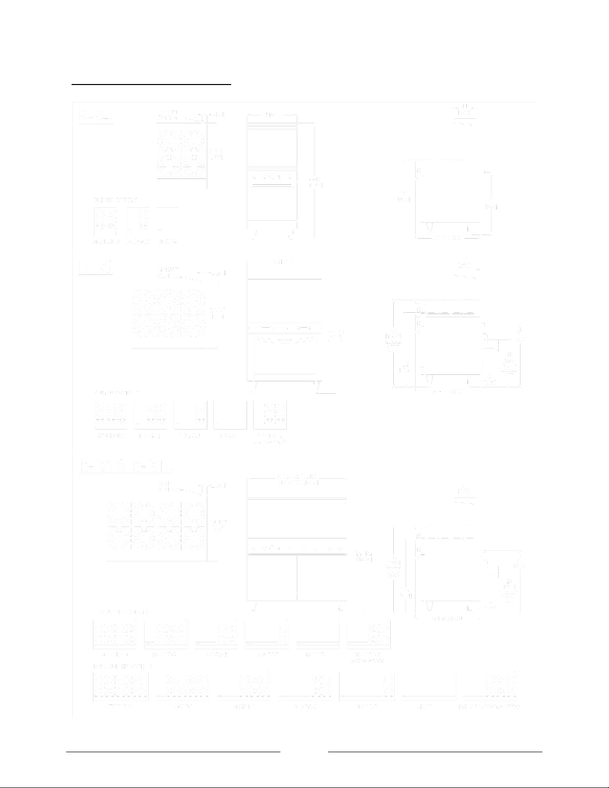
Dimensions and Burner Options:
Page 7

6
Manual Shut-Off Valve:
Before lighting, check all joints in the gas supply line for leaks.
DO NOT USE AN OPEN FLAME TO CHECK FOR LEAKS!
Putting an open flame beside a new gas connection is extremely dangerous.
This installer-supplied valve must be installed in the gas service line ahead of the appliance and
regulator in the gas stream and in a position accessible in the event of an emergency.
Pressure Regulator:
Gas pressure regulator provided with the equipment must be installed when the appliance is connected
to gas supply.
All commercial cooking equipment must have a pressure regulator on the incoming service line for safe
and efficient operation, since service pressure may fluctuate with local demand. The pressure regulator
comes with the oven. Failure to install the pressure regulator will void the equipment warranty!
The regulators supplied with MARKET FORGE INDUSTRIES, INC. Ovens, have 3/4” inlet /outlet openings
and are adjusted at the factory for 5” WC (Natural gas) or 10” WC (Propane gas) depending on
customer’s ordering instructions.
Prior to connecting the regulator, check the incoming line pressure, as these regulators can only
withstand a maximum pressure of ½ PSI (14”WC). If the line pressure is beyond this limit, a step-down
regulator will be required. The arrow shown on the bottom of the regulator body shows gas flow
direction; it should point downstream to the appliance. The red air vent cap on the top regulator is part
of the regulator and should not be removed.
Any adjustments to regulators must be made only by qualified service personnel with the proper
equipment.
Connections:
Please check installer-supplied intake pipes visually and /or blow them out with compressed air to clear
any dirt particles, threading chips, or other foreign matter before installing a service line. When gas
pressure is applied these particles can clog orifices. All connections must be sealed with a joint
compound suitable for LP gas, and all connections must be tested with a soapy water solution before
lighting any pilots!
Flexible Coupling, Connectors and Casters:
For an appliance equipped with casters the installation shall be made with a connector that complies
with the Standard for Connectors for Movable Gas Appliances, ANSI Z21.69 or Connectors for Moveable
Gas Appliances, CAN/CGA-6.16, and a quick –disconnect device that complies with the standard for
Quick Disconnect Devices for Use with Gas Fuel, ANSI Z21.41, or Quick Disconnect Devices for Use with
Gas Fuel, CANI-6.9. Adequate means must be provided to limit the movement of the appliance without
depending on the connector and the quick-disconnect device or its associated piping to limit the
appliance movement. Restraining devices may be attached to the back frame/panel of the unit.
If legs or casters are not used, the unit must extend 2” beyond the front edge of a noncombustible curb
or platform. Broilers are for installation in non-combustible locations only.
Page 8

7
DO NOT USE APPLIANCE DURING PROLONGED POWER FAILURE AS THE VENT HOOD MAY NOT BE IN
OPERATION RESULTING IN INADEQUATE VENTING!
INITIAL PILOT LIGHTING:
CAUTION: When lighting pilots and checking for leaks, do not stand with your face close to the
combustion chamber.
Check for Gas Leaks:
1. Remove the kick plate and the component cover at the rear of the oven
2. Check pilot tubing and burner tubing for leaks at the connectors with a soapy water solution.
3. Light the pilot as described above.
4. Turn the thermostat to any setting and the burner should light.
5. Check the burner orifice elbow connection downstream of the valve with a soapy water
solution.
6. Check the burner visually for blue flame. There should be no yellow tips or soot. If yellow tipping
occurs, call an authorized service person to adjust the burner air shutter.
Disclaimer:
All MARKET FORGE INDUSTRIES, INC. appliances are adjusted and tested before leaving the factory,
effectively matching them to sea level conditions. Adjustments and calibrations to assure proper
operation may be necessary on installation to meet local conditions; low gas characteristics, to correct
possible problems caused by rough handling or vibration during shipment, and are to be performed only
by qualified service personnel. These adjustments are the responsibility of the customer and/or dealer
and are not covered by our warranty.
Page 9

8
Wiring Diagram - Range Convection Oven:
Page 10

9
ASSEMBLY
HIGH SHELF ASSEMBLY:
1. Mount the back guard/ flue riser to the range with #10 sheet metal screws (12 total) in the back.
2. Mount the high shelf to the riser with 1/4-20 x 1/2 bolts provided (refer to the illustrated parts
list in the back of this manual for the parts assembly of the back guard / flue riser).
NOTE: An authorized Service Personnel should install these items. If a Salamander /Broiler or
CheeseMelter/Broiler is to be mounted on range, read installation instructions for Salamander
/Broiler or CheeseMelter/Broiler (form no. S-6103) before installing high shelf. Special care must be
taken to ensure that the gas supply piping and/or gas pressure regulator is not exposed to exhaust
gases, or elevated temperatures.
Page 11

10
OPERATION
Before lighting any pilots, make sure that burner valves and thermostats are turned “off”.
BEFORE FIRST USE
Griddles:
1. Clean the griddle surface thoroughly with hot, soapy water remove to protective oil coating
applied at the factory.
2. Rinse with a mixture of ~ cup vinegar to one quart water.
3. Spread unsalted solid shortening or liquid frying compound evenly over the entire griddle
surface.
4. Turn all griddle burners to medium and wait until the shortening begins to smoke, then turn the
burners 'off '.
5. Rub the now melted shortening into the griddle surface with burlap, moving in the direction of
the surface's polish marks and covering the entire surface.
6. Allow the griddle to cool.
7. When the griddle is cool after the second seasoning, wipe it with a thin film of shortening or
cooking oil.
Ovens:
On initial installation turn the oven to 250
maximum and operate for another hour. This will drive off any solvents remaining in the unit. At the end
of this second hour, turn the thermostat off, open the door and allow the unit to cool. Oven should be
thoroughly washed using hot soapy water before being used.
o
and operate for hour, then reset the thermostat to its
TOP BURNERS / RAISED GRIDDLE–BROILER / BROILER
All top section burners are equipped with constant-burning pilots. These are to be manually lighted
immediately after the gas is turned on and the system is checked for leaks. Burner pilots are provided
for each burner and can be rechecked for proper adjustment. Adjustments can be made with a
screwdriver to the brass pilot valve accessible through the valve cover.
HOT TOP / GRIDDLE
The pilot should be lighted immediately after the gas is turned on and the system is checked for leaks.
The pilot can be reached with a long match through the valve cover, or by lifting the plate upward and
accessing through the top.
STANDARD OVEN
Pilot gas is tapped from the main burner manifold pipe, routed through tubing to a pilot safety valve,
and then to the pilot burner. Gas flow is controlled by the safety valve.
Oven pilot lighting or relighting is to be completed in the following sequence:
1. Turn the oven thermostat knob to “off” and wait 5 minutes.
2. Remove the oven’s lower kick plate by lifting up and out. This exposes the pilot safety valve and
the igniter button.
Page 12

11
3. Make sure any accumulated gas has dispersed. Since propane gas is heavier than air, check near
the floor area for the odor of propane gas before attempting to light any pilot burners.
4. Depress the red button on the safety valve and hold it in throughout the lighting procedure.
5. Press the red button of the pilot igniter, and you should hear a snap and see a spark at the pilot
burner. If a spark or spark igniter is not present apply a lit match to the pilot burner head.
6. Continue to depress the safety valve button until the pilot remains lit when released.
7. If pilot is extinguished, repeat step 4 through 6 above.
8. Turn the oven thermostat knob “on” and set to desired temperature setting, watch to make
sure the oven burner ignites from the pilot and that there are no yellow flames from the burner.
9. Turn the oven thermostat to “off” and replace the lower kick plate.
NOTE: It may be necessary to relight the pilot several times until the lines are purged of any trapped
air and a constant gas flow is attained.
Page 13

12
MAINTENANCE
If the appliance is on casters and is connected to the supply piping by means of a connector for movable
appliances, there is a restraining device at the rear of the unit. If disconnection of the restraint is
necessary, reconnect the restraint after the appliance has been returned to its originally installed
position.
CAUTION: Never use Ammonia in an Oven that is warmer than room temperature and always have
direct ventilation.
Daily Cleaning:
Clean top grate(s) with warm water, mild cleaner and wire brush. Clean and brush off debris from and
around the burner area. Empty and clean grease pan. Griddle plates should be cleaned with warm water
and scrubbed with cleaning abrasive such as a griddle brick of fine grit type. Top surface can also be
‘bleached’ with vinegar, pickle juice or club soda when the plate is warm.
All Ovens and Salamander/Broiler:
1. Remove the baking racks. Wash in hot soapy water and replace after the rest of the oven is
cleaned.
2. Remove the oven bottom by lifting it out from the front then sliding forward, out of the oven.
3. Scrape off any food particles with a nylon griddle scraper. Be very careful about scratching the
porcelain finish on the oven liner panels.
4. Wash all the above with hot soapy water, then reassemble.
5. Baked on spills may be loosened and stubborn stains removed with ordinary household
ammonia and scrubbing with a nylon pad in a cold oven only.
6. Do not allow spray type oven cleaners to come into contact with the temperature probe in the
oven.
7. After cleaning the oven, rinse well with 1/4 cup of vinegar to one quart of clear water solution to
neutralize any caustic residue of the cleaning compound. Wipe dry.
8. Infra-red burners, available on Cheesemelters and Salamanders, are self-cleaning. The use of
any solvents or wire brushes may damage tiles.
Periodic Cleaning:
Remove burner and clean with warm water and wire brush. Make sure the ports are not clogged. Check
valves and lubricate, if necessary. Consult your service agency or local Gas Company.
Cleaning Stainless Steel:
All stainless steel body parts should be wiped regularly with hot soapy water during the day and with a
liquid cleaner designed for this material at the end of each day.
DO NOT USE steel wool, abrasive cloths, cleaners or powders to clean stainless surfaces! If it is
necessary to scrape stainless steel to remove encrusted materials, soak in hot water to loosen the
material; then use a wood or nylon scraper.
DO NOT USE a metal knife, spatula, or any other metal tool to scrape stainless steel. Scratches are
almost impossible to remove.
Page 14

13
Complete Range Exploded View
ILLUSTRATED PARTS
Page 15

14
Complete Range Parts List
ITEM
NO.
PART
NO.
DESCRIPTION
1
93-5080
12” x 24” Top grate (cast iron)
2
93-5081
Open burner (head only)
3
93-5082
Open burner gasket & screw set
4
93-5083
18" Rear venturi (cast iron)
5
93-5084
6" Front venturi (cast iron)
6
93-5085
Air shutter (mixer)
7
93-5086
Burner hanger (open burner)
8
93-5087
Pilot assembly w/ferrule and compression nut (single burner)
9
93-5088
24” Manifold pipe
93-5089
36” Manifold pipe
93-5090
48” Manifold pipe
93-5091
60” Manifold pipe
93-5092
72” Manifold pipe
10
93-5093
1/4” NPT x 3/8” CC Straight fitting (brass)
11
93-5094
B.J. Thermostat (oven only)
93-5095
1/4" NPT Plug (used to block outlet on thermostat)
12
93-5096
B.J. Thermostat flange
13
93-5097
1/8" NPT x 3/16"CC 90º adjustable single pilot valve (brass)
14
93-5098
Gas valve (brass) w/out orifice
15
93-5099
Orifice hood #42 Open burner natural, 26,000BTU
93-5100
Orifice hood #53 Open burner propane, 26,000BTU
16
93-5101
24” Valve cover
93-5102
36” Valve cover
93-5103
48” Valve cover
93-5104
60” Valve cover
93-5105
72” Valve cover
17
93-5106
Blue knob – flat side down
18
93-5107
Thermostat dial (black) – Oven only
19
93-5108
Thermostat bezel (chrome)
20
93-5109
24” Oven door (complete)
93-5110
36” Oven door (complete)
21
93-5111
24” Kick plate
93-5112
36” Kick plate
22
93-5113
24” Oven bottom
93-5114
36” Oven bottom
23
93-5115
24” Oven rack
93-5116
36” Oven rack
24
93-5117
Oven burner # 36 Orifice (brass) natural gas
93-5118
Oven burner # 50 Orifice (brass) propane gas
Page 16

15
ITEM
NO.
PART
NO.
DESCRIPTION
25
93-5119
Orifice elbow 1/4” NPT x 3/8-27 (brass)
26
93-5120
“U” burner (oven)
27
93-5121
Oven safety valve with inverted flare nut and ferrule
28
93-5122
Thermocouple
39
93-5123
Manual spark igniter w/red push button
30
93-5124
Oven Pilot – Natural gas
93-5125
Oven Pilot – Propane gas
31
93-5126
Caster 5” w/brake
32
93-5127
Caster 5” without brake
33
93-5128
Chrome cone legs
34
93-5129
Filler panel – right side
35
93-5130
Filler panel – left side
36
93-5131
24” Crumb tray
93-5132
36” Crumb tray
93-5133
48” Crumb tray (Please order 2 ea. of part # 30008)
37
93-5134
24” Landing Ledge
93-5135
36” Landing Ledge
93-5136
48” Landing Ledge
93-5137
60” Landing Ledge
93-5138
72” Landing Ledge
38
93-5139
Gas pressure regulator (nat. gas)
93-5140
Gas pressure regulator (propane Gas)
39
93-5141
Flue box assembly.
40
93-5142
24” Stub back assembly
93-5143
36” Stub back assembly
93-5144
48” Stub back assembly
93-5145
60” Stub back assembly
93-5146
72” Stub back assembly
41
93-5147
24” Back guard assembly
93-5148
36” Back guard assembly
93-5149
48” Back guard assembly
93-5150
60” Back guard assembly
93-5151
72” Back guard assembly
42
93-51
52
12" x 12" Top grate (cast iron)
43
93-51
53
Open burner – Lift off burner cap
44
93-51
54
6" Front venturi – Lift off burner base (cast iron)
45
93-51
55
18" Rear venturi – Lift off burner base (cast iron)
46
93-51
56
Burner hanger – Lift off burner
47
93-51
57
Pilot assy w/ferrule & compression nut (double burner)
48
93-51
58
Lift off burner # 39 Orifice natural gas (30,000 BTU.)
93-5159
Lift off burner # 52 Orifice propane gas (30,000 BTU.)
49
93-5160
24” Shelf
93-5161
36” Shelf
93-5162
48” Shelf
Page 17

16
ITEM
NO.
PART
NO.
DESCRIPTION
49
93-5163
60” Shelf
93-5164
70” Shelf
50
93-5165
Thermostat bulb clip
93-5166
Door frame assy. (20” oven)
51
93-5167
Door frame assy. (26 1/2” oven)
52
93-5168
1/8” NPT X 3/16” CC Brass Fitting
53
93-5169
Left Side Panel
93-5170
Right Side Panel
93-5171
Safety valve bracket (PN: 2174)
54
93-5172
Safety valve bracket (PN: 2174-B)
55
93-5173
3/8” Aluminized tubing (Specify length of tubing)
56
93-5174
3/16” Aluminized tubing (Specify length of tubing)
93-5175
Oven flame spreader (26 1/2” oven)
57
93-5176
Oven flame spreader (20” oven)
58
93-5177
Top grate support bracket
59
93-5178
Wok ring
60
93-5179
Pilot assy w/ferrule and compression nut (single burner)
61
93-5180
Pilot assy w/ferrule and compression nut (double burner)
Page 18

17
Griddle, Radiant Broiler and Raised Griddle Exploded Views
Page 19

18
Griddle, Radiant Broiler and Raised Griddle Parts List
ITEM
NO.
PART
NO.
DESCRIPTION
1
93-5181
12” Griddle plate assy. (Left)
93-5182
12” Griddle plate assy. (Right)
93-5183
24” Griddle plate assy. (Left)
93-5184
24” Griddle plate assy. (Right)
93-5185
36” Griddle plate assy. (Left)
93-5186
36” Griddle plate assy. (Right)
93-5187
48” Griddle plate assy. (Left)
93-5188
48” Griddle plate assy. (Right)
2
93-5189
“U” burner (range griddle only)
3
93-5190
Pilot tip and tube assembly, range griddle
4
93-5191
Straight burner (range griddle only)
5
93-5192
Grease can assy.
6
93-5193
12” Front baffle (Left)
93-5194
12” Front baffle (Right)
93-5195
24” Front baffle (Left)
93-5196
24” Front baffle (Right)
93-5197
36” Front baffle (Left)
93-5198
36” Front baffle (Right)
93-5199
48” Front baffle (Left)
93-5200
48” Front baffle (Right)
7
93-5201
Orifice hood (griddle) #46 (brass) natural, 20,000BTU
93-5202
Orifice hood (griddle) #55 (brass) propane, 20,000BTU
8
93-5203
Orifice elbow 3/8 CC x 3/8-27 (brass)
9
93-5204
Adapter 3/8-27 x 3/8" CC (gas valve)
10
93-5205
Gas valve (brass) w/out orifice
11
93-5206
Thermostat flange nipple
12
93-5207
B.J. Thermostat (griddle)
13
93-5208
1/4 NPT x 3/8 CC Straight fitting
14
93-5209
3" x 21" Top Grate (Cast Iron)
15
93-5210
Burner radiant (cast iron)
16
93-5211
Stainless steel burner w/ air shutter
17
93-5212
Orifice hood (RB) #50 (brass) natural, 15,000BTU
93-5213
Orifice hood (RB) #56 (brass) propane, 15,000BTU
18
93-5214
1/8" NPT x 3/16" CC Adjustable double pilot valve (brass)
19
93-5215
Pilot tip assembly
20
93-5216
Burner with radiant
21
93-5217
Orifice hood (RG) #50 (brass) natural, 20,000BTU
93-5218
Orifice hood (RG) #56 (brass) propane, 20,000BTU
22
93-5219
Blue knob – flat side up
23
93-5220
RRG-12” Manifold pipe
93-5221
RRG-24” Manifold pipe
Page 20

19
ITEM
NO.
PART
NO.
DESCRIPTION
24
93-5222
3/8” Orifice extension fitting (brass)
25
93-5223
RRG-12” Valve cover
93-5224
RRG-24” Valve cover
26
93-5225
RRG Grease can assy.
27
93-5226
1/8"NPT x 3/16CC 90º Adjustable single pilot valve (brass)
28
93-5227
Pilot tip and tube assembly, range raised griddle
29
93-5228
RRG-12” Griddle plate assy.
93-5229
RRG-24” Griddle plate assy.
30
93-5230
RRG-12” Rack
93-5231
RRG-24” Rack
31
93-5232
RRG-12” Crumb tray
93-5233
RRG-24” Crumb tray
32
93-5234
RRG-12” Drip pan
93-5235
RRG-24” Drip pan
Page 21

20
Convection Oven Exploded View
Page 22

21
Convection Oven Parts List
ITEM
NO.
PART
NO.
DESCRIPTION
1
93-5236
Indicator Light
2
93-5237
Thermostat Dial
3
93-5238
Switch, Oven Fan High/Low
4
93-5239
Switch, Power—3 Position
5
93-5240
Timer
93-5241
Knob For Timer
6
93-5242
Control Panel Decal
7
93-5243
Control Panel R/H For 36” Range
8
93-5244
Thermostat
9
93-5245
Oven Rack Guide
10
93-5246
Oven Rack
11
93-5247
Solenoid Valve
12
93-5248
Brass Fitting - 1/4 CC X 1/8 NPT X 90 Degrees
13
93-5249
Module Cover
14
93-5250
Blower Spacer Tube
15
93-5251
Blower Wheel RR-C
16
93-5252
Motor Mount Bracket
17
93-5253
Motor
18
93-5254
Motor Mount Weld Plate Assy.
19
93-5255
Snorkel Tube Weld Assembly
20
93-5256
Manifold Tubing (Manifold To Solenoid 3/8 Aluminized Tubing)
21
93-5257
Straight Connector (3/8 CC X 1/8 NPT) (Male Thread)
22
93-5258
Hex Head Bolt (1/4-20 X 4)
23
93-5259
Blower Baffle
24
93-5260
Power Cord
25
93-5261
Straight Connector (3/8 CC X 3/8 NPT) (Male Thread)
26
93-5262
RAM-4 Spark Module
27
93-5263
Oven Pilot (Natural)
93-5264
Oven Pilot (Propane)
28
93-5265
Pilot Bracket
29
93-5266
Oven Front Baffle
30
93-5267
Door Seals (Top—Bottom)
31
93-5268
Convection Base Oven Door (Complete Assy.)
32
93-5269
Convection Base Door Frame Assy.
33
93-5270
36” Kick Plate
34
93-5271
Door Seal Sides
35
93-5272
Orifice Elbow (3/8 CC X 3/8-27)
36
93-5273
Orifice Hood #39 (Brass) Natural Gas 30,000 B.T.U.
93-5274
Orifice Hood #52 (Brass) Propane Gas 30,000 B.T.U.
Page 23

22
ITEM
NO.
PART
NO.
DESCRIPTION
37
93-5275
Switch, Oven Door
38
93-52
76
Burner Tubing 3/8 Diameter Aluminum
39
93-52
77
Door Switch Bracket
40
93-52
78
Oven Elbow Bracket
41
93-52
79
“U” Burner (Oven)
42
93-52
80
Solenoid End Bracket
43
93-52
81
Solenoid Bracket
44
93-52
82
Door Switch Bracket L/H for RR-60-C
 Loading...