

Page 1
OWNER’S MANUAL
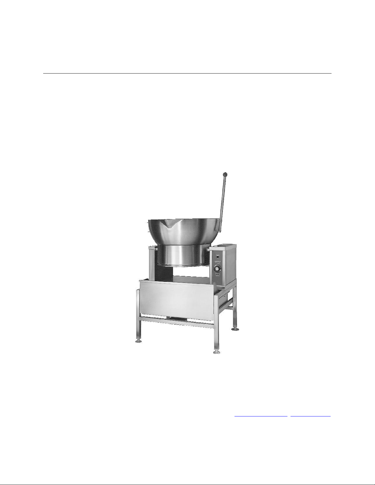
ROUND GAS COUNTER TILTING SKILLET
MODEL: □ R-1600G
Market Forge Industries Inc.
35 Garvey Street, Everett, MA 02149-4403
Telephone: (617) 387-4100, Toll Free: (866) 698-3188
Fax: (617) 387-4456, Outside MA Fax: (800) 227-2659
custserv@mfii.com, www.mfii.com
12/12 REV. B Form Number S-6001
1
Page 2

Table of Contents
Important Notes for Installation and Operating .......................................................................................... 3
Installation Instructions ............................................................................................................................ 4-5
Service Connections ...................................................................................................................................... 4
Installation Instructions ............................................................................................................................... 5
Operating Instructions .................................................................................................................................. 6
To Tilt Skillet .................................................................................................................................................. 6
Maintenance ................................................................................................................................................ 7
Periodic Maintenance .................................................................................................................................. 7
Cleaning ........................................................................................................................................................ 7
Adjustments ................................................................................................................................................ 7
Trouble-Shooting ......................................................................................................................................... 8
Parts List ................................................................................................................................................. 9-14
New Exploded View, After 11/2012 ............................................................................................................. 9
Old Exploded View, Before 11/2012 .......................................................................................................... 13
2
Page 3

IMPORTANT NOTES FOR INSTALLATION AND OPERATION
This is the safety alert symbol. It is used to alert you to potential personal injury hazards.
Obey all safety messages that follow this symbol to avoid possible injury or death.
WARNING: Improper installation, operation, adjustment, alteration, service or maintenance
can cause property damage, injury or death.
Read the installation, operating and maintenance instructions thoroughly before installing,
operating or servicing this equipment.
Keep the appliance area free and clear from combustibles.
Do not obstruct the flow of combustion and ventilation air.
Adequate clearances must be maintained for servicing and proper operation.
This manual should be retained for future reference.
WARNING: For your safety do not store or use gasoline or other flammable vapors and liquids
in the vicinity of this or any other appliance.
PURCHASER: Instructions to be followed in the event that the operator of this appliance
smells gas must be posted in a prominent location. This information shall be obtained by
consulting the local gas supplier.
Contact the factory, the factory representative or a local service company to perform
maintenance and repairs should the appliance malfunction. Refer to warranty terms.
3
Page 4

INSTALLATION INSTRUCTIONS
4
Page 5

Installation
Installation must conform with local codes, or in the absence of local codes, with the National
Fuel Gas Code, ANSI Z223.1/NFPA 54, or the Natural Gas and Propane Installation Code,
CSA B149.1, as applicable.
1. The appliance and its individual shut off valve must be disconnected from the gas supply
piping system during any pressure testing of that system at pressures in excess of 1/2
psi (0.035 kg/cm2).
2. The appliance must be isolated from the gas supply piping system by closing its
individual manual shut off valve during any pressure testing of the gas supply piping
system at test pressures equal to or less than 1/2 psi (0.035 kg/cm2).
Electrical grounding must be provided in accordance with local codes, or in the absence of local
codes, with the National Electric Code ANS1/NFPA 70, or the Canadian Electrical Code, CSA
C22.2, as applicable.
Ventilation must be provided in accordance with local codes, or in the absence of local codes,
with ANSI/SFPA 96 Standard for Ventilation and Fire Protection of Commercial Cooker
Operations.
WARNING: Electrical grounding instructions - units equipped with a three-prong (grounding)
plug for your protection against shock hazard and should be plugged directly into a properly
grounded three-prong receptacle. Do not cut or remove the grounding prong from this plug.
(120 volt units only).
WARNING: Never use an open flame to check for gas leaks. Check all connections for leaks
using soapy water before use.
1. Ideally an exhaust system should be located directly above the appliance to remove combustion
gases and steam generated by the unit.
2. Appliance is intended for use on noncombustible floors but may be installed on combustible
floors provided it is installed on the optional 18" stand, model SD-30-16. Minimum clearance
from combustible and noncombustible wall construction, 3" (76 mm) on sides and 6" (152 mm)
from back.
3. Set the appliance in place and level using spirit level.
4. Appliance location must allow air supply to unit and obstruction free clearance for air opening
into the combustion chamber.
5. Make service connections as indicated.
5
Page 6

OPERATING INSTRUCTIONS
WARNING: In the event of main burner ignition failure, a 5 minute purge period must be
observed prior to re-establishing ignition source.
WARNING: In the event you smell gas, shut down equipment at the main shut off valve and
contact the local gas company or gas supplier for service.
CAUTION: The appliance and its parts are hot. Use care when operating, cleaning and
servicing the appliance.
1. Open manual gas shut off valve located on back of right-hand console facing front of unit.
2. Ensure skillet pan is in the down position.
3. Turn power switch ON. Set thermostat dial to desired setting. RED pilot light will come ON.
4. This will turn on electronic ignition. When the glow coil has reached temperature, the gas
solenoid valve will open, supplying gas to the burner. GREEN pilot light will come ON.
5. Gas in burner is ignited by the glow coil.
6. When ignition is complete, the flame sensor signals the controller to shut off the glow coil.
7. When the skillet has reached set temperature, the pilot lights will go off and the burner will shut
off. The unit will cycle “ON” and “OFF” to maintain set temperature.
8. Turn power “OFF” and thermostat “OFF” when skillet not in use.
NOTICE: If gas supply is interrupted during operation, a five minute period of complete shut
off of gas supply is required before restarting.
TO TILT SKILLET
1. Lift lid.
2. Pull handle forward slowly to desired position. Do not release handle as pan will fall forward and
could cause hot product to splash operator.
NOTE: When the pan is tilted a safety switch will automatically turn off gas supply. The skillet
will not operate once the pan has been tilted.
3. To return pan to down position, push handle up until pan rests on support.
4. DO NOT ATTEMPT TO TILT PAN WITH LID ON.
6
Page 7

MAINTENANCE
PERIODIC MAINTENANCE
NOTICE: Contact the factory, the factory representative or local service company to perform
maintenance and repairs.
NOTICE: As a safety precaution, disconnect the power supply during cleaning or servicing.
CLEANING
CAUTION: Do not use cleaning agents that are corrosive.
The gas fired tilting skillet should be cleaned after each use.
1. Keep exposed cleanable areas of unit clean at all times.
2. Thoroughly wash pan and lid. If necessary soak pan to remove product that is stuck to pan
surface. Use mild detergent and water.
3. Clean around burner air mixer and orifice if lint has accumulated. Bottom cover must be
removed to clean this area.
4. Rinse entire unit and dry. Do not get water in electrical box or any electrical component.
ADJUSTMENTS
WARNING: At least twice a year, have an authorized service person clean and adjust the unit
for maximum performance.
All units are adjusted at the factory. In case of problems in operation at initial installation, check
type of gas and manifold pressure and compare it with information on rating plate.
7
Page 8

TROUBLESHOOTING
Burner does not come on:
1. Gas supply to unit is “OFF”.
2. Manual shut off valve is “OFF.”
3. Thermostat is not turned “ON.”
4. Pan not in lowest position.
5. Glow coil not functioning.
Burner produces carbon deposits:
1. Wrong orifice size.
2. Increase primary air. Clean air opening.
3. Wrong gas supply.
4. Incorrect pressure at supply.
8
Page 9

PARTS LIST
NEW EXPLODED VIEW, AFTER 11/2012
9
Page 10

ITEM
MARKT
FORGE
PART NO.
DESCRIPTION
QTY.
1
97-5995
Pan Cover
1
2
97-5337
Knob - Red
1
3
97-5778
Handle
1
4
97-5116
Acorn Nut, 3/8 - 16
1
5
97-5997
Bearing
2
6
97-6012
Actuator Collar
1
7
97-6013
Bottom Cover
1
8
97-6015
High Limit Thermo Switch
1
9
97-7211
Burner
1
9A
97-5584
Hex Nut, 3/8-16
1
10
97-6016
Sensor
1
11
97-6017
Orifice, Natural Gas
1
97-6018
Orifice, LP
1
97-6018
Orifice, Propane
1
12
97-6019
Glow Coil
1
13
97-5702
Cord Set, 120V
1
14
97-6020
Left Hand Console Cover
1
15
97-6021
Right Hand Console Cover
1
16
97-5052
Ground Lug
1
17
97-5851
Gas Swivel Joint Assembly
1
18
97-5857
Elbow, 1/2" NPT
1
19
97-7208
Combination Control Valve
1
20
97-6518
Actuator Collar**
1
21
97-5856
Street Elbow, 1/2" NPT
1
22
97-7209
Nipple, 1/2" x 3" NPT
1
23
97-7210
Nipple, 1/2” x 3-1/2” NPT
1
24
09-4884
Union Elbow, 1/2"
1
10
Page 11

25
97-5847
Ball Valve, 1/2” NPT
1
26
97-5859
Reducer Coupling
1
27
97-6027
Access Panel
1
28
97-6028
Ignition Module, HSI, 8.5 Seconds
1
29
97-6029
Transformer
1
30
10-6963
Terminal Block Section
2
31
10-6962
Terminal Block, End Section
1
32
97-6030
Thermostat c/w Potentiometer, 120V**
1
97-6031
Thermostat c/w Potentiometer, 240V
1
33
97-6032
Component Mounting Plate
1
34
97-6033
Potentiometer Spacer
1
35
97-6034
Retaining Bracket
1
36
97-5414
Limit Switch
1
37
97-6035
Switch Mounting Bracket
1
38
97-6036
Control Label
1
39
97-6008
Power Switch
1
40
97-6037
Dial Assembly (°F)**
1
97-6038
Dial Assembly (°C)
1
41
97-5012
Bezel
1
42
97-5709
Pilot Light - Red, 120V
1
43
97-5719
Pilot Light - Green, 28V
1
44
98-6111
Nipple, 1/2" NPT x 1-1/2"
1
45
97-5490
Union, 1/2"
1
46
97-7212
Pan Head Screw, 1/4" - 20 x 1-1/2"
1
47
98-6086
Flat Washer, 1/4"
2
48
97-7213
Bushing
1
49
97-6774
Knob
1
50
97-7214
Handle Bar
1
51
97-6585
Hex Nut, 1/4" - 20 UNC
1
52
97-7215
Split Lock Washer, 1/4"
1
53
97-7216
Spacer
1
54
97-7217
Stop Bar
1
55
97-7218
Socket Head Screw, 1/4" - 20 x 3/8"
1
11
Page 12

56
97-7219
Nipple, 1/2" x 4"
1
*57
97-6039
Wire Harness for 9024-1, HSI Module
1
*58
97-5852
Terminal Block, 6 Pole
2
*59
97-6040
Thermocouple Extension
1
*60
97-6041
Thermocouple
1
*61
97-6042
Operation Label (English)
1
97-7220
Operation Label (French)
1
*62
97-6043
Rotary Shaft Seal
1
*63
97-5864
Fuse Holder (120V Units)**
1
97-5864
Fuse Holder (208-240V Units)
2
*64
98-6146
Fuse, 2 Amp, 250V (120V Units)**
1
98-6140
Fuse, 1 Amp. 250V (208-240V Units)
2
*65
97-7221
Cover, High Limit & Thermocouple
1
*66
97-6011
Pan Assembly
1
* NOT SHOWN.
** SELECT AS REQUIRED.
12
Page 13

OLD EXPLODED VIEW, BEFORE 11/2012
13
Page 14

ITEM
PART NO.
DESCRIPTION
QTY.
1
97-6015
Burner
1 2 97-6002
Gas Solenoid
1
3
97-6023
Gas Regulator, Natural
1
97-6024
Gas Regulator, LP
1 4 97-5490
Union, 1/2“
1 5 97-6025
Reducing Bushing, 3/4”-1/2”
1 6 97-6026
Union Elbow Assembly
1
OLDER EXPLODED VIEW, BEFORE 11/2012
14
 Loading...