

Page 1

PS-3E AND PS-6E
ELECTRIC CONVECTON STEAMERS
PARTS AND SERVICE MANUAL
EFFECTIVE AUGUST 1, 2014
The Company reserves the right to make substitution in the event that items specied are not available.
ERRORS: Descriptive and/or typographic errors are subject to correction.
Superseding All Previous Parts Lists.
MARKET FORGE
Telephone: (802) 658-6600 Fax: (802) 860-3732
www.marketforge.com
P/N 14-0285 Rev A (8/14)
Page 2

TABLE OF CONTENTS
SERVICE AND ADJUSTMENTS .........................................................3
WIRING DIAGRAMS ...................................................................4
ILLUSTRATED PARTS LIST ............................................................7
Page 3

SERVICE AND ADJUSTMENTS
NOTICE
Contact the factory, the factory representative or local service company to perform any
maintenance and repairs.
ADJUSTMENT FOR HIGH ALTITUDE LOCATIONS
The steamer has been factory set so that when it is ON
and during the READY phase, it will maintain water temperature in the steam generator tank at approximately
205° Fahrenheit (just below water boiling point). However, for high altitude locations, an authorized service agent
must adjust the steamer to achieve this temperature. To
adjust:
1. Remove side panel and turn control panel power
switch to ON.
2. Open compartment door, and after about 15 minutes,
steam will be seen, entering the cooking compartment.
3. Turn thermostat dial counter clockwise to lower temperature until steam just ceases to enter cooking
compartment and READY light goes on.
4. Replace side panel.
• READY light does not come on after about 15 minutes,
• Water begins to overow into cooking compartment,
• Water ll solenoid valve is open, then any or all of
these symptoms may indicate a problem with the
operating probe due to either:
1. A short between the operating probe terminal and
body of the steamer. Call your authorized service
agent.
2. Excessive scale build-up on the operating probe.
This acts as an “insulation” and prevents the probe
from sensing the water level. It is therefore unable
to close the water ll (solenoid) valve to shut off the
water.
As a temporary solution, with power OFF, unscrew
probes, check visually, and clean or chip off scalant. Replace probe.
This problem is an indication of severe harmful water conditions which should be corrected immediately to avoid
damage to the components and ultimate malfunction of
the steamer. (See WATER CONDITIONING in this manual).
5. Follow TESTING PROCEDURES in this manual.
WATER FLOWS INTO DRAIN DURING SHUTDOWN
When steamer is shut down and cold water is running
continuously into the open drain, either or both solenoid
valves did not close when steamer was turned off.
1. Disassemble solenoid valve(s) and examine for scale
or foreign particles lodged in diaphragm or core tube.
2. Clean valve(s) thoroughly and reassemble, or replace
valve(s).
DRAIN WATER TEMPERATURE TOO LOW OR TOO
HIGH
Cooling solenoid valves are adjustable with ne adjustment screw on the bottom of the valve.
1. Run cooking compartment empty until drain temperature stabilizes.
2. Turn ne adjustment screw on cooling solenoid valve
out to decrease drain temperature and in to increase
drain temperature.
WATER OVERFLOWS INTO COOKING COMPARTMENT
When steamer is rst turned on for the day, and the following conditions occur:
HEATER ELEMENTS DO NOT COME ON
When the steamer is turned ON and heater elements do
not activate, and therefore, the READY light does not
come on, then the contactors may be burned out. If a
considerable amount of “chattering” of contactors has
been previously experienced, then the thermostat bulb
may be coated with scalant and unable to sense water
temperature in the boiler accurately, and therefore unable
to control the contactors.
1. Replace contactors.
2. Unscrew operating thermostat bulb, clean off scalants and screw thermostat bulb back in.
This problem is an indication of inadequate water quality
and is not covered under warranty. Have water quality
analysed and corrected immediately to avoid complete
malfunction of the steamer.
UNIT SHUTS DOWN WHILE IN OPERATION
Pressure switch has been activated due to 5 PSI (35 kg/
cm2) pressure in the generator tank. Pressure in the
generator tank is caused due to plugged steam jet tubes
or steam diverters due to scale or poor water conditions.
Steam jet tubes/steam diverter will have to be cleaned or
replaced.
Page 4
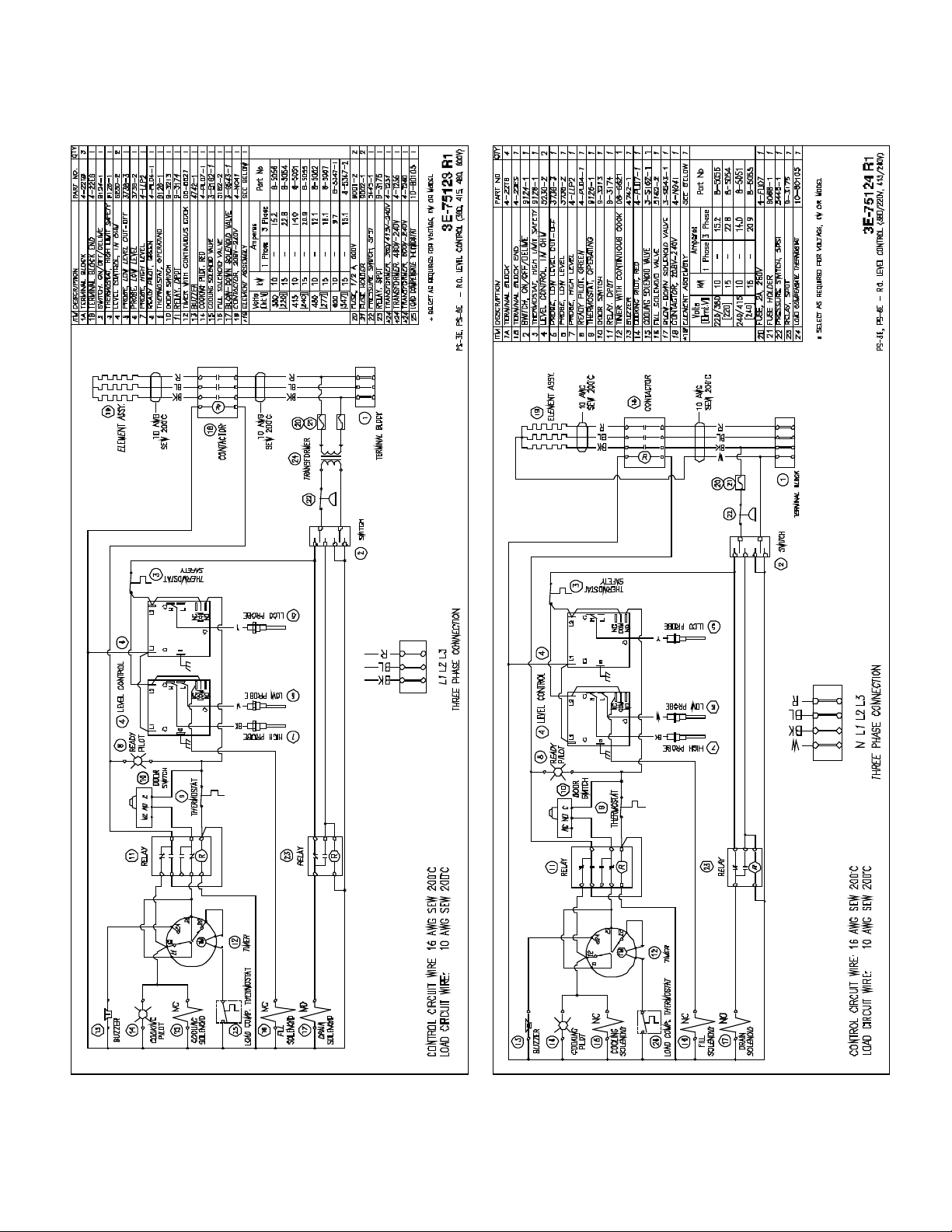
WIRING DIAGRAMS
Page 5

WIRING DIAGRAMS
Page 6

WIRING DIAGRAMS
Page 7
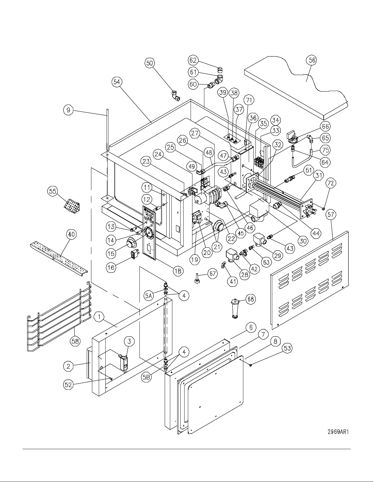
ILLUSTRATED PARTS LIST
AUGUST 1, 2014 7 PS-3E & PS-6E
Page 8
ITEM PART NOL DESCRIPTION PS-3E PS-6E
1A 97-6254 Door Assembly 1
97-6373 Door Assembly 1
1 97-6295 Door Frame 1
97-6227 Door Frame 1
2 97-6231 Door Handle Assembly 1 1
* 97-6235 Decal 1 1
* 97-6258 Door Handle 1 1
* 97-6259 Door Handle Plate 1 1
* 98-9165 Socket Set Screw, 1/4 - 20 x 1-3/4 2 2
* 97-5349 Socket Set Screw, 1/4 - 20 x 3/4 1 1
* 97-6260 Spacer 2 2
* 97-6297 Lock Washer, 1/4 2 2
* 97-6298 Hex Nut, 1/4 - 20 2 2
3 97-6232 Latch Assembly 1 1
4 97-6261 Door Bushing 4 4
5A 97-6734 Spacer - Upper 1 1
5B 97-6735 Spacer - Lower 1 1
6 97-6262 Door Panel 1
97-6230 Door Panel 1
7 97-6264 Door Gasket 1
97-6228 Door Gasket 1
8 97-6266 Gasket Plate, 3-pan 1
97-6229 Gasket Plate, 6-pan 1
9 97-6299 Hinge Rod 1
97-6364 Hinge Rod 1
*10 97-6300 Steam Diverter 2 2
11 97-6301 Actuator Complete With Retaining Rings 1 1
* 97-6191 Door Switch 1 1
12 97-6178 Striker 1 1
* 97-6302 Stainless Steel Washer 1 1
* 97-6650 Lock Washer 1 1
* 97-6651 Nut 1 1
13 97-6270 Pilot Light, Green 1 1
14 97-6271 Pilot Light, Red 1 1
**15 98-6046 Timer Dial 1 1
16 97-6272 Power Switch 1 1
* NOT SHOWN ** SELECT AS REQUIRED
AUGUST 1, 2014 8 PS-3E & PS-6E
Page 9

ITEM PART NOL DESCRIPTION PS-3E PS-6E
*17 97-6303 Label, De-Lime (Rear of Unit) 1 1
**18 97-6304 Control Decal 1
97-6305 Control Decal 1
19 97-6275 Component Mounting Board 1 1
**20 97-6276 Level Control Board, 10K OHM 1 1
97-6277 Level Control Board, 1M OHM 2 2
21 97-5048 Thermostat - Operating 1 1
97-6736 Dial 1 1
22 97-6278 High Limit Thermostat 1 1
23 97-6279 Relay - Single Pole, 240V 1 1
24 97-6280 Relay - Double Pole, 240V 1 1
25 08-6464 Timer, 230 VAC and 240 1 1
26 97-6307 Buzzer, 240V 1 1
**27 98-6189 Contactor - 4 Pole (208, 220, 240V) 1 1
97-5609 Contactor - 380, 415, 480, 600 Volt 1 1
28 97-6285 Cooling Solenoid, 240V, Metering 1 1
29 97-6308 Fill Solenoid, 240V 1 1
30 97-6283 Blow-down Solenoid, 240V 1 1
**31 97-6309 Element Assembly, 10 kW, 208V 1
97-6310 Element Assembly, 10 kW, 220/380V 1
97-6311 Element Assembly, 10 kW, 240/415V 1
97-6312 Element Assembly, 10 kW, 480V (287) 1
97-6313 Element Assembly, 10 kW, 600V (347) 1
97-6314 Element Assembly, 15 kW, 208V 1
97-6315 Element Assembly, 15 kW, 220/380V 1
97-6316 Element Assembly, 15 kW, 240/415V 1
97-6317 Element Assembly, 15 kW, 480V (287) 1
97-6318 Element Assembly, 15 kW, 600V (347) 1
32 97-6319 Element Gasket 1 1
**33 10-6963 Terminal Block, 208-240V, 10 kW, Black 4
98-6185 Terminal Block, 208-240V, 15 kW, White 4
* 97-6737 Terminal Rail, 208-240V, 15 kW 1
10-6963 Terminal Block, 380/220V 415/240V, Black 4 4
10-6963 Terminal Block, 380-600V, Black 3 3
**34 10-6962 End Section, Black 1 1
98-6186 End Section, 208-240V, 15 kW, White 1 1
* NOT SHOWN ** SELECT AS REQUIRED
AUGUST 1, 2014 9 PS-3E & PS-6E
Page 10

ITEM PART NOL DESCRIPTION PS-3E PS-6E
*35 97-5052 Ground Lug 1 1
97-6738 Earth I.D. Tag 1 1
36 97-6321 Steam Generator Tank 1 1
* 97-6322 Tank Cover 1 1
97-6323 Tank Gasket 1 1
37 97-6324 Probe - 5" Low Level Cut Off 1 1
38 97-6325 Probe - 4.25" Low Level 1 1
39 97-6326 Probe - 3.688" High Level 1 1
40 97-6177 Perforated Trough 1 1
41 98-6089 Elbow, 1/4 c x 1/8 MPT 1 1
42 97-6327 Tee, 3/8 c x 1/8 MPT 1 1
43 98-6123 Connector, 1/4 c x 1/8 MPT 1 1
44 97-6328 Connector, 1/2 c x 3/4 MPT 1 1
45 97-6208 Elbow, 1/2 c x 3/4 MPT 1 1
46 97-5619 Thermostat Fitting, 3/8 c x 3/8 MPT 1 1
47 97-6206 Union Coupling, 1/2 c 1 1
48 97-6329 Right Hand Steam Jet Tube 1 1
* 97-6330 Left Hand Steam Jet Tube 1 1
49 97-6331 Elbow, 1/2 c x 1/4 MPT 2 2
50 97-6207 Elbow, 1/2 c 1 1
51 97-6226 Water Connection, 3/8 c 1 1
52 97-6739 Screw, 10-32 x 1/2 SS 6 6
53 97-6233 Screw, (Special), 10-32 x 1/2 6 8
54 97-6332 Left Hand Side and Back 1
54 97-6333 Left Hand Side and Back 1
55 97-6334 Compartment Strainer 1 1
56 97-6335 Top 1 1
**57 97-6336 Side Panel 1
97-6337 Side Panel 1
**58 97-6338 Rack Slides 2
97-6339 Rack Slides 2
*59 97-6340 Rack Pin Assembly 4 4
60 97-6341 Brass Nipple, 1/2 -14 1 1
61 97-6342 Brass Elbow, 1/2 -14 1 1
62 97-6740 Brass Plug, 1/2 - 14, Hex Head 1 1
63 97-6344 Connector, 3/8 c x 1/8 MPT 1 1
* NOT SHOWN ** SELECT AS REQUIRED
AUGUST 1, 2014 10 PS-3E & PS-6E
Page 11
ITEM PART NOL DESCRIPTION PS-3E PS-6E
64 97-6591 Connector, 3/8 c x 1/8 FPT 1 1
65 97-6346 Elbow 90°, 3/8 c x 3/8 MPT 1 1
66 97-6347 Pressure Switch 1 1
67 97-6348 Leveler 4 4
68 97-6211 Adjustable Leg, Optional 4 4
* **69 97-6186 Fuse, 2 Amp., 250V (208, 240V) 2 2
97-6186 Fuse, 2 Amp., 250V (220, 220/380, 240/415) 1 1
* ** 98-6188 Fuse, 1/2 Amp, 600V (380, 415, 480, 600V) 2 2
97-5864 Fuse Holder (208, 240V) 2 2
97-5864 Fuse Holder (220, 220/380, 240/415V) 1 1
98-6187 Fuse Holder (380, 415, 480, 600V) 2 2
* **70 97-5616 Transformer, 380-220V, 50/60 Hz, 100VA 1 1
97-5616 Transformer, 415-240V, 50/60 Hz, 100VA 1 1
97-5613 Transformer, 480-240V, 60 Hz, 100VA 1 1
98-6191 Transformer, 600-240V, 60 Hz, 100VA 1 1
71 97-6663 Hex Blot, 5/16-18 x 1 SS 2 2
72 97-6298 Hex Nut, 1/4 - 20 SS 4 4
*73 97-6349 “Y” Strainer, Optional 1 1
*74 97-6741 Wire Harness 1 1
75 97-6351 Copper Tube, 3/8 1 1
* NOT SHOWN ** SELECT AS REQUIRED
AUGUST 1, 2014 11 PS-3E & PS-6E
 Loading...