

Market Forge PS-3E Installation Manual
PREMIERE SERIES
ELECTRIC CONVECTION STEAMERS
INSTALLATION - OPERATION - MAINTENANCE
MODELS
PS-3E
PS-6E
44 Lakeside Avenue, Burlington, Vermont 05401 USA
Telephone: (802) 658-6600 Fax: (802)864-0183
www.mi.com PN 14-0264 Rev A (7/14)
© 2014 - Market Forge Industries Inc.

Your Service Agency’s Address:
Model
Serial number
Oven installed by
Installation checked by

IMPORTANT
TABLE OF CONTENTS
WARNING: Improper installation, adjustment, alternation,
service or maintenance can
cause property damage, injury or death. Read the installation, operation and maintenance instructions thoroughly
before installing or servicing
this equipment.
FOR YOUR SAFETY
Do not store or use gasoline or
other ammable vapors or liquids in the vicinity of this or any
other appliance.
The information contained in this
manual is important for the proper installation, use, and maintenance of this oven. Adherence
to these procedures and instructions will result in satisfactory
baking results and long, trouble free service. Please read
this manual carefully and retain
it for future reference.
INSTALLATION
Service Connections ..................................................... 2
Installation Instructions ................................................... 3
Testing Procedures ....................................................... 6
OPERATION
Operating Instructions .................................................... 7
Control Description ................................................... 7
Cooking with the Steamer ............................................. 7
Shut Down........................................................... 7
Suggested Cooking Guidelines ............................................ 9
MAINTENANCE
Cleaning ............................................................... 11
Condenser Maintenance ................................................. 12
ERRORS: Descriptive, typographic or pictorial errors are
subject to correction. Specications are subject to change
without notice.

Service Connections
SERVICE CONNECTIONS
GW Generator Water - 3/8” (10mm) OD tubing at 25-50 PSI.
CW Cold Water - 3/8” (10mm) OD tubing at 25-50 PSI.
D Drain - 1” (25mm) IPS piped to open floor drain. NO
SOLID CONNECTION TO FLOOR DRAIN. NO BENDS
OR ELBOWS.
EC Electrical Connection - 1-1/8” (29mm) electric connection
to controls.
GW
D
1.75 (44)
27.50 [699]
15.00 [381]
3.00 [76]
1.75 [44]
CW
EC
ELECTRICAL CHARACTERISTICS
AMP/PHASE
SINGLE PHASE
MODEL kW
PS-3E 10
PS-6E 15
MODEL kW
PS-3E 10
PS-6E 15
208V 220V 240V
48 46 42
72 69 63
AMP/PHASE
THREE PHASE
208V 240V 380V 415V 480V 600V
28 24 16 14 12 10
42 36 23 21 18 15
CAUTION:
Before connecting water to this unit, water supply should be analyzed to make sure hardness is no greater than 2.0 grains and pH
level is within the range of 7.0-8.5. Water which fails to meet these
standards should be treated by installation of water conditioner.
EQUIPMENT FAILURE CAUSED BY INADEQUATE WATER
QUALITY IS NOT COVERED UNDER WARRANTY.
17.00 [432]
D
24.00 [610]
20.00 [508]
EC
GW
PS-3E
1.50 [38]
12.50 [318]
CW
PS-6E
19.00 [483]
DIMENSIONS ARE IN INCHES [MM]
1/2 NPT DELIME INLET
23.50 [597]
Figure 1
D
1.00 [25]
2.00 [51]
PS-3E
PS-6E
15.13 [384]
21.62 [549]
4.02 [102]
INSTALLATION
2
Installation Instructions
GENERAL
The PS-3E and PS-6E steamers are single compartment
electric pressureless steam cookers with an internal electric steam generator that maintains standby water temperature at approximately 205°F. PS-3E is rated 10 kW.
PS-6E is rated 15 kW.
At high altitude locations a lower temperature is required
to achieve atmospheric steaming. Contact your autho-
rized service ofce to have the thermostat adjusted if the
steamer will be operated at high altitudes.
UNPACKING
This steamer was inspected before leaving the factory.
The transportation company assumes full responsibility
for safe delivery. Immediately after unpacking the steamer, check for possible damage. If the steamer is found to
be damaged after unpacking, save the packaging material and contact the carrier within 15 days of delivery.
Prior to installation, verify that the electrical service agrees
with the specications on the machine data plate which is
located on the left side panel.
LOCATION
Allow space for plumbing and electrical connections.
Minimum clearances are 0” on the sides and 6” (152 mm)
on the back for proper air circulation. Allow adequate access for operating and servicing the steamer, 36” (915
mm) at the front of the steamer and 15” (381 mm) above
the steamer.
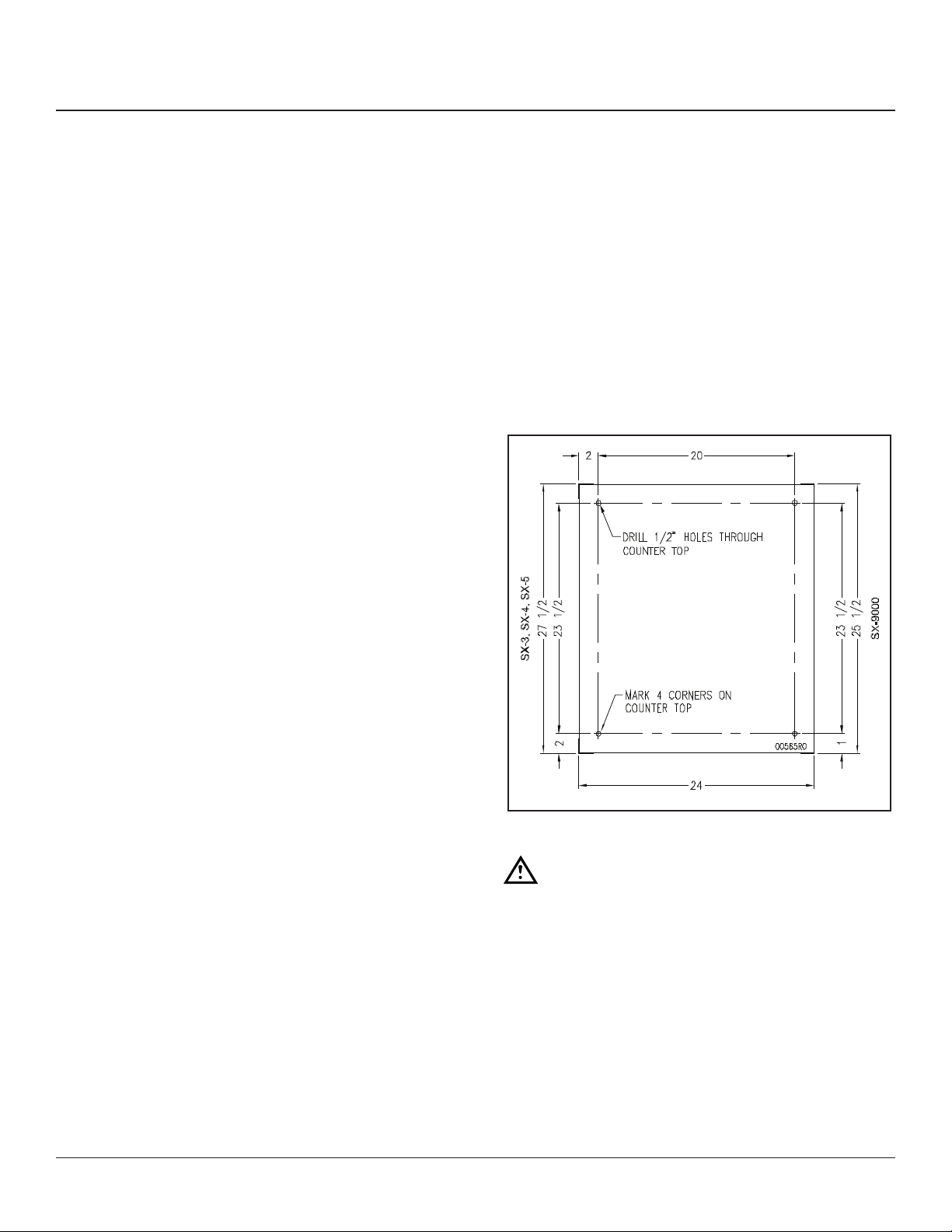
ANCHORING STEAMER (WITHOUT LEGS)
1. Place steamer in the desired location on the levelled
counter top and mark four corners. Remove the
steamer and drill 1/2” holes as indicated in “Figure 2”.
2. Apply a bead of RTV or other equivalent sealant
around bottom perimeter edge of the steamer. If anchoring the steamer, this bottom seal is necessary to
meet NSF requirements.
3. Set steamer on counter and bolt down securely with
3/8 - 16 bolts (not supplied).
STACKING KIT
Follow instructions in the stacking kit when installing
stacked convection steamers.
LEVELING FEET (STANDARD) OR 4” ADJUSTABLE
LEGS (OPTIONAL)
Thread the four 2” levelling feet shipped in a bag inside
the steamer cabinet into the threaded holes on the bottom corners of the steamer. Or, thread the four optional
4” adjustable legs into the threaded holes on the bottom
corners of the steamer.
LEVELING
Using a spirit level or pan of water in the bottom of the
steamer, adjust the levelling feet or the feet on the adjustable legs to level the steamer front-to-back and sideto-side. After the drain is connected, check for level by
pouring water onto the oor of the compartment. All water
should drain through the opening at the back of the compartment cavity.
Figure 2
WARNING
Disconnect the power supply to the appliance
before cleaning or servicing.
Make electrical connection through the 1-1/8” (29 mm) diameter hole provided using 3/4” (19 mm) trade size conduit. Refer to the wiring diagram located inside the right
side panel. Use 90°C minimum insulated wire.
3
INSTALLATION
 Loading...