

Page 1
0
OWNER’S MANUAL
WARNING:
IMPROPER INSTALLATION, ADJUSTMENT,
ALTERATION, SERVICE OR MAINTENANCE CAN CAUSE
PROPERTY DAMAGE, INJURY OR DEATH. READ THESE
INSTALLATION, OPERATION AND MAINTENANCE
INSTRUCTIONS THOROUGHLY BEFORE INSTALLING
OR SERVICING THIS EQUIPMENT.
Form Number: S-2110 REV. D 04/14
Printed in USA 35 Garvey Street, Everett, MA 02149
Telephone (617) 387-4100, (866) 698-3188, Fax (617) 387-4456, (800) 227-2659
custserv@mfii.com, www.mfii.com
WARNING:
DO NOT UNDER ANY CIRCUMSTANCE CONNECT THE
EXHAUST DRAIN LINE DIRECTLY TO A SEWER LINE.
WARNING:
DO NOT HOSE DOWN UNIT AS IT MAY CONTAIN
ELECTRICAL COMPONENTS.
CAUTION: Before connecting water to this unit, water
supply should be analyzed to make sure hardness is
no greater than 2.0 grains and pH level is within the
range of 7.0-8.5. Water which fails to meet these
standards should be treated by installation of water
conditioner or filter system. EQUIPMENT FAILURE
CAUSED BY INADEQUATE WATER QUALITY IS NOT
COVERED UNDER WARRANTY.
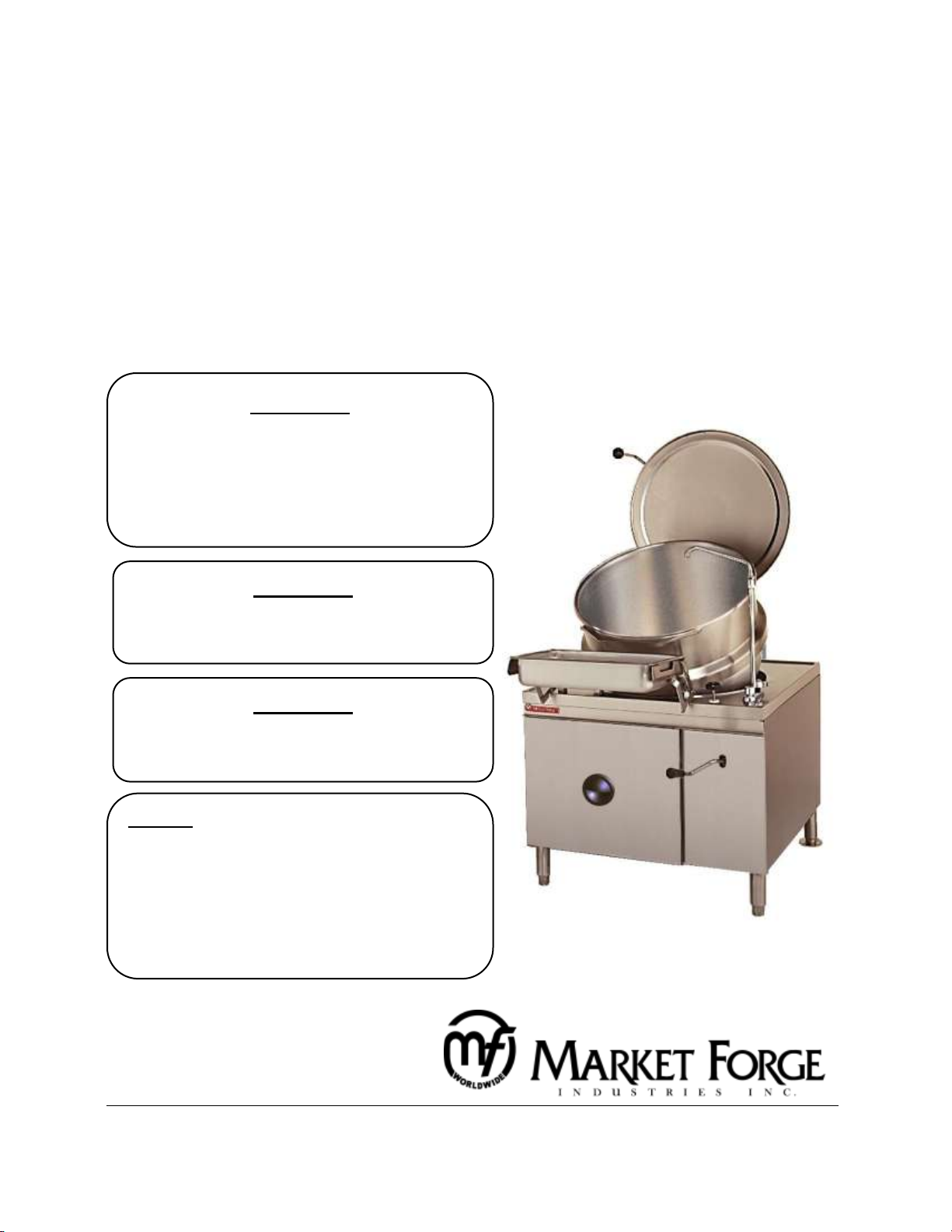
Modular Tilting Direct Steam Jacketed Kettle
MODELS: □ MT-25
□ MT-40
□ MT-60
Page 2

1
Table of Contents
INTRODUCTION ......................................................... 1
INSTALLATION INSTRUCTIONS
SERVICE CONNECTIONS – MT-25EO, MT-40EO ......... 2
SERVICE CONNECTIONS – MT60EO ........................... 3
WIRING DIAGRAM ..................................................... 4
SCHEMATIC ................................................................ 5
OPERATING INSTRUCTIONS
START-UP ................................................................... 6
CONTROL PANEL ........................................................ 6
OPERATING THE STEAM BOILER ................................ 6
COOKING ................................................................... 7
INSTALL PAN SUPPORT .............................................. 8
SHUT-DOWN .............................................................. 9
DAILY CLEANING ........................................................ 9
COOKING GUIDE ................................................ 10-12
TROUBLESHOOTING .......................................... 13-15
ADJUSTMENTS
REPAIR & REPLACE ................................................... 16
PRESSURE CONTROL SWITCH ADJUSTMENTS ......... 16
COLD WATER CONDENSER ADJUSTMENT ............... 17
LID COUNTERBALANCE ADJUSTMENT ................ 17-18
HEATING ELEMENT REPLACMENT ........................... 18
WATER CONTROL BOARD TESTING PROCEDURE .... 19
WATER LEVEL CONTROL .......................................... 20
CIRCUIT OPERATION ................................................ 20
WATER LEVEL CONTROL OPERATION ...................... 20
LOW WATER CUTT OFF ............................................ 20
WATER LEVEL CONTROL MAINTENANCE AND
CLEANING ................................................................ 21
PROBE CLEANING .................................................... 21
DRAW OFF VALVE REPAIR ........................................ 22
COMMON LEAK REPAIRS ......................................... 22
VALVE SEAT LAPPING ............................................... 22
TILTING MECHANISM REPAIR .................................. 22
LIFT SCREW ASSEMBLY REMOVAL ........................... 22
GENERAL INSPECTION AND CLEANING .................... 23
CRANK SLEEVE REPLACEMENT ................................ 23
TILTING MECHANISM LUBRICATION ....................... 23
MAINTENANCE
PREVENTIVE MAINTENANCE ................................... 24
DAILY CLEANING ...................................................... 24
APPLICATION INSTRUCTIONS – TOTAL CONCEPT
DESCALER ............................................................ 25-26
ILLUSTRATED PARTS LIST
PRESSURE SWITCHES ............................................... 27
DRAIN ASSEMBLY ..................................................... 28
TILTING MECHANISM .............................................. 29
PISTON ASSEMBLY ................................................... 30
VALVE AND FAUCET ................................................. 31
LOW WATER CUT OFF .............................................. 32
CRANK SHAFT........................................................... 33
BOILER BASE ASSEMBLY .......................................... 34
ELECTRICAL COMPONENTS ...................................... 35
VALVE ASSEMBLY ..................................................... 36
KETTLE JACKET ASSEMBLY ....................................... 37
Page 3

1
INTRODUCTION
This service and parts manual contains descriptive and maintenance information (including
trouble shooting guide) for modular kettles. A Parts list is also included in which each
replacement part is identified and shown in an accompanying illustration unless otherwise
stated.
Description:
Market Forge tilting direct steam jacketed kettles of three capacities, each mounted in a
modular stainless steel cabinet.
Double wall construction around the lower half of the kettle forms a surrounding chamber into
which steam is introduced as a source of heat for cooking.
Steam input plumbing is equipped with a manual control valve. Condensate is removed through
a steam trap connecting with the kettle drain plumbing assembly. A swivel spout, hot-cold
combination faucet provides a source of water for addition to the kettle for cooking and
cleaning.
An optional 12” spacer unit with faucet and sink may be used instead of the standard built-in
faucet.
Large capacity kettles are fitted with heavy duty tilting mechanisms operated by removable
hand crank. Each model is equipped with a pan support which maintains continuous alignment
of serving pans under the pouring spout at all levels of kettle elevation. Counterbalanced
hinged lids cover the kettles in the lowered position. All are plumbed for direct connection to a
remote steam source. An optional cold water circuit to the steam jacket is available for use with
all models for quick cooling of foods after cooking.
Applicable model designation includes: MT-25 (25-gallon) – 36” wide (914mm) cabinet base,
MT-40 (40-gallon) – 36” wide (914mm) cabinet base, and MT-60 (60-gallon) – 48” wide
(1219mm) cabinet base.
Service:
Required service, both repair, replacement, and adjustment is explained in Adjustments section
of this manual. Other service help can be found in the Trouble Shooting and Maintenance
sections of this manual. Should repairs be required, a network of Authorized Service Agents is
available to assist with prompt service. A current list of Authorized Service Agencies may be
obtained by contacting Market Forge direct of going on our website:
Call us toll free at (866) 698-3188 or (617) 387-4100
Email us at custserv@mfii.com or go to http://www.mfii.com/company/service
The model and serial number must be referenced when corresponding with Market Forge.
These numbers can be found on the data plate located on the upright frame behind the cabinet
base door. If you require further assistance in obtaining these numbers, please contact us
directly.
Page 4
2
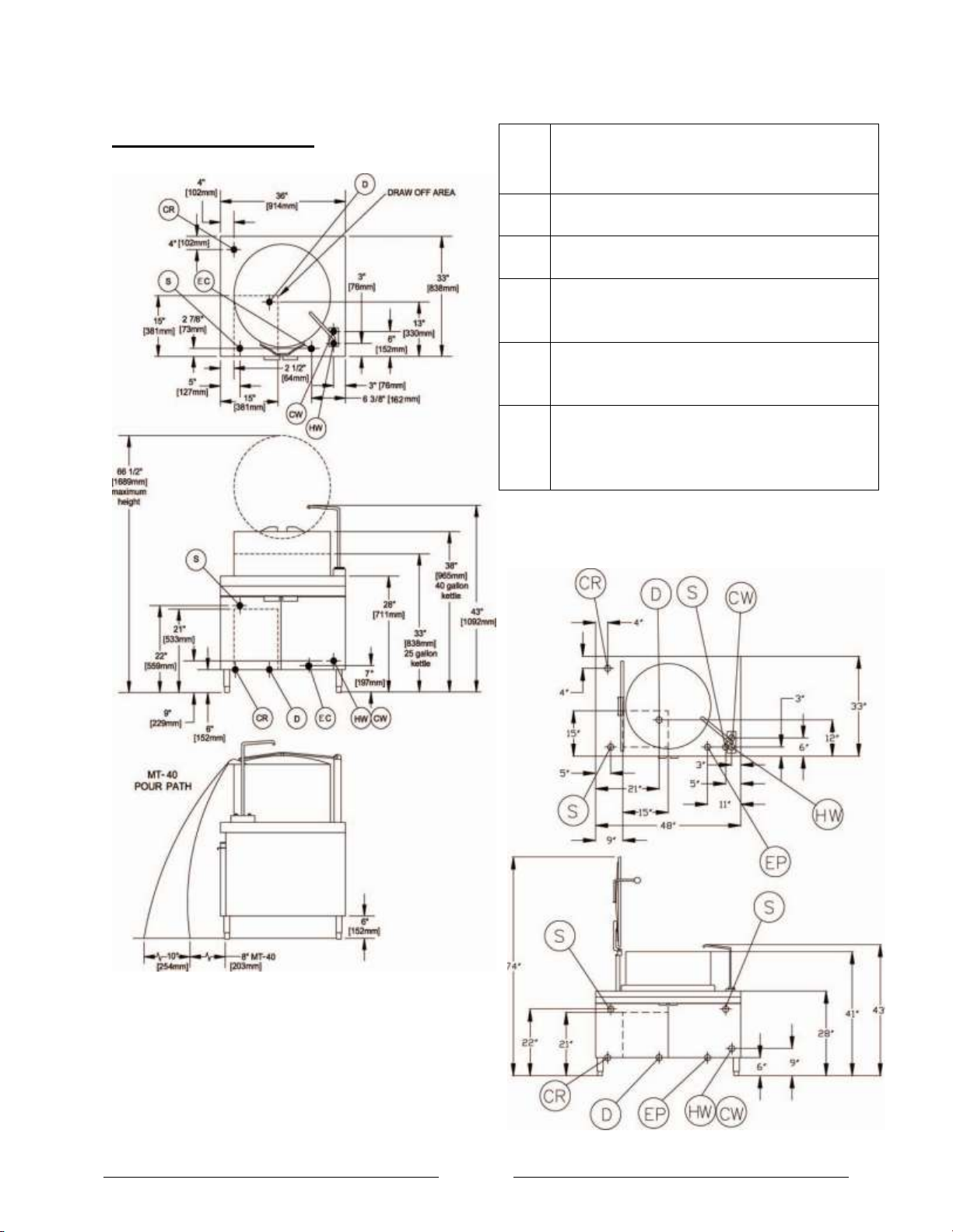
S
Steam Supply - 3/4” (19mm) NPT, 15 P.S.I
(1.0 kg/cm2) minimum; 30 P.S.I (2.1 kg/cm2)
maximum.
HW
Hot Water - 3/8” (10mm) OD tubing to hot
water for kettle fill faucet.
CW
Cold Water - 3/8” (10mm) OD tubing to cold
water for kettle fill faucet.
D
Drain - Pipe full 2” NPT (51mm) to flush floor
drain. Do not make solid connection to
drain.
CR*
Condensate Return - 1/2” I.P.S. (13mm)
connection for condensate return from
kettle when specified.
EC*
Electrical Controls - 115 volts AC, 60 Hz, 40
watts, 1/2” (13mm) conduit connection or
equivalent. Use wire suitable for at least
90OF. Draws less than 1 Amp with power lift.
* Optional.
MT-60
SERVICE CONNECTIONS:
MT-25 and MT-40
INSTALLATION INSTRUCTIONS
NOTES:
1. Pressure-reducing valve is required if incoming
pressure exceeds 30 PSI (2.1 kg/cm2).
2. Recess area for kettle draw-off (dotted line) must
be kept free of all piping and connections.
3. PVC and CPVC pipe are not acceptable materials for drains.
4. Separate height for 25-, 40-, and 60-gallon kettles.
Page 5

3
OPERATION INSTRUCTIONS
CAUTION: FOOD MUST EITHER BE REMOVED FROM THE KETTLE IMMEDIATELY OR COOLED BY
A KETTLE JACKET COOLING SYSTEM TO PREVENT OVER COOKING.
OPERATING CONTROLS & INDICATORS
All of the controls required to operate the kettles are listed in table on page 4, together with an
explanation of location and a short functional description.
OPERATING PROCEDURE
All kettles must be supplied with steam from a generator which is remotely located. Consult steam
generator information or instruction plate and complete all start-up instructions. Proceed with
kettle operating procedure as follows:
1. Check pressure gauge of steam supply source to insure steam input is at 15 PSI (1.0 kg/cm
For direct connected steam, turn on external steam supply valve.
2. Check that Draw-Off Valve is tightly closed.
3. Lift kettle lid and place either a Solid or Perforated Drain Disc over the drain inside kettle.
Use solid disc to retain liquids; perforated to strain liquids from food.
4. Load kettle with foods to be cooked.
5. Add water for cooking by swinging spout over kettle and using Combination Faucet.
6. Turn Steam Control Valve to full counter-clockwise position to heat kettle content to an
initial rapid boil.
7. Adjust subsequent cooking temperature by turning Steam Control Valve. Turn clockwise to
reduce heat and counter-clockwise to increase.
8. Close Steam Control Valve (full clockwise position) when cooking is complete.
2
).
9. Remove food from tilting kettles. With Pan Support mounted (see section pan support
mounting tilting kettles, on page 4), food pan in support, and Crank installed in front of
cabinet, turn crank clockwise to elevate kettle for pouring. (Tilting mechanism is infinitely
adjustable and non-coasting in kettle elevation and lowering). Liquid foods may also be
removed by use of the Draw-Off Valve as explained in step 11 for stationary kettles.
10. Complete cleaning procedures (see cleaning procedure section below).
CLEANING PROCEDURE
As with cleaning food soil from any cookware, an important part of kettle cleaning is to prevent
foods from drying on. For this reason cleaning should be completed immediately after cooked
foods are removed. If time can not be allotted for immediate complete cleaning the kettle should
be soaked by filling it with warm detergent water solution.
Cleaning
1. Wash the kettle with a long handled nylon bristle kettle brush (Part No. 10-5308).
2. Empty wash water by opening Draw-Off Valve over Swing Drain.
3. Remove Drain Disc (solid or perforated) from inside kettle and clean.
4. Rinse kettle by flushing with hot water from the Swivel Spout.
5. Loosen hex nut on Draw-Off Valve and carefully remove all parts. Clean and reassemble (see
figure 11, on page 17).
Page 6
4
OPERATION INSTRUCTIONS
6. Rotate Swing Drain to left and push up off drain assembly. Clean drain and screen.
Reassemble on kettle.
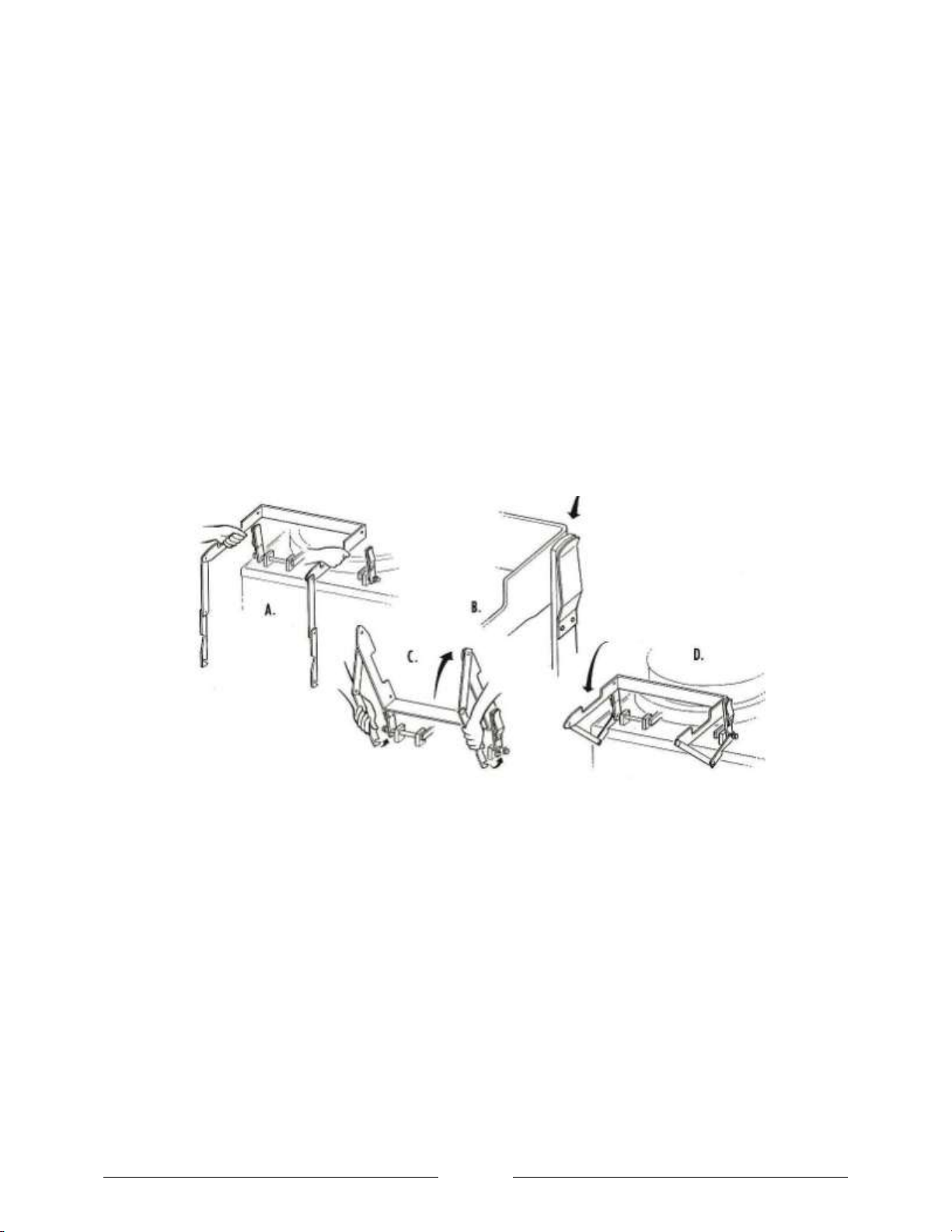
Pan Support Mounting Tilting Kettles
For convenience during cooking, the pan support need not be installed until needed for removing
food from the kettles. To Insure correct operation and to prevent spills the support must be
securely installed as shown in Figure 1 below and as explained below:
1. Hold the pan support in front of the upright as shown at A.
2. Place the stud of the left-hand support upright into the hole in the left side of the pan
support. Then push the right side of the support in until it engages the spring loaded pin of
the right-hand support upright, shown at B.
3. Rotate the pan support upward (C) and engage the slotted ends of the support links in the
studs at the base of each support upright as in D.
The removal procedure is the reverse of installation with the exception that in step 2 support
upright springs must be pushed out to release the support from studs.
Figure 1, Mounting Pan Support
Page 7
5
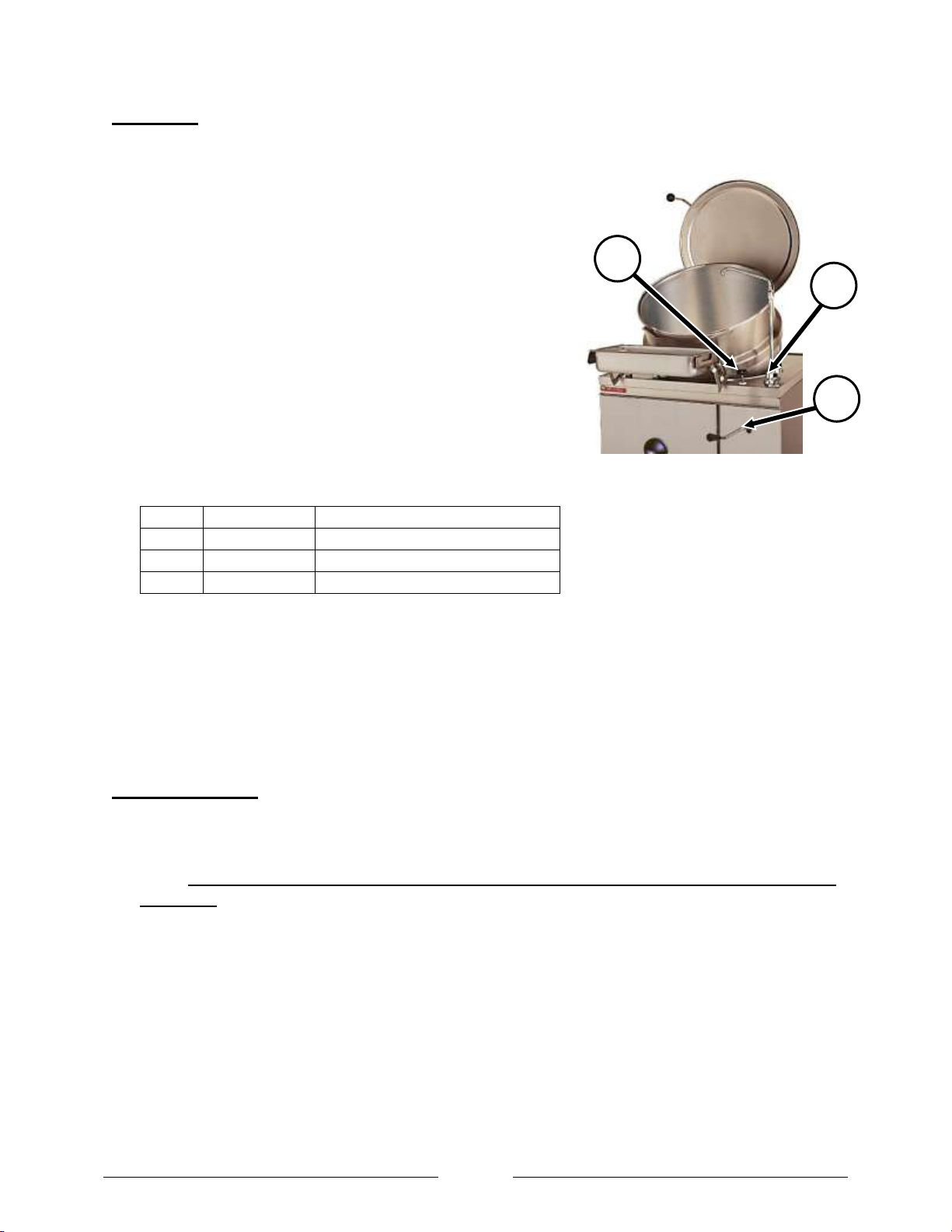
Figure 2, Steam Jacketed Kettle
1 3 2
OPERATION INSTRUCTIONS
ITEM
PART NO.
DESCRIPTION
1
10-7680
HOT AND COLD FILL FAUCET
2
10-5242
STEAM CONTROL VALVE
3
98-1568
CRANK HANDLE (MANUAL TILT)
COOKING:
1. Check pressure to ensure that boiler is up to operational pressure of 10-12 PSI (0.7-0.8kg/cm
2. Check that draw-off valve is tightly closed by turning it
clockwise.
3. Place solid disc or perforated disc in drain opening
inside kettle.
NOTE: Use solid disc if liquid is to be retained; use
perforated disc if liquid is to be discarded.
4. Fill kettle to desired level with food to be cooked or
water from hot and cold fill faucet (Figure 2, No. 1).
NOTE: Refer to Cooking Guide (page 10) for cooking
procedures that address individual food products.
5. Turn kettle steam control valve (Figure 2, No. 2)
counterclockwise to full ON position for faster results.
2
).
NOTE: The volume of steam going into the kettle jacket can be controlled at any time by adjusting
the kettle steam control valve in either direction.
6. When food is cooked, turn steam control valve clockwise to stop steam flow. Remove food
immediately to prevent over cooking.
7. Prior to removing foods from kettle, the pan support should be placed in a position to establish
a firm support for receiving pan.
DAILY CLEANING:
1. Fill kettle with water and mild detergent immediately after removing food from kettle.
2. Scrub kettle interior with a nylon brush.
NOTE: NEVER SCRAPE KETTLE INTERIOR WITH METAL TOOLS, STEEL SCOURING PADS OR ABRASIVE
CLEANERS. Scratches will result, which will ruin the kettles general appearance and make it harder to
clean and maintain in a sanitary condition.
3. Loosen food which is stuck to kettle by allowing it to soak. Also, a small amount of steam may
help.
4. Position swing drain under draw-off valve. Open draw-off valve to drain soapy water.
5. Wipe down exterior, rinse and dry. Avoid getting water into electrical controls.
Page 8

6
OPERATION INSTRUCTIONS
WARNING: DO NOT HOSE DOWN UNIT AS IT CONTAINS ELECTRICAL COMPONENTS.
6. Remove strainer from inside kettle. Wash and rinse thoroughly.
7. Disassemble draw-off valve by first turning valve handle counterclockwise. Then, turn hex nut
counterclockwise until valve handle and stem are free.
8. Wash inside of draw-off valve with a nylon brush.
9. Rinse kettle valve interior and reassemble valve.
NOTE: Leave draw-off valve open when kettle is not in use.
10. Remove swing drain and its strainer. Wash, rinse and replace.
Cooking Facts for Steam Jacketed Kettles:
A Steam Jacketed Kettle is a stainless steel kettle jacketed or encapsulated by a second outer kettle,
creating a space between the two kettles. Cooking is achieved by allowing steam to flow within this
space. The jacket or outer kettle usually covers 2/3 of the inner kettle, although some kettles are fully
jacketed
The steam flowing in the space between the kettles condenses on the cold inner kettle wall and releases
heat through the wall to the food in the kettle. The condensate drains to the bottom of the kettle and is
released through a steam trap without any loss or variation in steam pressure. The amount of steam
allowed to flow Into the Jacket controls the heat of the kettle. In use, the Steam Jacketed Kettle provides
consistent heat distribution and is energy efficient using steam only to maintain pressure, unlike top of
the range cooking in which energy (gas or electricity) is used during the entire cooking process.
Steam Jacketed Kettles can sauté, simmer, or boil a wide variety of products, such as soups, gravies,
sauces, pasta, stews, mixed casserole type dishes, vegetables, shellfish, cereals, hot beverages, and
puddings. A Steam Jacketed Kettle will not burn foods. However, foods that caramelize at relatively low
temperatures, such as eggs and milk based products, will coat and cook onto the sides of the kettle.
Care should be taken to use the smallest flow of steam, to lessen the possibility of scorching these
products. To achieve this, allow products to come up to desired temperature, stirring frequently, then
turn off steam flow and gradually turn on a small flow of steam - just enough to allow food to cook.
Steam Jacketed Kettles eliminate much range top cooking and greatly reduce the number of pots and
pans required. Because they are made of stainless steel, they are durable, non-porous and easy to clean.
Estimate actual cooking capacity of Steam Jacketed Kettles at 3,4 of its volume, to allow stirring
without spillage.
Plan an adequate drain arrangement. This is very important for ease of use and to minimize wet
floors. A grated gutter type drain located in front of the kettles is preferred as it eliminates the
hazards of tripping over a curb or stumbling into a recessed drain area.
Locate a source of water (swivel faucet or flexible hose type) near the kettle to facilitate filling
and cleaning.
Cover products whenever possible to save energy. Covered water boils 25 to 30% faster.
Use the tangent draw off valve to drain off products from the kettle such as sauces and
puddings, or cooking liquids that are being discarded (as in the case of the water used to cook
pasta)
Page 9

7
OPERATION INSTRUCTIONS
ITEM
COOKED PORTION
SIZE
KETTLE SIZE
25 GALLON
(95 LITERS)
40 GALLON
(150 LITERS)
60 GALLON
(225 LITERS
BEVERAGES
Cocoa or Coffee
6 oz or 3/4 cup (180 ml.)
Yield: 20 gal. (75 l.)
Portions = 425
Yield: 35 gal. (132 l.)
Portions = 745
Yield: 50 gal. (190 l.)
Portions = 1065
BREAKFAST FOODS
Cereal
6 oz or 3/4 cup (180 ml.)
Amt. Raw: 20# (9 kg.)
Portion =
270
Amt. Raw: 36 #
(16.3 kg)
Portion =
480
Amt. Raw: 48 #
(21.7 kg.)
Portion =
640
Scrambled Eggs
4 oz or 2 eggs each
(115 g.)
Eggs: 90 dz. 18 gal.
(120 l.)
Portions = 540
Eggs:
160 dz.
, 32 gal.
(166.5 l.)
Portions =
960
Eggs: 220
dz.
44 gal.
Portions = 1320
DESSERTS
Cornstarch
Pudding
4 oz. or 1/2 cup
(120 ml.)
Yield: 17 gal. (64.3 l.)
Portions = 545
Yield: 30 gal. (113.5l.)
Portions = 960
Yield: 40 gal. (151 l.)
Portions = 1280
Gelatin
4 oz. or 1/2 cup (120 g.)
Yield: 20 gal. (75 l.)
Portions = 640
Yield: 35 gal. (132 l.)
Portions = 1120
Yield: 50 gal. (190 l.)
Portions = 1600
MAIN ENTREES
*
Macaroni, Beef
and Tomato
6 oz. or 3/4 cup
(170 g.)
Yield: 17 gal. (65 l.)
Portions = 360
Yield: 30 gal. (113 l.)
Portions = 640
Yield: 45 gal. (170 l.)
Portions = 960
Baked Beans
5 oz. or 2/3 cup
(140 g.)
Yield: 20 gal. (75 l.)
Portions = 500
Yield: 32 gal. (120 l.)
Portions = 800
Yield: 50 gal. (190 l.)
Portions = 1250
Beef Stew
8 oz. or 1 cup
(225 g.)
Yield: 17 gal. (65 l.)
Portions = 270
Yield: 30 gal. (113 l.)
Portions = 480
Yield: 45 gal. (170 l.)
Portions = 725
Macaroni and
Cheese
5 oz. or 2/3 cup
(140 g.)
Yield: 17 gal. (64 l.)
Portions = 425
Yield: 30 gal. (113 l.)
Portions = 750
Yield: 45 gal. (170 l.)
Portions = 1125
Turkey A La King
4 oz. or 1/2 cup
(115 g.)
Yield: 17 gal. (64 l.)
Portions = 545
Yield: 30 gal. (113 l.)
Portions = 960
Yield: 45 gal. (170 l.)
Portions = 1280
MISCELLANEOUS
Gravy/Sauce
2 oz. or 3/4 cup
(60 ml.)
Yield: 20 gal. (75 l.)
Portions = 1200
Yield:
35 gal. (132 l.)
Portions = 2000
Yield:
50 gal. (190 l.)
Portions = 3000
Remove the tangent draw off valve after each use for cleaning, using a brush to clean draw off
as bacteria will readily multiply in this area if it is not thoroughly cleaned.
Use the optional solid kettle disk when product is not going to be dispensed through the draw
off valve, and the perforated disk when draining off liquids through the draw off valve and
retaining the solid product in the kettle.
COOKING CHART
This chart merely shows single load capacities as it is felt that in most cases the kettle would be used
only once per meal.
* All main entree figures are given in terms of raw ingredients.
Page 10

8
OPERATION INSTRUCTIONS
ITEM
COOKED PORTION
SIZE
KETTLE SIZE
25 GALLON
(95 LITERS)
40 GALLON
(150 LITERS)
60 GALLON
(225 LITERS
MACARONI AND RICE
Noodles
4 oz. or 3/4 cup
(115 g.)
Amt. Raw:
20 gal.
(9kg.)
Portions = 220
Amt. Raw:
35 #
(15.8kg.)
Portions = 385
Amt. Raw:
50 #.
(22.6kg.)
Portions = 555
Rice
3 oz. or 1/2 cup
(85 g.)
Amt. Raw:
20 gal. (9
kg.)
Portions = 320
Amt. Raw:
35 # (15.8
kg.) Portions = 560
Amt. Raw:
50 #. (22.6
kg.) Portions = 800
Spaghetti or
Macaroni
4 oz. or 3/4 cup
(115 g.)
Yield: 20 gal. (9 kg.)
Portions = 320
Amt. Raw:
35 #
(15.8kg.)
Portions = 385
Amt. Raw:
50 #.
(22.6kg.)
Portions = 555
SOUPS
Basic Cream Soup
6 oz. or 3/4 cup
(180 ml.)
Yield: 20 gal. (75 l.)
Portions = 400
Yield:
35 gal. (132 l.)
Portions = 700
Yield:
50 gal. (190 l.)
Portions = 1000
Broth Type Soup
8 oz. or 1 cup
(240 ml.)
Yield: 20 gal. (75 l.)
Portions = 325
Yield:
35 gal. (132 l.)
Portions = 560
Yield:
50 gal. (190 l.)
Portions = 800
VEGETABLES
Fresh
4 oz. or 1/2 cup
(115 g.)
Amt.Raw: 80#.
(36.3kg.)
Portions = 335
Amt. Raw:120 # (54.4
kg.)
Portions = 500
Amt.Raw: 180#. (81.6
kg.)
Portions = 750
Frozen Loose
Pack
4 oz. or 1/2 cup
(115 g.)
No. Of Packages: 50
Portions = 550
No. Of Packages: 80
Portions = 880
No. Of Packages: 120
Portions = 1320
Frozen Solid Pack
4 oz. or 1/2 cup
(115 g.)
No. Of Packages: 25
Portions = 275
No. Of Packages: 40
Portions = 440
No. Of Packages: 60
Portions = 660
COOKING CHART (Continued)
Page 11

9
ADJUSTMENTS
Figure 3, Ball Nut Assembly
General Inspection & Cleaning
The screw assembly should run smoothly throughout the entire stroke. If operation is not uniform,
remove the screw assembly and proceed as follows:
1. Inspect screw shaft for accumulation of foreign
matter in the ball grooves.
2. Using cleaning fluid or solvent, remove dirt from
ball grooves. Be sure to flush the ball nut
assembly thoroughly.
3. Cycle the ball nut along the screw shaft several
times. Then, wipe with a dry, lint less cloth and
lubricate immediately.
Cabinet Exterior Removal
Side and rear panels of all cabinets in which kettles are
mounted are easily removed without the use of tools.
Each panel is grasped at the bottom edge and lift up and
out towards you to release it from the panel mounting
brackets
Replacement is completed by pushing panel up under
cabinet top allow hook to fall in place at the bottom
until panel mounting brackets are engaged. Door may be
removed to improve access to cabinet interior for
repairs.
The two flat head screws and nuts holding cabinet hinge are removed and the door lifted out. When
doors are remounted the final tightened position of hinge determines the alignment of the door and
must be set with care.
Draw-Off Valve – Common Leak Repairs
To repair a valve leak, the source must first be determined. Leaks from around the valve stem are
corrected by replacing the rubber “0” ring .Dripping from the valve outlet which occurs with the valve
tightly closed indicates faulty seating of the valve disc against the valve seat. Dripping is often corrected
by cleaning residue from disc and seat using very fine emery.
Draw-Off Valve – Valve Seat Lapping
Should either the disc, or seat be found damaged it is necessary to either replace the entire valve or
perform the lapping procedure as follows:
1. Disassemble the valve and clean both the disc and the valve seat.
2. Attach the handle to the stem with the valve bonnet removed.
3. Apply a good grade of fine lapping compound to the disc and insert it into the valve to make
light contact against the seat.
4. Rotate the stem disc against the seat by turning the handle, allowing the stem to wobble in the
space the bonnet would normally occupy. Continue with light pressure until compound dries.
5. Reassemble and test for leaks with valve closed. If dripping occurs repeat the lapping procedure
as many times as required to obtain a watertight seal.
Page 12

10
Swing Drain
MAINTENANCE
GENERAL
This section contains both preventive and corrective maintenance information. Preventive maintenance
may be performed by maintenance personnel at the establishment in which the kettle is installed.
It is recommended that user personnel never attempt to make repairs or replacements to the
equipment without the assistance of authorized service. Assistance in service methods or, a current
Directory of Authorized Service Agencies may be obtained from Market Forge (see service section on
page 1).
PREVENTIVE MAINTENANCE
Preventive maintenance may be performed by maintenance
personnel at the establishment in which the kettle is installed.
The most important preventive maintenance operation
on the steam jacketed kettle is the cleaning procedure
after each use. Additional preventive maintenance
operations are presented in this section.
Cleaning
All kettle cleaning procedures should be faithfully completed by the end of each day's operation. (refer
below for daily cleaning procedure). In addition, cabinet doors, top, fixtues, kettle lid, etc., should be
washed and rinsed to remove all food spills.
DAILY CLEANING:
1. Fill kettle with water and mild detergent immediately after removing food from kettle.
2. Scrub kettle interior with a nylon brush.
NOTE: NEVER SCRAPE KETTLE INTERIOR WITH METAL TOOLS, STEEL SCOURING PADS OR
ABRASIVE CLEANERS. Scratches will result, which will ruin the kettles general appearance and
make it harder to clean and maintain in a sanitary condition.
3. Loosen food which is stuck to kettle by allowing it to soak. Also, a small amount of steam may
help.
4. Position swing drain (refer to figure above) under draw-off valve. Open draw-off valve to drain
soapy water.
5. Wipe down exterior, rinse and dry. Avoid getting water into electrical controls.
WARNING: DO NOT HOSE DOWN UNIT AS IT MAY CONTAIN ELECTRICAL COMPONENTS.
6. Remove strainer from inside kettle. Wash and rinse thoroughly.
7. Disassemble draw-off valve by first turning valve handle counterclockwise. Then, turn hex nut
counterclockwise until valve handle and stem are free.
8. Wash inside of draw-off valve with a nylon brush.
9. Rinse kettle valve interior and reassemble valve.
NOTE: Leave draw-off valve open when kettle is not in use.
10. Remove swivel drain and its strainer. Wash, rinse and replace.
Page 13

11
MAINTENANCE
Tilting Mechanism Lubrication
Lubrication of the tilting mechanism is the only required preventive maintenance other than daily
cleaning. Inspect the screw of the tilting mechanism annually for adequate lubrication.
Should screw appear “dry” apply a good grade of ball bearing grease directly on the threads so that the
threads appear to be barely damp. If mechanism fails to run smoothly (see tilting mechanism
maintenance below).
REPAIR & REPLACEMENT
In the event that the kettle fails to operate correctly, the difficulty should first be isolated to either the
kettle itself or the steam supply which heats the kettle. While mechanical problems are obvious faults of
the kettle, any deficiencies in volume and pressure of steam should be traced to the steam generator
and the cause determined.
Steam input requirements are listed in Appendix A, Modular Kettle Steam Requirements. Additional
information may be found in separate service publications for steam generators.
Tilting Mechanism Maintenance
Tilting kettles are equipped with tilting mechanisms shown in Figure 4 on page 11. Utilize the same
screw assembly, only Figure 4 on page 11 includes brake disassembly detail and serves as the reference
view for tilting mechanism repairs which follow.
Page 14

12
ILLUSTRATED PARTS LIST
ITEM NO.
PART NO.
DESCRIPTION
1
91-9335
POWER TILT MOTOR WELD ASSEMBLY
2
91-9336
MOTOR MOUNTING PLATE
3
98-1726
POWER LIFT FOOT BRACKET
4
91-9353
POWER TILT NYLON STRIP
5
98-0555
LIFTING LEVER ARM
6
91-9387
LEVER ARM
7
91-9324
LIFT SCREW ASSEMBLY
8
90-4131
CONDENSER HOSE
9
90-3490
HINGE BLOCK
10
08-5217
VALVE RETAINER COLLAR
11
10-5242
VALVE
12
98-4128
FAUCET HOSE
13
98-3676
MOTOR
Manual Tilt
Power Tilt
(optional)
7 7 3 5 2
4 6 1 8 9
10
12
11
13
Figure 4, Tilting Mechanism
Page 15

13
ILLUSTRATED PARTS LIST
ITEM NO.
PART NO.
DESCRIPTION
1
08-5894
MARKET FORGE NAMEPLATE LOGO
2
91-5795
HANDLE, FRONT
3
98-3992
PANEL, FRONT ASSEMBLY, 24”
3
98-3993
PANEL, FRONT ASSEMBLY, 36”
3
98-3986/98-1621
PANEL, FRONT ASSEMBLY, 48” (60-Gallon)
4
10-0631
LEG, 6”
*4
08-5211
LEG, 10”
*4
08-5206
LEG, 8” 5 98-3994
PANEL, SIDE ASSEMBLY
6
91-9103
HAND CRANK PANEL
7
08-5208
LEG, FLANGED 6”
*8
98-3996
PANEL, REAR ASSEMBLY, 36”
*8
98-3995
PANEL, REAR ASSEMBLY, 48” (MT-60) (NEED QTY. OF 2)
*9
10-0326
CASTER, 5” (OPTIONAL)
2 1 3
4 5 7
6
* NOT SHOWN.
Figure 5, Kettle Cabinet Base(MT-40 Shown)
Page 16

14
ILLUSTRATED PARTS LIST
ITEM NO.
PART NO.
DESCRIPTION
1
--
HINGE AND LID ASSEMBLY
2
--
FAUCET AND SPOUT ASSEMBLY
3
10-0412
SWING DRAIN
4
97-5063
2” DRAW OFF VALVE
5
10-5242
1/2” ANGLE STEAM VALVE
6
10-3945
CLAMP, CONDENSATE HOSE
7
08-5469
STEAM TRAP WITH HOSE FITTING
8
90-7493
CONDENSATE HOSE, 3/8” ID 36” LG.
9
90-8725
SPLASH GUARD ASSEMBLY
10
90-7495
STEAM HOSE, 3/4” ID
11
10-3916
CLAMP, STEAM HOSE
12
--
36” CABINET
13
90-3788
PAN SUPPORT UPRIGHT, LEFT
14
90-3783
PAN SUPPORT UPRIGHT, RIGHT
15
10-1791
MACHINE SCREW, 1/4” x 7/8” LG.
16
10-2403
WASHER, 1/4”
17
10-6784
SPACER, SMALL
18
90-3476
SPACER, LARGE
19
90-3389
PAN SUPPORT, REMOVABLE
20
--
TILT MECHANISM
Figure 6, Cabinet Base, MT-25 and MT-40
Page 17

15
ILLUSTRATED PARTS LIST
ITEM NO.
PART NO.
DESCRIPTION
1
--
SWING DRAIN
2
10-3945
CLAMP, CONDENSATE HOSE
3
08-5469
STEAM TRAP WITH HOSE FITTING
4
90-7493
CONDENSATE HOSE, 3/8” ID
5
10-4928
1-1/2” DRAW OFF VALVE
6
--
48” CABINET
7
10-5242
1/2” ANGLE STEAM VALVE
8
10-6796
HINGE AND LID ASSEMBLY
9
10-3916
CLAMP, STEAM HOSE
10
91-1977
STEAM HOSE, 3/4” ID
11
--
FAUCET AND SPOUT ASSEMBLY
12
91-1839
PAN SUPPORT UPRIGHT, LEFT
13
91-1838
PAN SUPPORT UPRIGHT, RIGHT
14
10-1791
MACHINE SCREW, 1/4” x 7/8” LG.
15
10-2403
WASHER, 1/4”
16
10-6784
SPACER, SMALL
17
90-3476
SPACER, LARGE
18
91-1983
PAN SUPPORT, REMOVABLE
19
90-8725
SPLASH GUARD ASSEMBLY
20
--
TILTING MECHANISM
Figure 7, Cabinet Base, MT-60
Page 18

16
ILLUSTRATED PARTS LIST
ITEM NO.
PART NO.
DESCRIPTION
1
10-4804
PRESSURE GAUGE
2
10-7974
SIGHT WINDOW
3
10-0412
SWING DRAIN
4
90-7475
SUPPORT, NIPPLE, DRAIN
5
08-6553
LOW WATER CUT OFF
6
91-1835
STRAINER
3
6
4
2 5 1
Figure 8, Drain Assembly
Page 19

17
ILLUSTRATED PARTS LIST
ITEM
NO.
PART
NO.
DESCRIPTION
QTY.
1
98-0530
Housing-Compression Rod &
Spring 1 2
98-0535
Compression Rod
1
3
08-4606
Compression Spring
1 4 98-0537
Floating Nut
1 5 98-0536
End Guide
1 6 08-4200
Rivet, Barbed
4
7
08-3205
Hooking Pin, Driv Lok Type “E”
7/32 x 2
1
8
08-1208
Plug, Plastic
1 9 98-0529
COMPLETE PISTON ASSEMBLY
1
Figure 9A, Piston Assembly for Kettle Cover
Figure 9B, Piston Assembly
1
9
PISTON ASSEMBLY
Page 20

18
ILLUSTRATED PARTS LIST
ITEM NO.
PART NO.
DESCRIPTION
1
10-0105A
KNOB 2 10-6303
VALVE RETAINER COLLAR
3
10-5242
VALVE
4
90-3490
HINGE BLOCK
5
91-4795
RUBBER HOSE, 3/4” ID X 36” LONG
6
90-3210
MAGNETIC BRACKET
7
10-5561
DOOR MAGNET
8
10-5753
NOZZLE, SWIVEL SPOUT
9
91-0887
RISER, 15” LONG
10
10-7680
FAUCET SET
11
08-5467
ADAPTER
1 4 2
3 7 6
5 8 10
9
11
Figure 10, Valve and Faucet
Page 21

19
ILLUSTRATED PARTS LIST
ITEM NO.
PART NO.
DESCRIPTION
1
08-7906
Handle with Knob
2
08-7911
Screw, Set 1/4 – 20, 3/8” Long
3
98-1537
Assembly, Crank Shaft
4
90-8878
Clip, Bracket, Universal
5
10-1735
Screw, #8-32, Sheet Metal
6
10-2508
Washer, Stainless Steel
Figure 11, Crank Shaft
Page 22

20
ILLUSTRATED PARTS LIST
ITEM NO.
PART NO.
DESCRIPTION
1
08-4822
WATER VALVE
2
08-4979
CHECK VALVE
3
08-4131
CONDENSER HOSE
4
98-4030
FILL HOSE
5
98-4128
FAUCET HOSE
2
1 4 5
3
Figure 12, Valve Assembly
Page 23

21
ILLUSTRATED PARTS LIST
ITEM NO.
PART NO.
DESCRIPTION
1
10-5319
STEAM TRAP
2
90-7493
RUBBER HOSE, 3/8 ID X 40” LONG
3
91-4795
RUBBER HOSE, 3/4 ID X 36” LONG
4
10-7680
FAUCET SET
5
98-0771
LIFT ARM, FOR 40 GALLON KETTLE
5
98-0599
LIFT ARM, FOR 25 & 60 GALLON KETTLE
1 2 3 5 4
Figure 13, Kettle Jacket Assembly
Page 24

22
ILLUSTRATED PARTS LIST
ITEM NO.
PART NO.
DESCRIPTION
1
10-0105
STEAM VALVE HANDLE
2
10-5242
1/2” ANGLE STEAM CONTROL VALVE
ITEM NO.
PART NO.
DESCRIPTION
1
91-1835
STRAINER, SWING DRAIN
2
10-0412
SWING DRAIN, CASTING
1
2 1 2
Figure 14, Steam Supply Valve
Figure 15, Swing Drain
Page 25

23
ILLUSTRATED PARTS LIST
ITEM NO.
PART NO.
DESCRIPTION
97-5063
2” DRAW OFF VALVE ASSEMBLY (STANDARD)
1
98-6155
ACORN NUT, 10-24 UNC
2
97-5566
HANDLE, STAINLESS STEEL
3
97-5069
GLAND NUT
4
97-5072
BONNET
5
97-5078
“O” RING
6
97-5075
STEAM ASSEMBLY
7
98-6156
VALVE BODY
97-5605
3” DRAW OFF VALVE ASSEMBLY (OPTIONAL)
1
97-5066
ACORN NUT, 10-24 UNC
2
97-5067
HANDLE, STAINLESS STEEL
3
97-5068
GLAND NUT
4
97-5073
BONNET 5 97-5079
“O” RING
6
97-5076
STEAM ASSEMBLY
7
97-6497
VALVE BODY
Figure 16, Draw-Off valve
Page 26

24
ILLUSTRATED PARTS LIST
ITEM NO.
PART NO.
DESCRIPTION
1A
08-5469
TRAP ONLY (NEW STYLE)
1B
98-4494
1/2” STEAM TRAP KIT (TO CHANGE OLD STYLE TO CURRENT STYLE)
2
10-4937
THERMOSTAT, STEAM TRAP
Figure 17, Steam Trap
 Loading...