

Page 1

MT 25/40/60 GALLON SERIES
MODULAR BASE ELECTRIC TILTING KETTLES
PARTS AND SERVICE MANUAL
EFFECTIVE OCTOBER 11, 2016
The Company reserves the right to make substitution in the event that items specied are not available.
ERRORS: Descriptive and/or typographic errors are subject to correction.
44 Lakeside Avenue, Burlington, Vermont 05401 USA Telephone: (802) 658-6600 Fax: (802) 860-3732
Superseding All Previous Parts Lists.
MARKET FORGE INDUSTRIES
www.mi.com
P/N 14-0331 Rev D
Page 2

TABLE OF CONTENTS
GENERAL TROUBLESHOOTING .......................................................3
PRESSURE CONTROL SWITCH ADJUSTMENT .........................................5
COLD WATER CONDENSER & LID COUNTERBALANCE ADJUSTMENT ..................6
HEATING ELEMENT REPLACEMENT ...................................................7
WATER CONTROL BOARD TESTING PROCEDURE .....................................8
WATER LEVEL CONTROL ADJUSTMENT ............................................. 10
DRAW-OFF VALVE REPAIR ...........................................................11
TILTING MECHANISM REPAIR ....................................................... 12
WIRING DIAGRAM ................................................................... 13
SCHEMATIC ......................................................................... 14
ILLUSTRATED PART LIST
PRESSURE SWITCHES .............................................................. 15
DRAIN ASSEMBLY ................................................................... 16
TILTING MECHANISM ................................................................ 17
PISTON ASSEMBLY ................................................................. 18
VALVE AND FAUCET ................................................................. 19
LOW WATER CUTOFF ............................................................... 20
CRANK SHAFT ...................................................................... 21
BOILER BASE ASSEMBLY ........................................................... 22
ELECTRICAL COMPONENTS ........................................................ 23
VALVE ASSEMBLY ................................................................... 24
KETTLE JACKET ASSEMBLY ......................................................... 25
OCTOBER 11, 2016 2 MT-25EO, MT-40EO & MT-60EO ELECTRIC KETTLES
Page 3
GENERAL TROUBLESHOOTING
TROUBLE POSSIBLE CAUSE REMEDY
POWER ON/OFF SWITCH FAILS TO
LIGHT WITH SWITCH IN ON POSITION.
KETTLE NOT HOT ENOUGH TO BOIL
WATER.
LOW WATER LIGHT ON. Low water level in reservoir. Fill reservoir.
KETTLE HARD TO TILT. Bearing loose or lacking lubrication. Repair or replace as required.
WATER DOES NOT ENTER BOILER. Water main shut-off. Turn ON.
BOILER OVER FILLS WITH WATER. Lack of water level probe sensitivity due to
WATER ENTERS BOILER VERY SLOWLY. Dirty strainer screen in water ll valve. Clean or replace strainer screen.
AIRVENT LEAKING. Not closing. Replace.
Power to kettle off. Located external Shut-Off (circuit breaker)
for incoming power and place in ON position.
Low water level in kettle reservoir Fill reservoir.
Power ON/OFF light burned out Replace switch.
Faulty power ON/OFF switch Replace switch.
Faulty water level control Replace control (see water level control)
Faulty wiring. Inspect condition of wire & tightness of all
connectors. Correct as required.
Air in kettle reservoir. Replace steam trap as needed.
Faulty (weeping) safety relief valve. Replace valve.
Burned out heating elements. Replace as required (see heating element
replacement).
Pressure switch faulty. Recalibrate or replace as required (see ad-
justments).
Faulty wiring. Inspect and repair as required.
Defective water level control. Replace control as required.
Lime build-up on probes. Clean probes (see probe cleaning)
Power not reaching unit. Check main breaker.
Lack of water level probe sensitivity due to
lime build-up.
Defective water ll valve. Clean strainer.
Defective water switch (marked power
switch on control box).
Water pressure to low. Increase water pressure to 25-50 PSI.
lime build-up.
Water ll valve fails to close. Clean valve seat and strainer.
Defective water level board. Replace.
Water pressure to high. Check pressure. If above 50 PSI, decrease
Dirt or lime accumulation of water ll valve
seat.
Water pressure to low Increase pressure to 25-50 PSI.
Clean probe (see water level control maintenance and cleaning).
Check oil for continuity. Replace if defective.
Check continuity. Replace if defective.
Clean probe (see probe cleaning)
pressure.
Clean valve seat.
OCTOBER 11, 2016 3 MT-25EO, MT-40EO & MT-60EO ELECTRIC KETTLES
Page 4
GENERAL TROUBLESHOOTING
TROUBLE POSSIBLE CAUSE REMEDY
BOILER FAILS TO BUILD UP PRESSURE
WHEN WATER LEVEL IS PROPER &
HEAT SWITCH IS TURNED ON.
BOILER FAILS TO REACH FULL OPERATING PRESSURE (OF APPROX. 15 PSI).
Contactors not pulling in. Check continuity of coil. If open replace
contactor.
Defective steam trap. Replace trap or clean.
Heating elements defective. Replace if continuity check through the cir-
cuitry of each element shows deciency
(see heating element replacement)
Pressure gauge reads inaccurately. Replace pressure gauge.
Operating pressure control and high limit
control switches out of adjustment.
Safety valve not seating properly. Clean or replace as required.
Contactor coils (1 or both) not energizing
and closing circuits to the heating elements.
Operating pressure control & high limit control switches b. Readjust or replace as required (see pressure switch adjustment
1. Check contactor. Replace either contactor coils or complete contactor as
required.
2. Measure amperage at terminal block.
Check to ensure that there is an even
draw on all 3 Phases. See wiring diagram for correct amperage draw. If uneven or '0' amp draw is found on 1 of
the 3 phases, check for blown fuse. If
fuse not blown, shut off power.
3. Remove wires from heating elements
& run continuity check. Replace as required.
CONTACTOR CHATTERS. Incorrect supply voltage. Check to see that voltage supply matches
with coil in connectors.
Dirty or worn contactor points. Clean or replace contactor.
Weak coil. Replace with correct voltage coil.
SAFETY VALVE BLOWS OFF PREMATURELY.
BOILER BUILDS UP TO PRESSURE,
THEN SHUTS DOWN & FAILS TO COME
BACK ON.
COLD WATER CONDENSER DOES NOT
FUNCTION.
CONTACTOR CHATTER. a..................................................................
Pressure set to high. Readjust pressure switch.
Pressure gauge reads incorrectly. Replace pressure gauge.
Lime or dirt on valve seat. Clean valve seat.
Weak spring in valve. Replace valve.
High limit switch set to low or operating
pressure control switch to high.
Main water line shut-off. Turn on.
Thermostat out of adjustment or defective. Readjust for proper operation or replace if
Loose t. Tighten coil as close to body of valve as
Coil not continuous. If open, replace.
Low voltage.
Readjust or replace as required (see pressure switch adjustment)
defective (see cold water condenser)
possible.
1. Check voltage condition. Check momentary voltage dip during starting.
Low voltage prevents magnet sealing.
2. Check coil voltage rating. Correct voltage condition as required.
Defective or incorrect coil. Replace coil. Rating of coil must match the
line voltage
OCTOBER 11, 2016 4 MT-25EO, MT-40EO & MT-60EO ELECTRIC KETTLES
Page 5
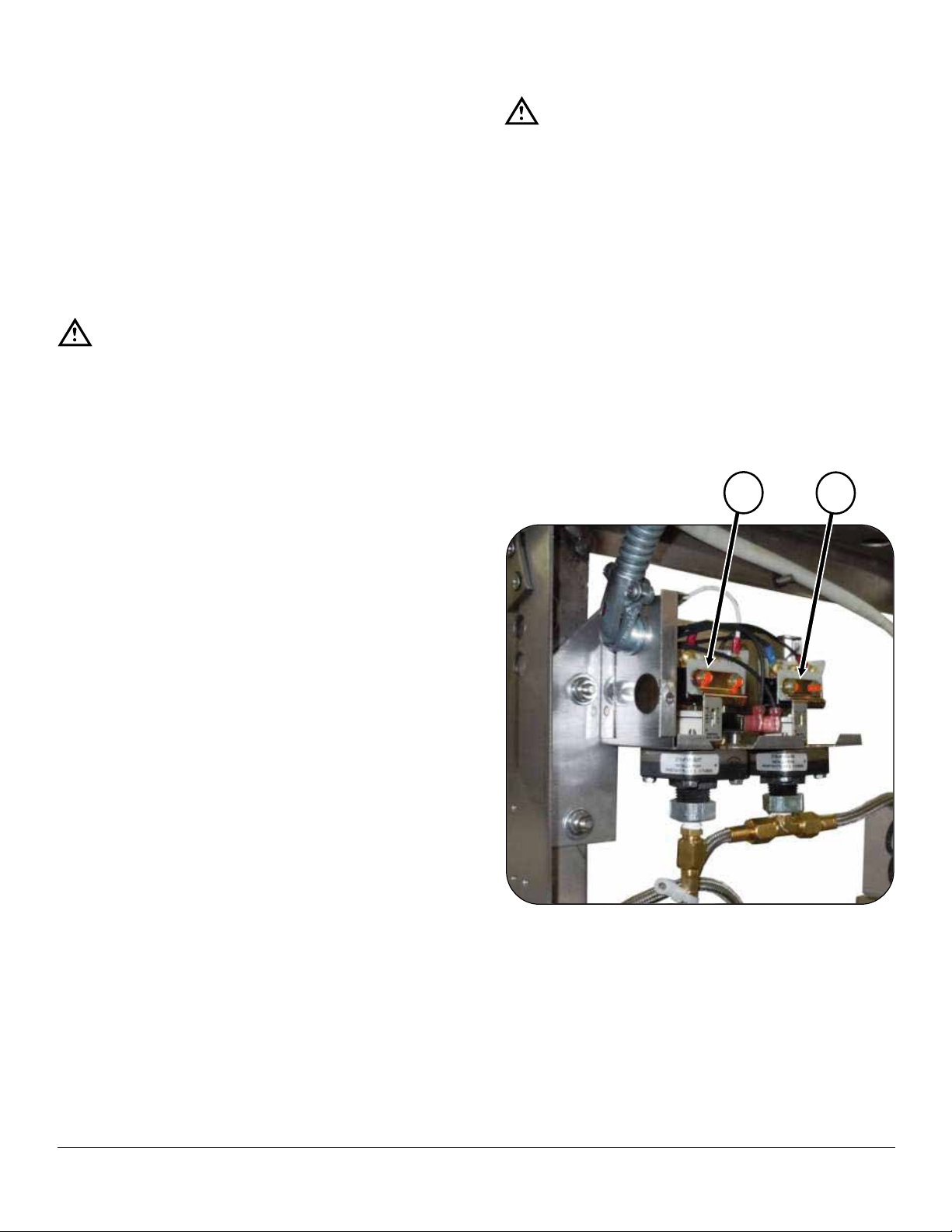
PRESSURE CONTROL SWITCH ADJUSTMENT
A
B
If boiler fails to maintain steam pressure in operating
range, pressure control switch may require adjustment.
1. Start boiler and allow pressure to build up to operating level - 15 PSI (1kg/cm²).
2. Check boiler pressure gauge. If gauge indicates 12
to 14 PSI, pressure control switches are properly adjusted.
3. If boiler does not come on when pressure gauge
reads 7 PSI and does not go off when pressure gauge
reads 14 PSI, proceed as follows:
WARNING
Because power must be on to adjust pressure
switches, be sure to protect against electrical
shock.
a. Remove screw and lift front cover off control box.
b. Hand adjust operating pressure control switch
and high limit pressure control switch by turning adjusting nut (Knurled knob) clockwise to
raise and counter clockwise to lower actuation
point. Switch should be set so that boiler comes
on when boiler pressure gauge reads 12 PSI
and goes off when gauge reads 14 PSI. Switch
should be set so that boiler will shut off if pressure reaches 15 PSI.
WARNING
Because power must be on to adjust pressure
switches, be sure to protect against electrical
shock.
1. Check that the (2) different switches are actually
used.
2. Set high limit switch H15 all the way to maximum at
15 PSI.
3. Set operating control switch F15 ON at 10 PSI, OFF
at 12 PSI.
When unit is properly operating, switch F15 will shut boiler off at approximately 14 PSI and turn back on at approximately 11 PSI.
Also, switch H15 will cause low water light on boiler control box (under cabinet) to come on due to reaching high
pressure.
c. The actuation value (differential) is factory set
and cannot be changed.
d. Repeat steps, 1, 2, and 3. If 45 to 14 PSI boiler
pressure gauge reading is obtained during boiler
operation, adjustment is correct. If proper adjustment cannot be made consult Trouble-Shooting
Guide in this manual.
e. After making adjustments, replace cover on pres-
sure switch box and screw.
OCTOBER 11, 2016 5 MT-25EO, MT-40EO & MT-60EO ELECTRIC KETTLES
Page 6
COLD WATER CONDENSER & LID COUNTERBALANCE ADJUSTMENT
COLD WATER CONDENSER ADJUSTMENT
The function of the cold water condenser is to keep
the temperature in the drain line from exceeding 150°F
(66°C). Solenoid valve (see Figure 4) controls the water
ow to the cold water condenser. The valve opens and
runs cold water through the drain until the temperature
drops below 150°F (66°C). The water ow may be regulated by adjusting thermostat dial.
The valve has a built-in water strainer which should be
removed and periodically cleaned.
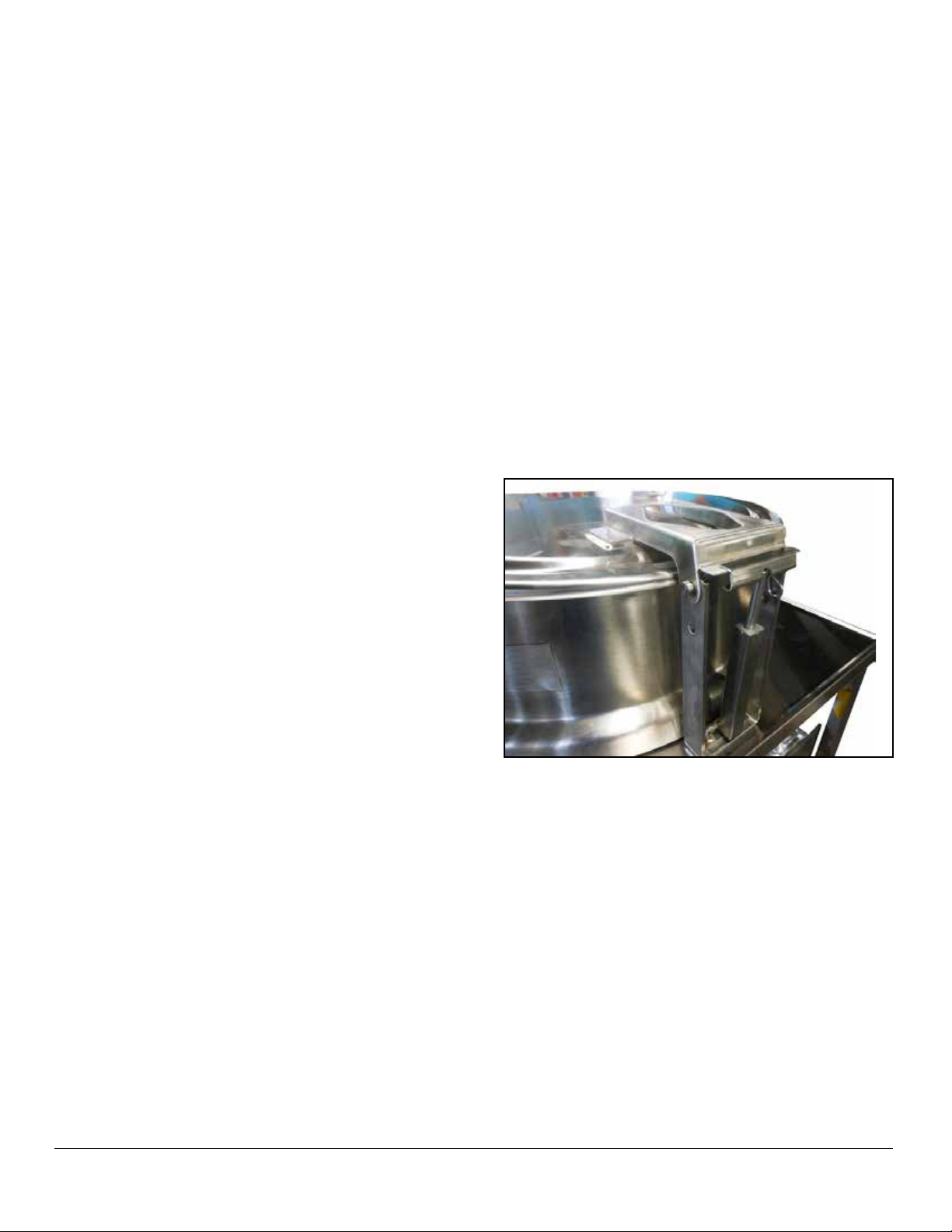
LID COUNTERBALANCE ADJUSTMENT
The kettle lid is equipped with a torsion spring counterbalance device to assist in lid lifting and to prevent slam-
ming. The device is shown assembled in gure 5 (internal
cabinet, side view) and exploded in gure 0 (hinge and lid
assembly). If lid slams closed when handle is released,
spring tension should be increased. If lid lifts up or refuses to remain down on kettle, tension should be reduced.
To adjust spring tension, proceed as follows:
1. Lift cover to open position.
2. Pull down on piston assembly to release it from its
position. Rotate “T” bar clockwise to increase tension,
continue clockwise to reduce tension.
3. Operate lid several times. Repeat step 2 until desired
operation is obtained.
4. Hold hex head screw rmly in position and tighten
hex nut to lock adjustment.
OCTOBER 11, 2016 6 MT-25EO, MT-40EO & MT-60EO ELECTRIC KETTLES
Page 7
HEATING ELEMENT REPLACEMENT
1
2 5 3
4
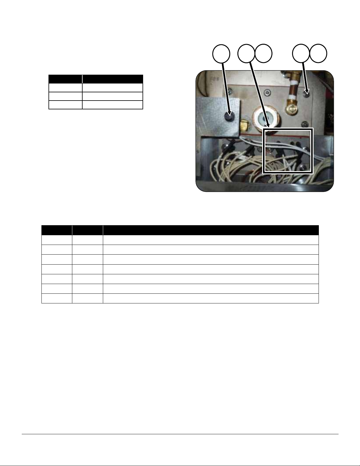
Check for defective heating elements as follows:
With the power off and disconnected, connect an ohmmeter to the two leads of each element loop at room
temperature. Resistance should be as follows:
VOLTS OHMS
208 10.8 +/- 5%
240 14.4 +/- 5%
*480 38.0 +/- 5%
*480 OHM rating Is based on 4000 w/277v.
If not, element is defective and must be replaced. Proceed as follows:
1. Shut down power to unit, boiler will drain.
2. Disconnect wires at contactor.
3. Remove nut (2) and gasket until element is freed.
4. Replace with new element.
ITEM PART NO. DESCRIPTION
1 08-6415 208V Element, 12 kW
1 08-6416 240V Element, 12 kW
1 08-6417 480V Element, 12 kW
2 91-8660 Element Gasket
3 98-3945 Nut
4 91-8756 Gasket Front Plate
5 08-6553 Secondary Low Water Cut Off
OCTOBER 11, 2016 7 MT-25EO, MT-40EO & MT-60EO ELECTRIC KETTLES
Page 8
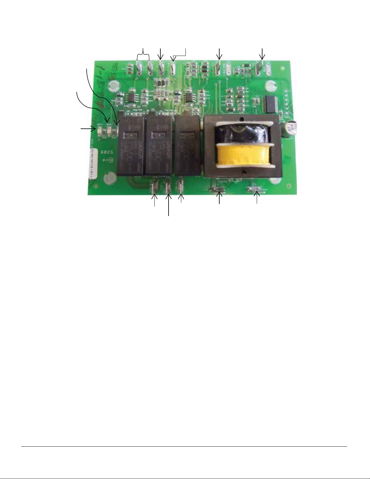
WATER CONTROL BOARD TESTING PROCEDURE
LED 1
LED 2
LED 3
RESET
LW2
GND
LW1
FW - HIGH
HTA NO
LO LITE (NC)
FW (NO)
L1
L2
This test procedure is to be used to determine if the control is working properly. It is not intended to determine why
the control may have failed.
If testing shows that the control is operating properly,
check all probe and solenoid wiring and the condition of
the electrodes in the steam chamber.
Contact the factory if the boiler still does not operate properly after completing the testing.
Tools Needed:
• Digital or Analog V-O-M meter.
• Alligator clip type test jumpers (2 sets min.).
Turn Off Power to Control:
• Use V-O-M to verify there is no power at terminals L
1 & L2.
• Use V-O-M to verify that there is no power at terminals ‘FW(NO)’, ‘LO LlTE(NC)’ & ‘HTR(NO)’. If there
is power at any of these terminals, you will need to
nd the source and turn it off.
Remove Wires from Probe and Relay Switch Terminals:
• DO NOT remove wires from L 1 & L2 terminals.
• Tag wires and remove from probe and relay contact
terminals including ‘GND’ terminal.
• Tag and remove wires from ‘RESET’ terminals.
• Connect jumper wire to both ’RESET’ terminals.
Turn Power On to Terminals L 1 & L2:
• ‘LED l’ should turn on.
• ‘LED 2’ should be off.
• ‘LED 3’ should be off.
• Use V-O-M to verify that there is power at ‘FW(NO)’
& ‘LO LlTE(NC)’ terminals and no power ‘HTR(NO)’
terminals
Test Feedwater Function:
• Connect jumper wire to ‘FW HIGH and ‘GND’ terminals.
• ‘LED l’ should turn off after a 10 second delay.
• Use V-O-M to verify that there is no power at the
‘FW (NO)’ terminal.
• Remove jumper from ‘FW HIGH’ and ‘GND’ terminals. . ‘LED l’ should turn on.
• Use V-O-M to verify that there is power at the
‘FW(NO)’ terminal.
OCTOBER 11, 2016 8 MT-25EO, MT-40EO & MT-60EO ELECTRIC KETTLES
Page 9

WATER CONTROL BOARD TESTING PROCEDURE
Test Primary Low Water Function:
• Connect jumper wire to ‘LW(1) and‘GND’ terminals.
• ‘LED 2’ should turn on.
• Remove jumper wire from ‘LW(1)’ and ‘GND’ terminals.
• ‘LED 2’ should turn off after a 3 second delay.
• Connect jumper wire to ‘LW(1)’ and ‘GND’ terminals.
• ‘LED 2’ should turn on.
IMPORTANT
Jumper wire between ‘LW(1) and ‘GND’ terminals must remain in place to test secondary
low water function.
Test Secondary Low Water Function:
• Connect jumper wire to ‘LW(2)’ and ‘GND’ terminals.
• ‘LED 3’ should remain off.
• Use V-O-M to verify that there is power at the ‘LO
LlTE(NC)’terminal and no power at the ‘HTR(NO)’
terminal.
• ‘LED 3’ should turn on.
• Use V-O-M to verify that there is no power at the
‘LO LlTE(NC)’ terminal and power at the ‘HTR(NO)’
terminal.
• Connect jumper wire to ‘RESET’ terminals.
• Remove jumper wire from ‘LW(2)’ and ‘GND’ terminals.
• ‘LED 3’ should turn off after a 3 second delay.
• USE V-O-M to verify that there is power at the ‘LO
LlTE(NC)’ terminal and no power at the ‘HTR(NO)’
terminal.
• Connect jumper wire from ‘LW(2)’ and ‘GND’ terminals.
• ‘LED 3’ should remain off.
IF ANY OF THE FUNCTIONS DO NOT WORK, REPLACE THE BOARD!
IF ALL FUNCTIONS WORK, TROUBLE-SHOOTING
OTHER COMPONENTS WILL BE REQUIRED!
• Remove the jumper wires from the ‘RESET’ terminals.
OCTOBER 11, 2016 9 MT-25EO, MT-40EO & MT-60EO ELECTRIC KETTLES
Page 10

WATER LEVEL CONTROL ADJUSTMENT
Circuit Operation
Boiler water level is controlled by rising and falling water
level which makes and breaks circuits between two different length probe electrodes inside boiler and the grounded boiler wall.
The short probe is used to turn water on and off as required. The long probe is used to cut off power to the
heating elements and give a signal alarm when water is
too low.
A secondary low water cut-off is used as a warning device
to dry ring and serves as a warning device to delime/
descale boiler.
Water Level Control Operation
Starting with an empty boiler, switch S1 is closed to start
the following sequence.
1. Solenoid R-1 energizes allowing water to ow into
boiler. At the same time, the primary circuit of T-1 is
energized.
2. Boiler continues to ll until water level reaches tip of
electrode probe A completing the secondary circuit of
T-1 and energizing C-3.
3. When C-3 is energized, NC (normally closed) contact
opens which de-energizes R-1 and stops water ow.
NO (normally open) contact closes completing circuit
to probe B.
As water boils away below the end of probe B, the following occurs:
1. Secondary circuit of T -1 is broken and C-3 de-energizes.
Water Level Control Maintenance & Cleaning
The water level is controlled by two probes mounted on
the top of the boiler or on front of the boiler. Inspection
should be done at least two times a year as determined
by local water conditions. Probe electrodes must be as
free of scale and sludge build-up as possible to insure
proper functioning of water level control system.
Electrode lengths must be checked to insure proper water
level settings.
If probe electrodes and housing appear to have little or
no build-up of scale or sludge, use Market Forge Total
Concept Chemical Cleaner Descaler (p/n 20-0307) for
this minor cleaning. This type of cleaning should be done
at least twice a year (refer to page 25 for complete Total
Concept Application Instructions)
Probe Cleaning
The following procedure should be followed for cleaning
probes when build-up is considerable (at least once a
year):
1. Clean both probes, in detergent and water using a nylon brush for scrubbing. Rinse thoroughly in clear water. If scale and sludge build-up has been removed,
and reinstall. If probes are not clean, proceed to step
#2 and #3.
2. Use emery cloth or sandpaper to remove scale from
probes. Rinse thoroughly in clear water.
3. A U.S.D.A. approved boiler cleaner may be used for
more thorough cleaning of probes.
2. When C-3 de-energizes, NO contact opens to break
circuit to probe A while NC contact closes which en-
ergizes R-1 and allows boiler to ll.
Low Water Cut-Off
When S-1 is closed, the following also occurs:
1. Primary circuit of T -2 is energized.
2. When water level reaches probe C and S-2 is momentarily closed, C-4 is energized.
3. When C-4 is energized, NO contacts close completing low water cut-off circuit through contacts 7 and 8
and completing circuit through contacts 3 and 4 energizing C-1 and C-2 which closes heater circuit.
If water drops below probe C, the following occurs:
1. Secondary circuit of T-2 breaks and C-4 de-energizes. Contact 7 and 8 and 3 and 4 open to break circuit
to C-1 which opens circuit to heating elements.
C-1 and C-2 will not operate until water level in boiler
is normal and S-2 is momentarily closed.
OCTOBER 11, 2016 10 MT-25EO, MT-40EO & MT-60EO ELECTRIC KETTLES
Page 11

DRAW-OFF VALVE REPAIR
Common Leak Repairs
To repair a valve leak, the source must rst be determined. Leaks from around the valve steam are corrected
by replacing the rubber "0" ring. Dripping from the valve
outlet which occurs with the valve tightly closed indicates
faulty seating of the valve disc (pan of 6) against the valve
seat. Dripping is often corrected by cleaning residue from
disc and seat using very ne emery.
Valve Seat Lapping
If either the disc (pan of 6) or seat is found damaged, it is
necessary to either replace the entire valve or perform the
lapping procedure as follows:
1. Disassemble valve and clean both disc and valve
seat.
2. Attach handle (2) to stem with valve bonnet (4) removed.
3. Apply a good grade of ne lapping compound to disc
and inset it into valve to make light contact against
seat.
4. Rotate stem disc against seat by turning handle. This
rotation allows stem to wobble in space the bonnet
would normally occupy. Continue with light pressure
until compound dries.
5. Reassemble and test for leaks with valve closed. If
dripping occurs, repeat lapping procedure as many
times as required to obtain a water-tight seal.
OCTOBER 11, 2016 11 MT-25EO, MT-40EO & MT-60EO ELECTRIC KETTLES
Page 12

TILTING MECHANISM REPAIR
MT40EO tilting kettles are equipped with tilting mechanisms.
Lift Screw Assembly Removal
The assembly is removed with the kettle in the lowered
position. Assembly removal proceeds as follows:
1. Remove the two bolts which hold ball nut assembly in
screw lever (7).
2. Remove the two 5/16" hex head cap screws which
fasten the screw housing to cabinet frame.
3. Lift screw assembly from cabinet.
NOTE: Proceedin reverse order to replacethe assem-
bly.
General Inspection & Cleaning
The screw assembly should run smoothly throughout
the entire stroke. If operation is not uniform, remove the
screw assembly (see Saginaw screw assembly removal)
and proceed as follows:
1. Inspect screw shaft for accumulation of foreign matter
in the ball grooves.
2. Using cleaning uid or solvent, remove dirt from ball
grooves. Be sure to ush the ball nut assembly thoroughly.
Lift Screw / Tilting Mechanism
The driving end of the Lift Screw is formed into a slotted
sleeve which receives the engagement pins of the removable hand crank.
The Lift Screw assembly must be removed from the kettle
to complete installation. The collar is removed by driving
out the roll pin which secures it to the screw shaft. The
replacement sleeve slides over the faulty shaft end and
is fastened with a roll pin. The repair is completed by remounting the Saginaw Screw assembly.
Tilting Mechanism Lubrication
Lubrication of the tilting mechanism is the only required
preventive maintenance other than daily cleaning. Inspect the screw of the tilting mechanism annually for
adequate lubrication. If screw appears "dry", apply good
grade bearing grease directly on the threads so that the
threads appear to be barely damp. If mechanism fails to
run smoothly.
3. Cycle the ball nut along the screw shaft several times.
Then, wipe with a dry, lint less cloth and lubricate immediately.
OCTOBER 11, 2016 12 MT-25EO, MT-40EO & MT-60EO ELECTRIC KETTLES
Page 13

WIRING DIAGRAM
OCTOBER 11, 2016 13 MT-25EO, MT-40EO & MT-60EO ELECTRIC KETTLES
Page 14

SCHEMATIC
OCTOBER 11, 2016 14 MT-25EO, MT-40EO & MT-60EO ELECTRIC KETTLES
Page 15

PRESSURE SWITCHES
2
1
3
FRONT AND REAR VIEW
ITEM PART NO. DESCRIPTION
1 10-8410 HIGH LIMIT – PRESSURE SWITCH
2 10-8411 OPERATING – PRESSURE SWITCH
3 98-4131 STAINLESS STEEL, BRAID HOSE, 5/16 ID X 22” LONG
OCTOBER 11, 2016 15 MT-25EO, MT-40EO & MT-60EO ELECTRIC KETTLES
Page 16

DRAIN ASSEMBLY
3
6
4
2
5
1
ITEM PART NO. DESCRIPTION
1 10-4804 PRESSURE GAUGE
2 10-7974 SIGHT WINDOW
3 10-0412 SWING DRAIN
4 90-7475 SUPPORT, NIPPLE, DRAIN
5 08-6553 LOW WATER CUT OFF
6 91-1835 STRAINER
OCTOBER 11, 2016 16 MT-25EO, MT-40EO & MT-60EO ELECTRIC KETTLES
Page 17

TILTING MECHANISM
7
7
3
5
2
4
6
1
8
9
10
12
11
13
Manual Tilt
Power Tilt
ITEM PART NO. DESCRIPTION
1 91-9335 POWER TILT MOTOR WELD ASSEMBLY
2 91-9336 MOTOR MOUNTING PLATE
3 98-1726 POWER LIFT FOOT BRACKET
4 91-9353 POWER TILT NYLON STRIP
5 98-0555 LIFTING LEVER ARM
6 91-9387 LEVER ARM
7 91-9324 LIFT SCREW ASSEMBLY
8 98-4131 CONDENSER HOSE
9 90-3490 HINGE BLOCK
10 08-5217 VALVE RETAINER COLLAR
11 10-5242 VALVE
12 98-4128 FAUCET HOSE
13 98-3696 MOTOR
OCTOBER 11, 2016 17 MT-25EO, MT-40EO & MT-60EO ELECTRIC KETTLES
Page 18

PISTON ASSEMBLY
9
ITEM PART NO. DESCRIPTION
1 98-0530 Housing-Compression Rod & Spring
2 98-0535 Compression Rod
3 08-4606 Compression Spring
4 98-0537 Floating Nut
5 98-0536 End Guide
6 08-4200 Rivet, Barbed
7 08-3205 Hooking Pin, Driv Lok Type “E” 7/32 x 2
8 08-1208 Plug, Plastic
9 98-0529 COMPLETE PISTON ASSEMBLY
OCTOBER 11, 2016 18 MT-25EO, MT-40EO & MT-60EO ELECTRIC KETTLES
Page 19

VALVE AND FAUCET
1
4 2 3
7
6
5
8
10
9
11
ITEM PART NO. DESCRIPTION
1 10-0105A KNOB
2 10-6303 VALVE RETAINER COLLAR
3 10-5242 VALVE
4 90-3490 HINGE BLOCK
5 91-4795 RUBBER HOSE, 3/4” ID X 36” LONG
6 90-3210 MAGNETIC BRACKET
7 10-5561 DOOR MAGNET
8 10-5753 NOZZLE, SWIVEL SPOUT
9 91-0887 RISER, 15” LONG
10 10-7680 FAUCET SET
11 08-5467 ADAPTER
OCTOBER 11, 2016 19 MT-25EO, MT-40EO & MT-60EO ELECTRIC KETTLES
Page 20

LOW WATER CUTOFF
2 3 1
4
1
ITEM PART NO. DESCRIPTION
1 08-6553 LOW WATER CUT OFF
2 08-0034 ANODE ROD
3 08-4900 BALL VALVE, 1/4”
4 10-7974 SIGHT WINDOW
OCTOBER 11, 2016 20 MT-25EO, MT-40EO & MT-60EO ELECTRIC KETTLES
Page 21

CRANK SHAFT
ITEM PART NO. DESCRIPTION
1 08-7906 Handle with Knob
2 08-7911 Screw, Set 1/4 – 20, 3/8” Long
3 98-1537 Assembly, Crank Shaft
4 90-8878 Clip, Bracket, Universal
5 10-1735 Screw, #8-32, Sheet Metal
6 10-2508 Washer, Stainless Steel
OCTOBER 11, 2016 21 MT-25EO, MT-40EO & MT-60EO ELECTRIC KETTLES
Page 22

BOILER BASE ASSEMBLY
1
9
3
5
6
4
8
11
10
2
7
12
ITEM PART NO. DESCRIPTION
1 09-4815 AIR VENT
2 10-4653 CONDENSER THERMOSTAT
3 10-5320 PRESSURE RELIEF VALVE
4 08-4900 1/4” BALL VALVE
5 08-6338 LOW WATER PROBE
6 08-6337 HIGH WATER PROBE
7 10-1311 DRAIN VALVE
8 10-3661 STEAM RADIATOR VALVE
9 08-4874 VACUUM BREAKER VALVE
10 90-1873 DRAIN ASSEMBLY, TEE & BRACKET
11 90-7475 DRAIN SUPPORT, NIPPLE
12 14-0535 BOILER TANK
OCTOBER 11, 2016 22 MT-25EO, MT-40EO & MT-60EO ELECTRIC KETTLES
Page 23

ELECTRICAL COMPONENTS
2
1
3
4
5
7
8
6
ITEM PART NO. DESCRIPTION
1 10-4653 THERMOSTAT
2 08-6472 RELAY
3 08-6475 RELAY SOCKET
4 08-7926 TERMINAL STRIP, TB1
5 98-1680 LIQUID LEVEL CONTROL BOARD, 120V
6 10-5944 CONTACTOR, 40 AMP
7 10-5070 TERMINAL BLOCK, END SECTION
7 10-5503 TERNIMAL BLOCK, CONTACT SECTION
8 97-4616 TERMINAL BLOCK ASSEMBLY, 3 CONTACT
-- 10-6859 MICRO SWITCHES (FOR POWER LIFT)
-- 08-8017 CAPACITOR, 370 VAC, 50/60 HZ, 7.5 MFD (OPTIONAL)
OCTOBER 11, 2016 23 MT-25EO, MT-40EO & MT-60EO ELECTRIC KETTLES
Page 24

VALVE ASSEMBLY
2
1
4
5
3
ITEM PART NO. DESCRIPTION
1 08-4822 WATER VALVE
2 08-4979 CHECK VALVE
3 98-4131 CONDENSER HOSE
4 98-4130 FILL HOSE
5 98-4128 FAUCET HOSE
OCTOBER 11, 2016 24 MT-25EO, MT-40EO & MT-60EO ELECTRIC KETTLES
Page 25

KETTLE JACKET ASSEMBLY
1
2
3
5
4
ITEM PART NO. DESCRIPTION
1 10-5319 STEAM TRAP
2 90-7493 RUBBER HOSE, 3/8 ID X 40” LONG
3 90-7495 RUBBER HOSE, 3/4 ID X 36” LONG
4 10-7680 FAUCET SET
5 98-0771 LIFT ARM, FOR 40 GALLON KETTLE
5 98-0599 LIFT ARM, FOR 25 & 60 GALLON KETTLE
OCTOBER 11, 2016 25 MT-25EO, MT-40EO & MT-60EO ELECTRIC KETTLES
 Loading...