

Page 1
SERVICE & PARTS MANUAL
Steam
-
Jacketed, Electric
Models:
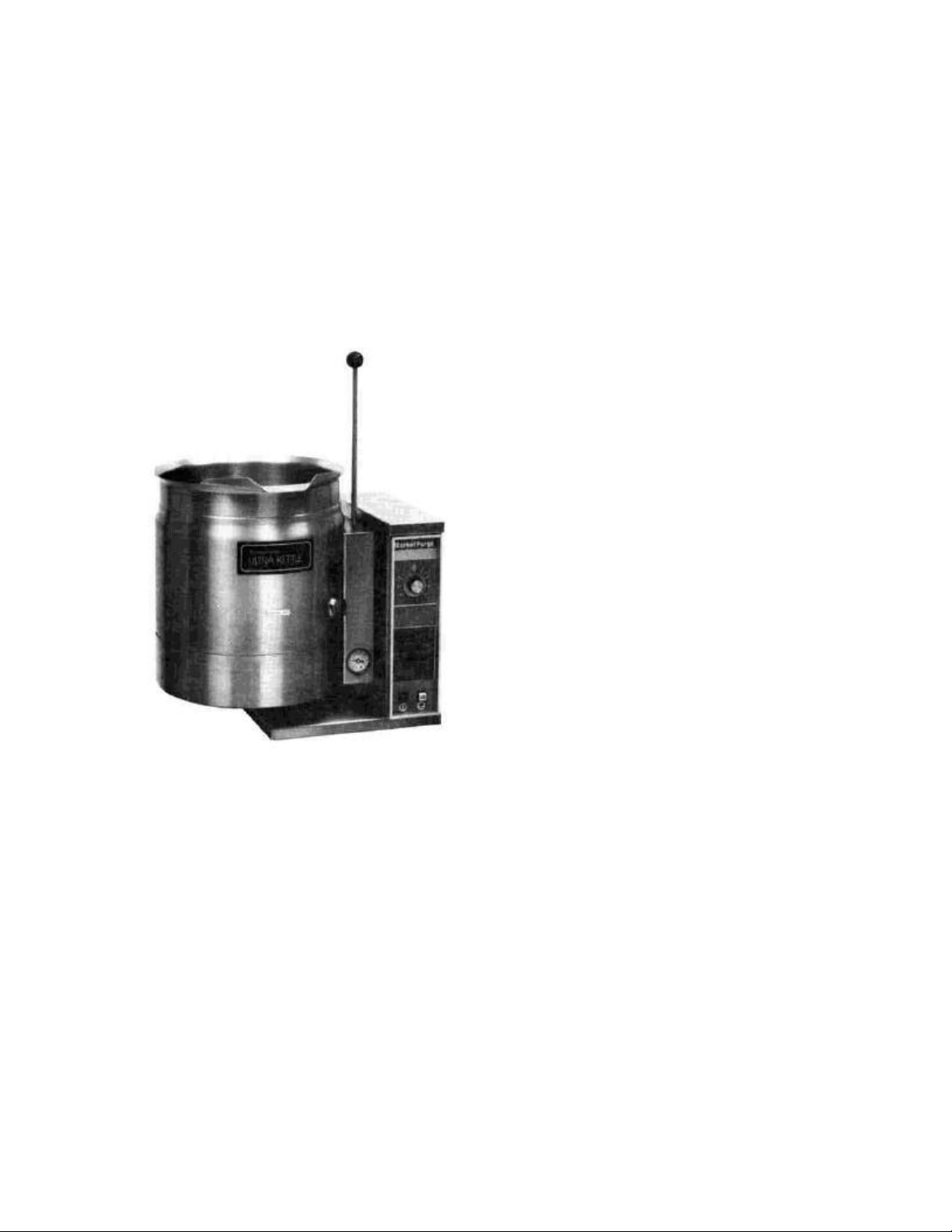
ULTRA KETTLES®
Self-contained Counter-Top,
MFT6CE
MFT10CE
Form No. S-2287 8/83 Printed in U.S.A.
Market Forge Co.
35 Garvey St., Everett, MA. 02149
Tel. (617) 387-4100, Telex 94-9414, Cable MAFORCO
Page 2

TABLE OF CONTENTS
Paragraph Page
Paragraph Page
SECTION 1 INTRODUCTION
1.1 Description ..............……………….... 1-1
1.2 Basic Functioning ...........………….... 1-1
1.3 Service .....................………………... 1-1
SECTION 2 OPERATION
2.1 Operating Controls and Indicators. .. 2-1
2.2 Operating Procedures ........………... 2-1
2.3 Reservoir Fill Procedure ...………..... 2-1
2.4 Automatic Venting............…….…….. 2-1
2.5 Kettle Washing ................. …………..2-3
LIST OF ILLUSTRATIONS
Figure Page
SECTION 2 OPERATION
2-1 Controls and Indicators. ....…………….... 2-2
2-2 Temp. and Pressure Control Settings . . . 2-3
SECTION 3 MAINTENANCE
3-1 Wiring Label #A09-5932. .....……………. 3-3
3-2 Wiring Label #A09-5933. ...……………... 3-4
3-3 Wiring Label #A09-5934. ...……………... 3-5
3-4 Schematic Diagram ...........……………... 3-6
3-5 Access Panel To Heating Element …….. 3-10
SECTION 3 MAINTENANCE
3.1 General .....................……………………...3-1
3.2 Trouble-Shooting Guide ...…………….... 3-1
3.2.1 Electrical Fault Isolation ..……………...... 3-2
3.2.2 Water Level Control. .........………… ….. 3-6
3.2.2.1 Circuit Operation .........……………..... 3-6
3.2.2.2 Control Fault Isolation. ...…………..... 3-6
3.3 Repair and Replacement. ....………... 3-6
3.3.1 Console Control Components. ..……….. 3-6
3.3.2 Temperature and Low Water Probes. …. 3-7
3.3.3 Heating Element ...........………………... 3-7
SECTION 4 ILLUSTRATED PARTS LIST
4.1 General ....................……………………….. 4-1
4.2 Ordering Information....…………………...... 4-1
Figure Page
SECTION 4 ILLUSTRATED PARTS LIST
4-1 Kettle Exterior Controls and Indicators….. 4-2
4-2 Kettle Bottom View..........………………….. 4-4
4-3 Control Bracket Assembly. .……………...... 4-6
4-4 Control Box - Top View. ....……………….... 4-8
4-5 Control Box -
Rear View and Bottom View …………... 4-10
LIST OF TABLES
Table Page
SECTION 2 OPERATION
2-1 Controls and Indicators. ......……….... 2-2
2-2 Temperature Control Setting Guide ... 2-4
Table Page
SECTION 3 MAINTENANCE
3-1 General Trouble-Shooting Guide . . . 3-1
3-2 Electrical Ratings .............…………... 3-7
ii S-2287
Page 3

SECTION I INTRODUCTION
THIS SERVICE AND PARTS MANUAL CONTAINS DESCRIPTIVE INFORMATION, OPERATING INSTRUCTIONS, AND
MAINTENANCE AND TROUBLE -SHOOTING INFORMATION FOR MODELS MFT6CE AND MFT10CE STEAM-JACKETED
ULTRA KETTLES® PARTS LISTS ARE ALSO INCLUDED IN WHICH EACH REPLACEABLE PART IS IDENTIFIED AND
SHOWN IN AN ACCOMPANYING ILLUSTRATION.
1.1 DESCRIPTION
Market Forge Models MFT6CE (6 gallon capacity)
and MFT1 OCE (10 gallon capacity) are selfcontained, counter-top, tilting Ultra Kettles® Each
model has a jacket of double-wall construction
forming a sealed reservoir around the lower two-thirds
of the kettle. The reservoir is charged with water and
anti-freeze solution. Kettles are equipped with a
removable electric heating element and controls,
including a low water cutoff device for protection of
the heating element. Both models are of identical
construction, except for kettle size and element
heating capacity.
1.2 BASIC FUNCTIONING
Self-contained kettles operate by generating steam
in the kettle reservoir. The sequence of operation is
as follows:
1. Operator presses the power switch to the ON
position and sets the temperature control dial at
the desired setting from 1 to 10 (100°F to 300°F,
38°C to 149°C, jacket temperature).
2. Control circuit is normally completed to the temp-
erature controller if the following conditions exist:
a. Water level in kettle reservoir is adequate to
prevent circuit interruption by the low water cutoff
device. An activated cutoff is indicated by the
buzzer sounding, amber low water light turning on,
and the heating element shutting off.
b. Kettle is in vertical position with circuit completed through the tilt interlock switch (Micro
switch).
3. Thermostatic control contacts close to energize
contactor coils.
4. Power is supplied to the elements through closed
power contactors.
5. As the temperature of water rises in the kettle
reservoir, increase in steam pressure is indicated
on the pressure gauge. Models after 1982 have the
automatic venting feature (Vent -Rite Air Valve).
6. When the temperature of steam in the reservoir
reaches the setting shown on the temperature
control dial, the temperature controller opens to
break the contacts and shut off the heating
element. On/off cycles will occur as required to
maintain temperature control.
1.3 SERVICE
Required service, both preventive and corrective, is
explained in Section 3. Should repairs be required, a
network of authorized agencies is available to assist
with prompt service. A current Directory of Authorized
Service Agencies may be obtained by contacting:
Product Service Department
MARKET FORGE CO.
35 Garvey Street
Everett, Massachusetts 02149
Telephone: (617) 387-4100
The model and serial numbers must be referenced
when corresponding with Market Forge. These
numbers can be found on the data plate located on
the back of the control box.
1-1 S-2287
Page 4
SECTION 2 OPERATION
TABLE
2-1
TEMPERATURE CONTROL SETTING
2.1 OPERATING PROCEDURES
Instructions for operating the self -contained kettles are as
follows:
1. Check that the external electrical shut -off to the kettle
(such as a main circuit breaker) is on.
2. Push power switch to ON position; switch will glow red in
ON position.
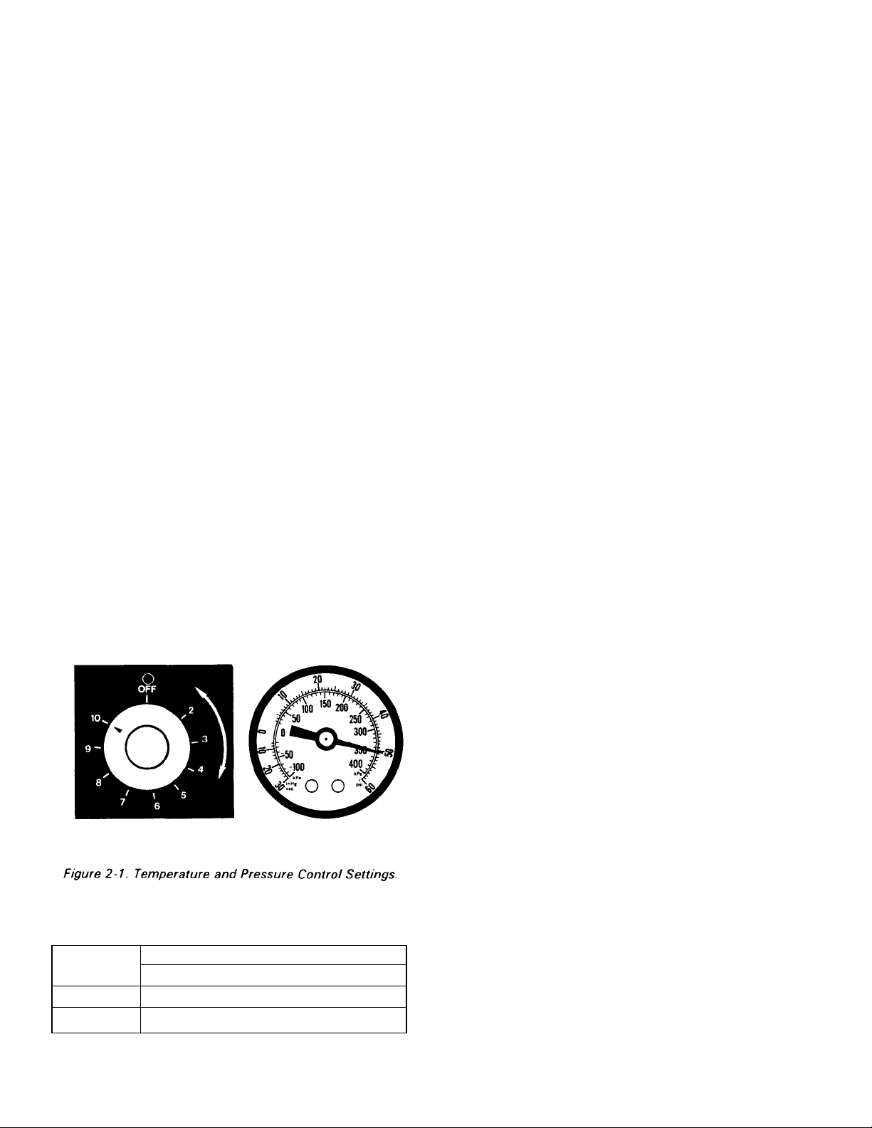
3. To preheat kettle, set temperature control dial at 10, and
wait until pressure gauge reads 50 psi. (Do not preheat
when cooking milk and products which cook onto hot
cooking surfaces. These foods should be put into the
kettle before heating.) Figure 2-1 shows the correct
settings for the temperature control dial and the pressure
gauge.
4. Put food to be cooked into kettle.
5. Set temperature control dial at the required setting from 1
to 10 coinciding with a temperature range from roughly
100°F to 300°F, 38°Cto 149°C, in the jacket. Table 2-1
Temperature Control Setting Guide, shows the
relationship between the temp erature control setting and
the water temperature.
6. When finished cooking, set temperature control knob to
OFF, and push the power switch to OFF.
7. Pour finished product from kettle using tilt handle, being
careful to avoid splashing.
8. Wash kettle thoroughly. See subsection 2.5 for
instructions.
2.2 OPERATING CONTROLS AND INDICATORS
The controls and indicators used to operate the MFT6CE
and MFT10CE tilting Ultra Kettles® are discussed in this
section. Figure 2-2 shows the physical location of the controls
and indicators. Table 2 -2 lists each control and indicator and
its function.
2.3 RESERVOIR FILL PROCEDURE
The reservoir water level must be maintained at or above
the minimum needed to submerge the heating element. If the
amber low water light turns on and the buzzer sounds during
use, the water level is not adequate and the low water
protection control has automatically shut off the heating
element. Low water light will stay lit and buzzer will sound until
the jacket reservoir has again been filled to a safe water level.
WARNING: Before connecting water to this unit,
water supply should be analyzed to make sure
hardness is no greater than 2.0 grains per gallon
and pH level is within the range of 7.0 - 7.5 Water
which fails to meet these standards should be
treated by installation of a water conditioner.
EQUIPMENT FAILURE CAUSED BY INADEQUATE WATER QUALITY IS NOT COVERED
UNDER WARRANTY.
Fill Procedure
The following procedure must be completed before further use.
CAUTION: THERE SHOULD BE NO PRESSURE IN THE
KETTLE DURING THE FILL PROCEDURE.
TO FILL:
1. Push in low water switch.
2. Turn elbow on safety valve upright.
3. Pull lever on safety valve up and add water through elbow
until low water light goes out and buzzer stops. CAUTION:
Be sure to turn elbow to down position to avoid injury from
escaping steam.
4. Push low water switch to reset.
NOTE
If the kettle is to be subjected to temperatures below 32°F,
0°C, it is essential that either the proper proportion of 1 part
(104 oz.) anti-freeze to 3 parts (31 2 oz.) water be
maintained in the kettle jacket, or that the jacket be
emptied.
Temp. °F
Temp. °C
1 2 3 4 5 6 7 8 9 10
GUIDE
Control Number
90 125 160 195 231 273 300
32 52 71 91 110 134 149
2-1 S-2287
2.4 AUTOMATIC VENTING
If there is any air in the kettle jacket after filling, it will be
relieved by the Automatic Venting system.
Page 5
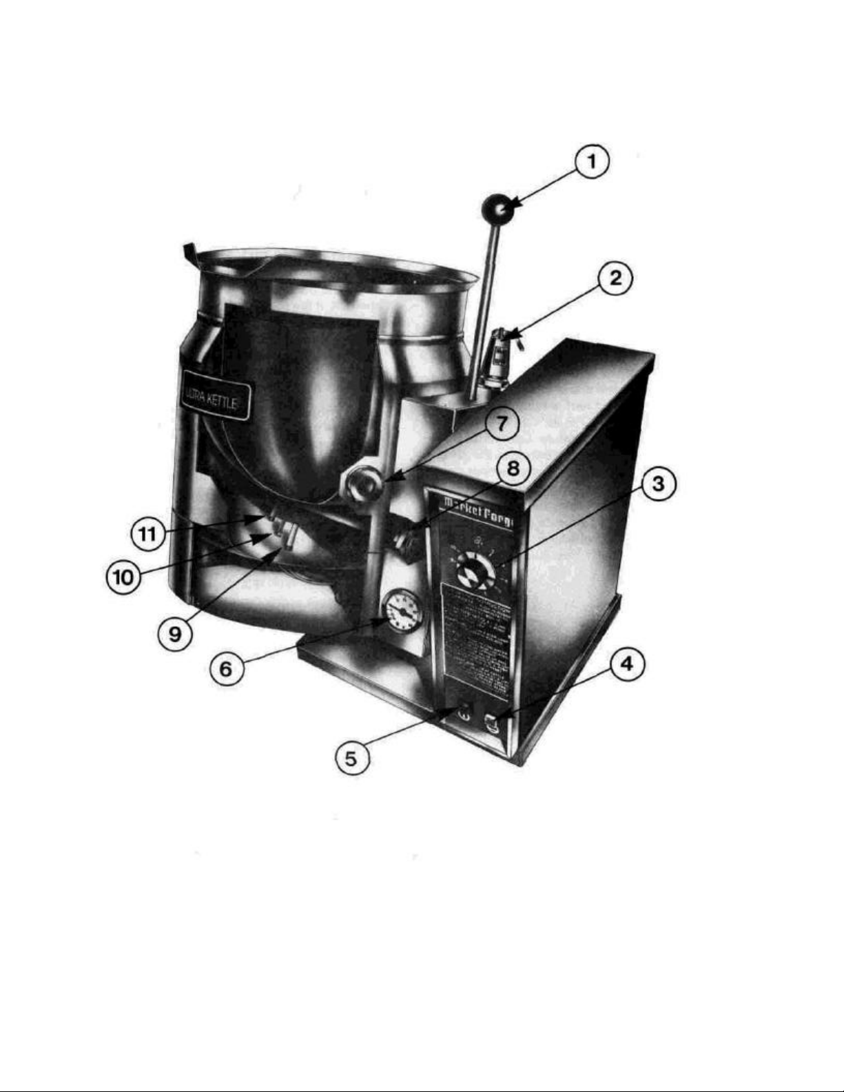
Figure 2-2. Controls and Indicators.
Page 6
TABLE 2-2
CONTROLS AND INDICATORS
2-3
Figure 2.2
Ref. No. Description Function
1 Tilt Handle Used to move kettle to upright or downward position for ease in
pouring and washing.
2 Safety Relief Valve Safety relief va lve opens automatically to release excessive steam
pressure in kettle reservoir. (Located on rear of kettle.)
3 Temperature Control
Knob
Allows operator selection of kettle temperature in increments from 1
to 10, 100°F to 300°F, 38°C to 149°C steam jacket temperature and
OFF.
4 Low Water Switch Glowing amber light indicates that the low water protective device
has cut off power supply to controls and heating element.
5 Power ON/OFF Switch Controls power to kettle.
6 Pressure Gauge Indicates pressure in pounds per square inch (PSI) inside kettle.
7 Water Level Sight
Sight glass shows water level in kettle reservoir.
Window
8 Heating Element Heats water to desired temperature.
9 & 11 Fittings , Electrode
(Water Probes)
Low water probe in conjunction with the low water cutoff protects the
kettle from a low water condition.
10 Temperature Sensor Measures water temperature.
Not Shown Vacuum Breaker Breaks hazardous vacuum. (Located on rear of kettle.)
Not Shown Vent-Rite Air Valve Automatically vents air from kettle. (Located on rear of kettle.)
2.5 KETTLE WASHING
The kettle interior and exterior should be thoroughly
washed after each use. The kettle can be moved from
an upright to a downward position by pulling the tilt
knob forward and pushing the tilt handle downward. To
move the kettle to the upright position, simply reverse
the procedure. To wash the kettle follow the directions
below:
1. Fill kettle with water immediately after each use to
facilitate cleaning even if kettle is not going to be
washed at that time.
2. Prepare a warm water and mild detergent solution
in the kettle.
3. Remove food soil using a nylon brush. CAUTION:
Do not scrape inside of the kettle with metal tools
steel scouring pads, or abrasive cleaners.
Scratches will result which ruin the general
appearance of the kettle, make it harder to clean
and maintain in sanitary condition.
4. To loosen food which is stuck to the kettle, allow
it to soak at a low temperature setting.
5. Rinse with clear water and dry interior of ket tle.
6. Wipe down exterior of kettle, rinse, and dry.
CAUTION: Never get water into the electrical
controls.
S-2287
Page 7

SECTION 3 MAINTENANCE
PROBLEM
CONTROLLER SET.
b. Kettle tilted.
Retur
n kettle to full vertical position.
c. Low water level in kettle reservoir.
Fill reservoir (
see subsection 2.3
).
g. Faulty interlock switch (Micro switch).
Replace interlock switch.
c. Burned out heating elements.
See
s
ubsection 3.3.3
.
d. Faulty contactor.
Replace contactor.
b. Defective low water controller.
Replace control (
see subsection 3.2.2
).
5.
KETTLE HARD TO TILT.
3.1 GENERAL
This section contains trouble-shooting and main-
tenance information intended for use by authorized
personnel. It is recommended that the operator never
attempt to make repairs without such assistance. A
current Directory of Authorized Service Agencies may
be obtained from Market Forge (see subsection 1.3).
3.2 TROUBLE-SHOOTING GUIDE
Table 3-1 gives information to assist service per-
sonnel in locating the general source of problems
which may occur with the self-contained kettles.
Before attempting to locate the source of difficulty, the
technician should be familiar with the operating
instructions in Section 2 and the basic functioning
described in subsection 1.2.
TABLE 3-1 GENERAL TROUBLE-
SHOOTING GUIDE
Probable Cause Remedy
1. POWER ON/OFF SWITCH FAILS TO LIGHT WITH SWITCH IN ON POSITION AND TEMPERATURE
a. Power to kettle off. Locate external shut -off (circuit breaker) for
incoming power and place in ON position.
d. Power ON/OFF light burned out. Replace light.
e. Faulty power ON/OFF switch. Replace switch.
f. Faulty temperature controller. Replace temperature controller.
h. Faulty water level control. Replace control (see subsection 3.2.2).
i. Faulty wiring. Inspect condition of wire and tightness of all
connectors. Correct as required.
2. KETTLE NOT HOT ENOUGH TO BOIL WATER WITH TEMPERATURE CONTROLLER SET AT 10
a. Air in kettle reservoir Replace Vent -Rite valve.
b. Faulty weeping safety relief valve. Replace valve.
e. Faulty temperature controller. Replace temperature controller.
3. SAFETY RELIEF VALVE WEEPS OR OPENS REPEATEDLY.
a. Before reaching 55 psi. Change valve.
b. Faulty safety relief valve. Replace valve.
4. LOW WATER LIGHT ON.
a. Low water level in reservoir. Fill reservoir (see subsection 2.3).
c. Defective low water probe. Replace probe (see subsection 3.3.2).
d. Faulty wiring. Inspect and repair as required.
a. Bearings loose or lacking lubrication. Repair or replace as required.
3-1 S-2287
Page 8

3-2
3.2.1 Electrical Fault Isolation
Correction of an electrical failure first requires isolation of
the fault to a single circuit or component. In most cases, the
nature of the failure and its effect upon the operation of the
kettle will be sufficient to
isolate it to one or more circuit elements. The General
Trouble-Shooting Guide (Table 3-1), 3 Wiring Diagrams
(Figures 3-1, 3-2, and 3-3), and the Schematic Diagram
(Figure 3-4) are provided as guides for isolation of electrical
faults.
Figure 3-1. Wiring Label #A09-5932.
S-2287
Page 9

3-3
Figure 3-2. Wiring Label #A09-5933.
S-2287
Page 10

3-4
S-2287
Figure 3-3. Wiring Label #A09-5934.
Page 11

Figure 3-4. Schematic Diagram.
S-2287
Page 12

3-6
The electrical ratings are shown in Table 3-2, below:
ELECTRICAL RATINGS
KETTLE SZ KW VOLTS AMPS PHASE ELEMENT PT #
6 GALLON 8 208 39 1 09-6500
6 GALLON 8 208 23 3 09-6494
6 GALLON 8 240 34 1 09-6501
6 GALLON 8 240 20 3 09-6487
6 GALLO N 8 480 17 1 09-6502
6 GALLON 8 480 10 3 09-6488
6 GALLON 8 380 13 3 09-6584
6 GALLON 8 415 12 3 09-6586
10 GALLON 12 208 58 I 09-6503
10 GALLON 12 208 34 3 09-6495
10 GALLON 12 240 50 1 09-6504
10 GALLON 12 240 29 3 09-6489
10 GALLON 12 480 25 1 09-6505
10 GALLON 12 480 15 3 09-6490
10 GALLON 12 380 19 3 09-6585
10 GALLON 12 415 17 3 09-6587
3.2.2 Water Level Control
3.2.2.1 Circuit Operation
The low water circuit includes a low water controller,
water level probe, and low water light. The water level
controller provides circuit cutoff to the heating element. The
amber low water light will go on and the buzzer will sound
when the reservoir water level is not in contact with the
probe.
Detailed wiring labels, including internal control wiring,
are shown in Figures 3-1, 3-2, and 3-3. In normal operation,
with adequate water level, the relay coil circuit is completed
between the ground and water contacting the probe. The
energized integral relay opens contacts 3-4 (N.C.) and
closes contacts 7-8 (N.O.). Should the water level recede
below the probe, the relay coil is de-energized causing
contacts 7-8 to open and 3-4 to close. If this occurs with the
kettle in the vertical position and the water level (as viewed
through the sight window) Is low, normal operation is
restored by adding water to the reservoir. (See subsection
2.3.) The same level control interruption of operation is
normal if it occurs when the kettle is tilted. Returning the
kettle to the upright position re-energizes the control relay.
3.2.2.2 Control Fault Isolation
First determine that the reservoir water level is
adequate. If other electrical controls (power switch,
S-2287
TABLE 3-2
tilt interlock switch, temperature controller and heating
element contactors) are not defective, and the interconnecting wiring is complete but the control fails to operate
as described in subsection 3.2.2.1, the trouble is due to a
malfunction of the level control. The level control, with
Integra! relay and transformer, is replaced as a unit. It is
essential to proper control checkout that probe and ground
integrity are verified. Check to be sure the control is firmly
grounded from terminal to kettle, If the control is not
grounded, the relay coil circuit cannot be completed. Always
be sure that the probes are clean to insure proper operation.
3.3 REPAIR AND REPLACEMENT
3.3.1 Console Control Components
Console control components can be accessed by the
following procedure:
1. Remove screw from console cover.
2. Lift off console cover to expose controls. Wiring labels
are located on the console cover for reference.
3. Lift off control bracket assembly.
4. Slide mounting plate into support guide angle for easy
access.
5. Repair as required.
6. After servicing, replace components, and screw console
cover into place.
Page 13

3.3.2 Temperature and Low Water Probes
To gain access to the temperature and low
water probes:
1. Place kettle downward position.
2. Remove screws and lift off bottom cover
plate.
3. Remove or replace probes as needed.
4. After servicing, resecure bottom cover plate.
5. Return kettle to upright position and lock into
place.
3.3.3 Heating Element
The kettle is equipped with three separate
protective features: (1) a low water controller, (2)
a tilt shutoff interlocking switch, and (3) the
temperature controller. As a result of these
safeguards, the probability of element failure is
negligible. However, if the possibility of a
defective element does exist, test the element
with a voltmeter. Note: Test replacement element
with a dielectric strength meter (Hypot).
1. If voltage potential is at the element leads and
unit does not heat, replace the heating
element.
2. If voltage potential is not at the element leads,
refer to subsection 3.2. (See Figure 3-5).
The heating element can be changed easily
by following the procedure below:
1. Release tilt lock (optional feature) by pulling
the knob forward.
2. Push tilt handle forward until kettle locks into
downward position. Access panel is now
visible on the side of the console. (See Figure
3-5).
3. Remove 3 screws holding access panel in
place and rotate panel to the right to gain
access to the heating element.
4. Remove and replace heating element.
5. Reposition access panel and screw securely
into place.
6. Return kettle to locked upright position.
3-7
Figure 3-5. Access Panel to Heating
Element
S-2287
Page 14

SECTION 4
ILLUSTRATED PARTS LIST
4.1 GENERAL
This section contains a complete listing of replaceable parts for the self-contained, steam-jacketed Ultra
Kettles® MFT6CE and MFT10CE. The units are illus trated with circled reference numbers to identify
specific parts. The illustrations immediately precede
the applicable parts list. Each parts list includes the
figure reference number, the Market Forge part
number, and a brief description.
4.2 ORDERING INFORMATION
Orders for replacement parts should be directed to
the nearest authorized parts distributor. For a current
Market Forge Authorized Parts Distributor List
contact:
Product Service Department
MARKET FORGE CO.
35 Garvey Street
Everett, Massachusetts 02149
Telephone: (617) 387-4100
All orders must include the Market Forge part
number(s), part description(s), and the kettle model
and serial numbers.
4-1
S-2287
Page 15

1 09-2800
Knob, Ball,
1 -
1/2"
Dia.,
1 -
1/2
Ht.
4-2
S-2287
Figure 4-1. Kettle Exterior Controls and Indicators.
Fig. 4-1
Ref. No. Part No. Description
2 97-0818 Handle
3 97-0583 Cover, Control Box
4a 09-5245 Knob, Tilt Lock (Assembly) (Optional Feature)
4b 97-0588 Lock & Pin
4c 10-2763 Spring
4d 10-2502 E Clip
5 10-6307 Knob, Temperature Control
6 09-6514 Switch, Low Water/Fill
7 09-6522 Switch, Power ON/OFF
8 09-4840 Gauge, Vacuum/Pressure
9 10-7974 Window, Sight
10 09-7014 Valve, Safety Relief, 55 PSI
11 09-4880 Breaker, Vacuum, 1/8 IPS, BRS, CR, PL
12 10-7978 Valve, Vent -Rite, 1/8 Male
Page 16

Fig. 4-2
1 09-4840
Gauge, Vacuum/Pressure
4-3 S-2287
Ref. No. Part No. Description
2 09-6515 Connector, Female, Flare
3 97-0533 Assembly, Connector (Copper Tubing, Flared)
4 09-4843 Elbow, Male, Brass 1/4 Thd. X 1/4 Flare
5 & 8 09-6506 Fittings, Electrode, 5" (Water Probe)
6 09-6474 Sensor, Temperature
7 09-4842 Connector, 3/1 6 to 1/4" X 1/4" - 1 8 Thd.
9a 09-6500 Heater, Cartridge, 2 wire, 208V, 8KW
9b 09-6501 Heater, Cartridge, 2 wire, 240V, 8KW
9c 09-6502 Heater, Cartridge, 2 wire, 480V, 8KW
9d 09-6503 Heater, Cartridge, 2 wire, 208V, 12KW
9e 09-6504 Heater, Cartridge, 2 wire, 240V, 12KW
9f 09-6505 Heater, Cartridge, 2 wire, 480V, 12KW
9g 09-6494 Heater, Cartridge, 3 wire, 208V, 8KW
9h 09-6487 Heater, Cartridge, 3 wire, 240V, 8KW
9i 09-6488 Heater, Cartridge, 3 wire, 480V, 8KW
9j 09-6495 Heater, Cartridge, 3 wire, 208V, 12KW
9k 09-6489 Heater, Cartridge, 3 wire, 240V, 12KW
9I 09-6490 Heater, Cartridge, 3 wire, 480V, 12KW
9m 09-6584 Heater, Cartridge, 3 wire, 380V, 8KW
9n 09-6586 Heater, Cartridge, 3 wire, 415V, 8KW
9o 09-6585 Heater, Cartridge, 3 wire, 380V, 12KW
9p 09-6587 Heater, Cartridge, 3 wire, 415V, 12KW
10 09-0592 Cover, Bottom
Page 17

Fig. 4-3
1 10-6665A
Buzzer
4-4 S-2287
Figure 4-3. Control Bracket Assembly.
Ref. No. Part No. Description
2 10-5503
3 10-5070
Block, Terminal Section, Buchanan, 4
HD212
Block, Terminal Section, End, Buchanan
230
4a 10-5476 Contactor, 208V
4b 10-5943 Contactor, 240V
5 10-7934 Controller, Low Water, Warwick
6 09-6493 Controller, Temperature
Page 18

1 97-0562
Bearing, Trunnion
4-5
S-2287
Figure 4-4. Control Box - Top View.
Fig. 4-4
Ref. No. Part No. Description
2 97-0563 Collar, Locking, with switch cam
3a 09-6510 Raceway, Insulation, Electric, Vinyl, Size 3/4
3b 09-6509 Raceway, Insulation, Electric, Vinyl, Size 2
4 10-6859 Switch, Interlocking (Micro Switch)
5 09-6512 Resistor, 35K ohm
6 97-0572 Assembly, Remote Potentiometer
 Loading...