

Page 1
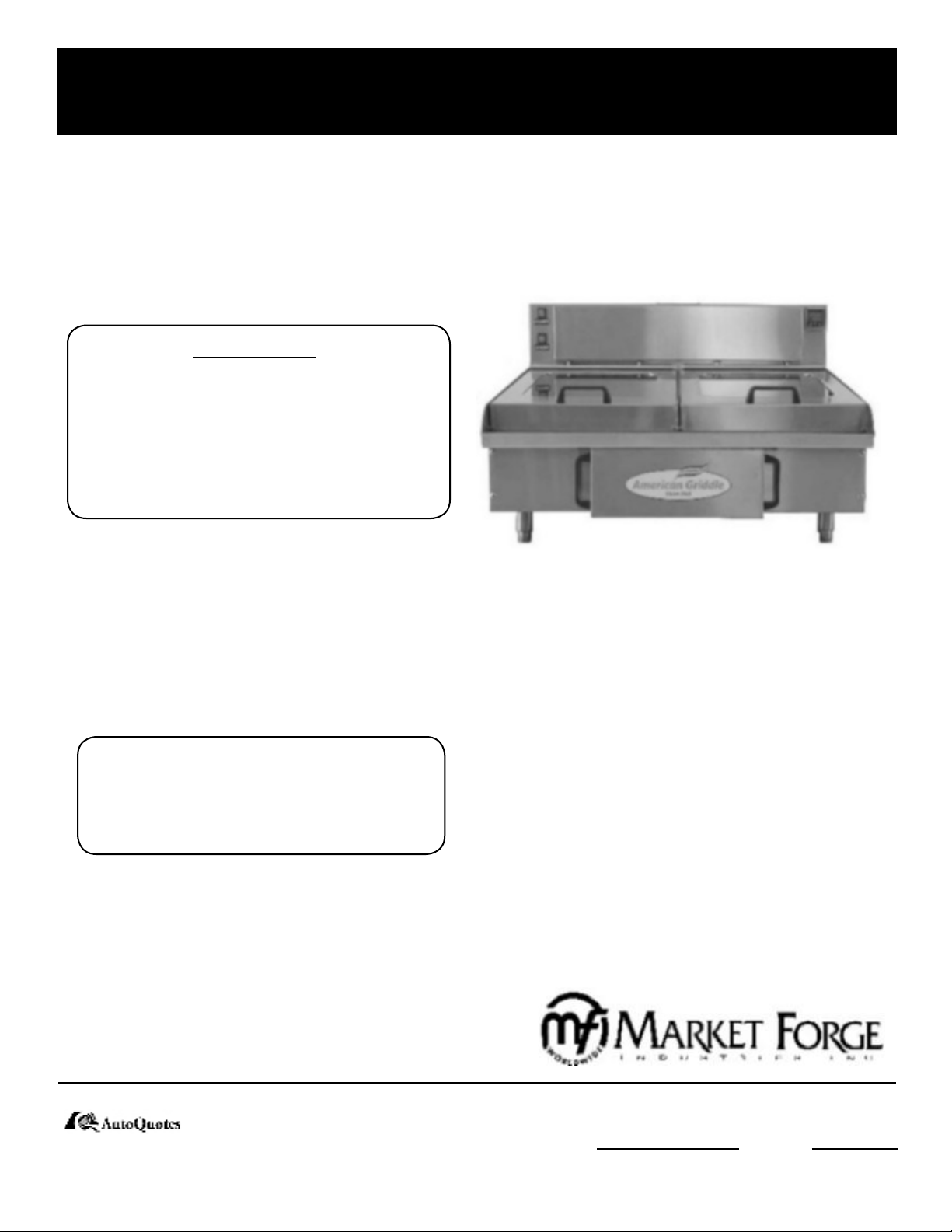
PURR-FECT HEIGHT 2’, 3’ & 4’ ELECTRIC STEAM
SHELL GRIDDLE & STEAM GRIDDLE
OWNER’S MANUAL
WARNING:
NEVER MAKE ANY REPAIRS
OR ADJUSTMENTS TO THE
GRIDDLE/OVEN WHEN HOT
OR IN OPERATION. THIS CAN
RESULT IN SERIOUS INJURY.
STEAM PRESSURE MUST BE
REDUCED TO 0 PSI BEFORE
ATTEMPTING REPAIRS!
2’ MODELS:
MFHP2
•
MFHPS2 (with Steam Lid)
•
3’ MODELS:
MFHP3
•
MFHPS3 (with Steam Lid)
•
4’ MODELS:
MFHP4
•
MFHPS4 (with Steam Lid)
•
Form Number: S-6039 01/07
Printed in U.S.A. 35 Garvey Street l Everett l MA l 02149
Tel: (617) 387-4100 l Toll Free: (888) 698-3188
Fax: (617) 387-4456 l Outside MA Fax: (800) 227-2659
E-Mail: CUSTSERV@mi.com l Website: www.mi.com
An Employee Owned Company
Page 2

TABLE OF CONTENTS
INTRODUCTION 1
INSTALLATION 1
GENERAL 1
CLEARANCES 1
WATER CONNECTION 1
ELECTRICAL CONNECTION 2
ELECTRICAL SPECIFICATION AND PLUG TYPES 2
GRIDDLE SPECIFICATIONS 2
FILLING THE BOILER WITH WATER 3
TURN OFF WATER SUPPLY 3
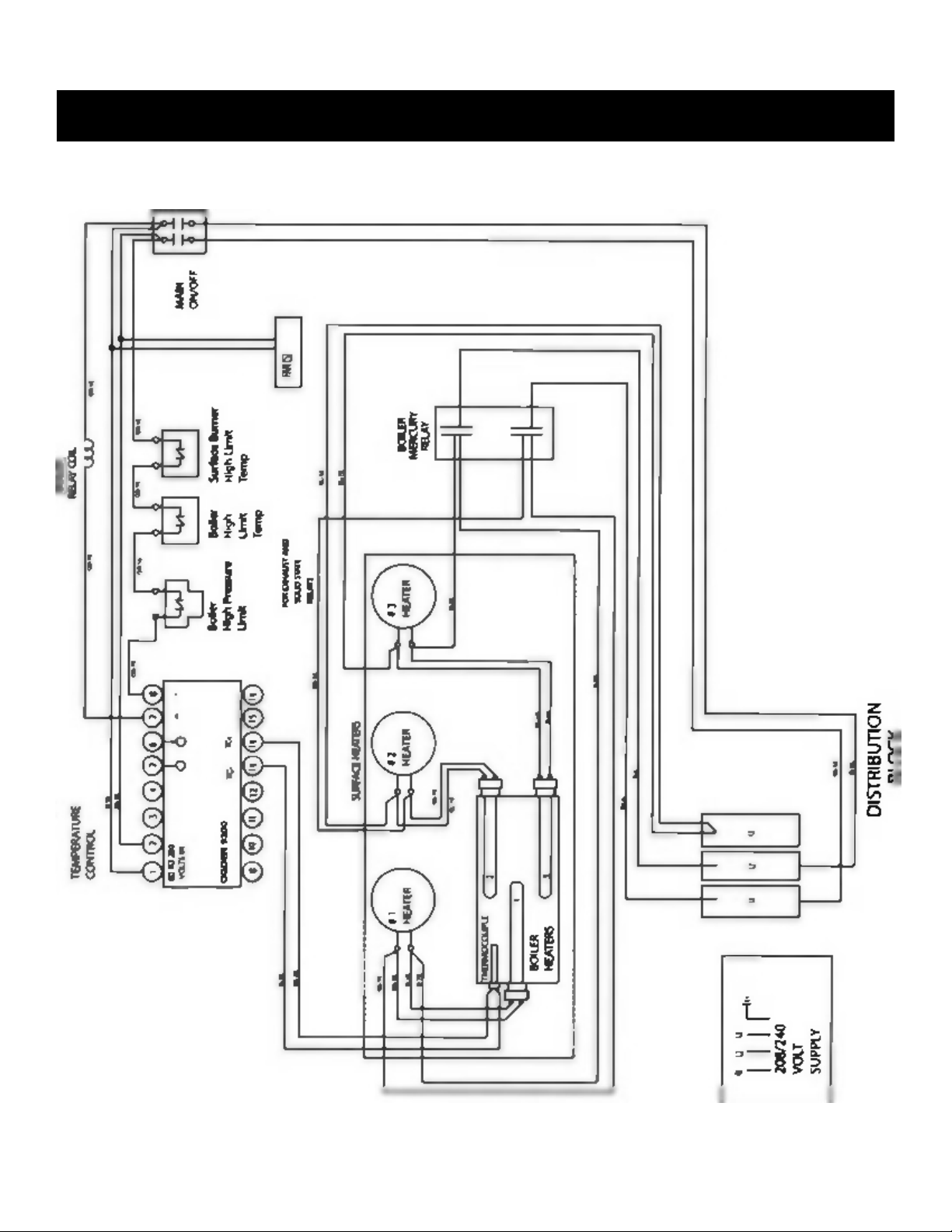
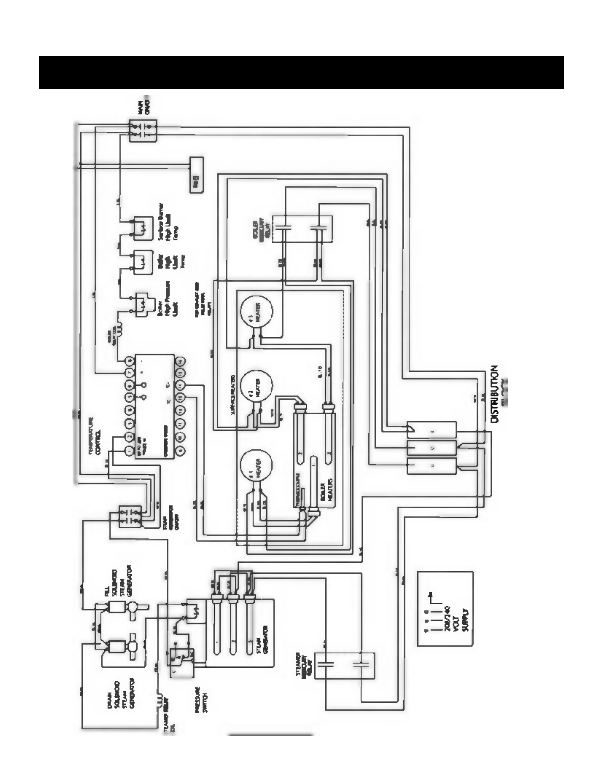
WIRING DIAGRAM 4
OPERATION 6
SETTING THE GRIDDLE 6
GRIDDLE SHUT DOWN PROCEDURE FOR UN-HEATED STORAGE 6
HOT TO SET TEMPERATURE 6
GRIDDLE CLEANING AND SEASONING 7
GRIDDLE COOKING GUIDE AND TIMES 8
TROUBLE-SHOOTING 9
CLEANING / PREVENTIVE MAINTENANCE 10
DE-SCALING STEAM GENERATOR 10
ILLUSTRATIONS 11
APPENDIX 22
i
Page 3
INTRODUCTION
The high performance Market Forge 2’, 3’ and 4’ Purr-fect Height Electric Steam Shell Griddles and Steam Griddles
create a new class of steam cooking equipment. More heat is delivered per square inch than any other griddle and assures
food safety. Additionally, steam is injected into the cooking compartments. This technology allows the food to be cooked
from both sides, dramatically decreasing cooking times and allowing for broader menu items. These items include seafood, stir-fry, vegetables and pork. With the glass window in the cooking lids, food can be observed while cooking.
INSTALLATION
GENERAL: Once the unit is installed it must be elec-
trically grounded and comply with local codes, or in the
absence of codes with the National Electrical Code ANSI
NFPA 70-1999. Installation in Canada must comply with
CSA Standard C22. NO. 109-M1987.
CLEARANCES: Allow at least a three in clearance between the back of the unit and any wall obstruction for
proper ventilation, room for plumbing and electrical connections. The ventilation opening on the back of the griddle must have access to cool air. Griddle needs to be placed
on a level surface to provided ultimate performance. A nonlevel unit could lead to heating element damage.
THIS PROCEDURES SHOULD BE FOLLOWED BY
QUALIFIED PERSONNEL ONLY. DAMAGE WILL
VOID WARRANTY!
All griddles are shipped with a de-scaling filter. Installing
the de-scaling filter according to the manufacturers instructions. See manual included with de-scaler. If de-scaler filter
is not included with the griddle when shipped, contact the
factory. Failure to use approved de-scaler system may void
warranty.
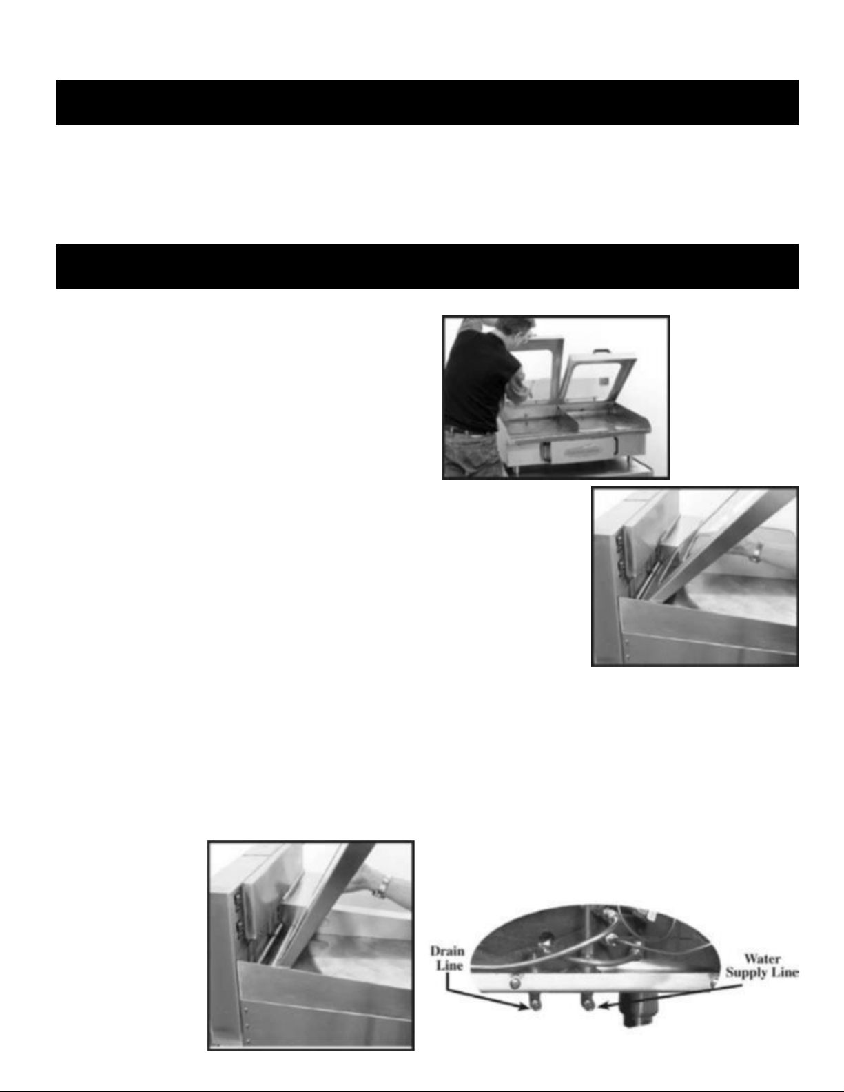
TO INSTALL:
Unpack carefully. Remember to report any damage to
1.
the freight company immediately.
Do not remove any tags or labels until the unit is in-
2.
stalled and working properly.
Set the unit on a level floor.
3.
Install lids as shown in figures 1 through 3.
4.
CAUTION:
Glass Doors!
Use extra caution
when unpacking.
Figure 1
Lift lid with both
hands and set para llel to back of unit.
Figure 2
Figure 3
Once lid is securely
seated under counterweight bar, lower lid
slowly parallel to surface
of griddle.
WATER CONNECTION:
Connect to cold waterline, 1/4” tubing. DO NOT CONNECT
TO HOT WATER SOURCE! Waterline pressure should be
30 PSI minimum. Recommended 1/4” stainless steel braided
hose for water supply line. Dp not use transparent water tubing. Connect 1/4” tubing to drain fitting and run to drain location.
A water de-scaling filter system must be installed to comply
with warranty. If you do not have your own water de-scaling
and filter system contact our factory immediately.
Slide lid until lift flange
on lid is under counterweight bar.
1
Page 4
INSTALLATION
ELECTRICAL CONNECTIONS:
Electrical supply to unit must conform to the National Electrical Codes. See appliance nameplate for service requirements.
For proper connection of field wiring to junction box, see the wiring diagram on page 4-53. Make sure the input voltage
and phase match the requirements shown on the serial plate. (The serial plate is located on the rear of the grill cabinet.)
NOTE: Depending on the model of the griddle it may require two power sources. DO NOT ALLOW ANY TAMPERING
OR ADJUSTMENT OF ANY CONTROL OR WIRING. THE UNIT IS FACTORY SET AND ADJUSTMENT OF ANY
INTERNAL COMPONENT OTHER THAN THE JUNCTION BOX CAN VOID WARRANTY.
ELECTRICAL SPECIFICATION AND PLUG TYPES
MODEL VOLTS PH TOTAL
AMP
2’ 208/240 3 45 60 (3) 2500WATT (3) 3500 WATT-BOILER HEATERS
HZ STEAMER HEATERS @
16.8 AMPS
BOILER & SURFACE HEATERS
@ 29 AMPS
(3) 1500 WATT-SURFACE HEATERS
STEAMER HEATERS @
18 AMPS
3’ 208/240 3 58 60 (3) 3500 WATT (3) 3500 WATT-BOILER HEATERS
STEAMER HEATERS @
18 AMPS
4’ 208/240 3 85 60 (3) 4500 WATT (3) 3500 WATT-BOILER HEATERS
BOILER & SURFACE HEATERS
@ 40 AMPS
(3) 1500 WATT-SURFACE HEATERS
BOILER & SURFACE HEATERS
@ 40 AMPS
(3) 1500 WATT-SURFACE HEATERS
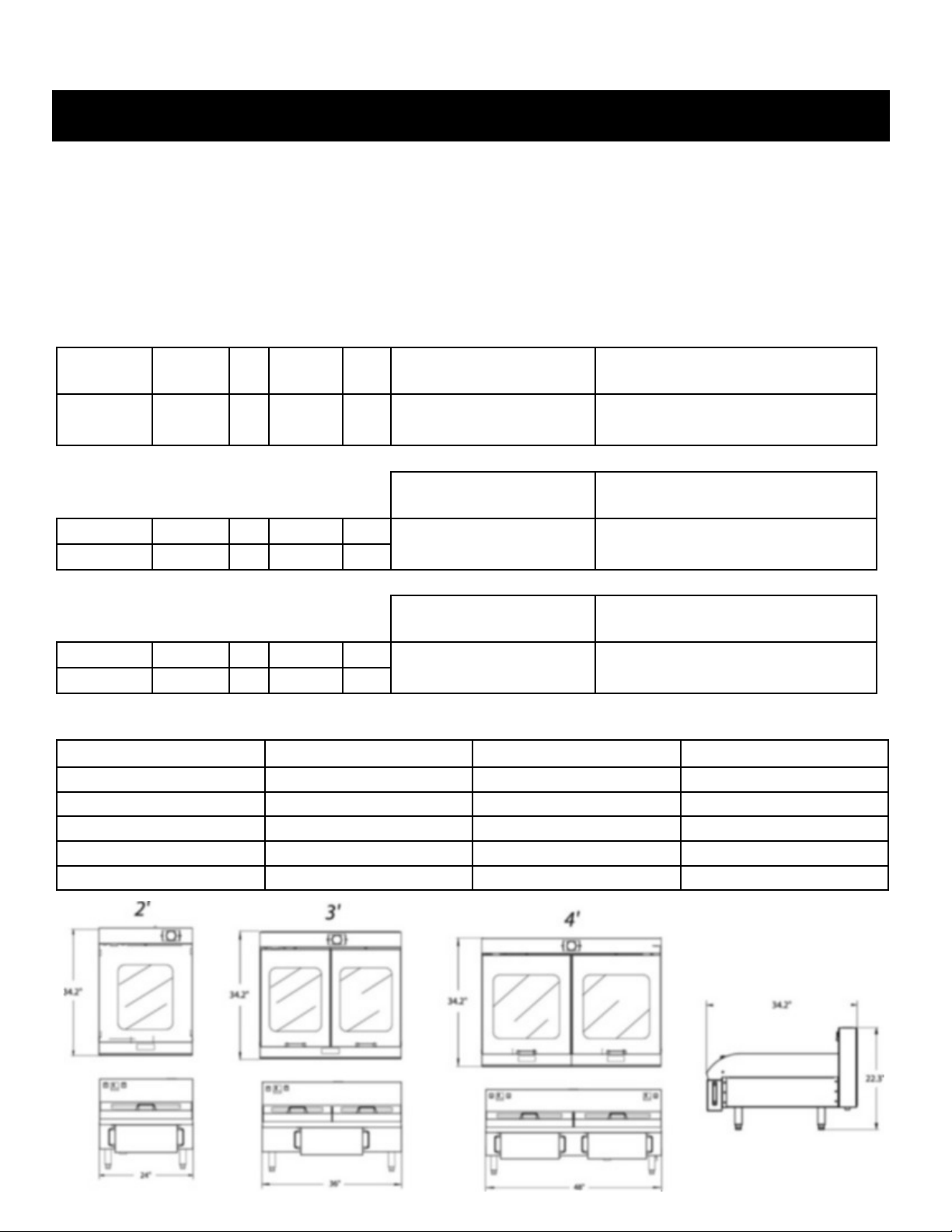
GRIDDLE SPECIFICATIONS
2’ 2’ 4’
Griddle Surface 23.8” Wide x 26.5” Deep 35.8” Wide x 26.5” Deep 47.8” Wide x 26.5” Deep
Cooking Compartments 1 1 2
Temperature Zone 1 1 2
Exterior Dimensions 24” W x 34.2” D x 22.3” H 36” W x 34.2” D x 22.3” H 48” W x 34.2” D x 22.3” H
Max Operating Temperature 390oF 390oF 390oF
2
Page 5
INSTALLATION
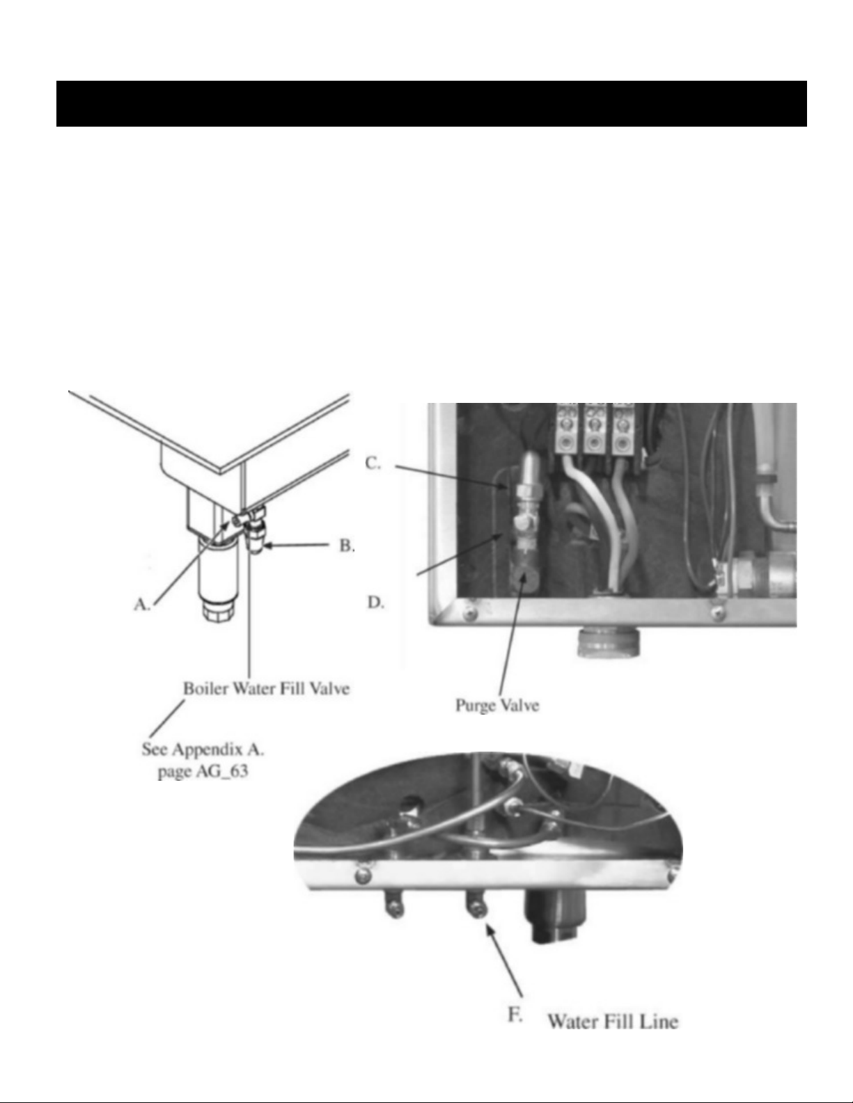
FILLING BOILER WITH WATER:
CAUTION: MAKE SURE POWER IS OFF AND GRIDDLE IS COOL.
TURN OFF WATER SUPPLY:
Locate boiler water fill valve located front right of the griddle and remove caps (A & B). Locate purge valve
left back of griddle inside power head and remove caps (C & D). Detach existing water fill hose rear of
unit (F) and attach to boiler water fill located front right of griddle (A). Open valve; allow water to run until
water exits purge valve then close purge valve. Close fill valve. Turn water line at its source and disconnect.
Replace caps on all fittings.
3
Page 6
INSTALLATION
4
Page 7
INSTALLATION
5
Page 8

OPERATION
STARTING THE GRIDDLE:
1. Turn on the main power switch for the
griddle.
a. Main power switch.
b. Power switch on the steam
generator.
2. Set control to the desired temperature.
(265oF minimum to cook, heating period is 20 mins.)
3. Allow griddle to reach set point temperature before
beginning to cook. Heating period is 20 mins.
STARTING AUTOMATIC STEAM INJECTION LIDS
WHEN COOKING:
NOTE: Steam injection will not turn on unless lid is lowered
to closed position and pushed towards back of griddle.
Slightly lifting lid and pulling forward will turn off steam.
HOW TO SET TEMPERATURE:
A. Actual temperature reading.
B. Desired set temperature.
C. Factory set program function.
1. Increase desired set temperature.
2. Decrease desired set temperature.
Pushing lid back will turn steam back on.
GRIDDLE SHUT DOWN PROCEDURE FOR UNHEATED STORAGE:
1. Disconnect water and electrical supply.
2. Water will need to be drained and blown out with com pressed air from all components. It is recommended that
a qualified service agent do this.
OGDEN CONTROLLER 9200
Tap button 1 or 2 (up or down key) for less than 1 sec-
•
ond.
All four temperature digits on the lower display will light
•
with the first digit being brighter.
Advance to the digit you want to change by pressing but-
•
ton 1 or 2 (up or down key) for less than 1 second.
To change the value of the digit hold in the up or down
•
key. After 10 seconds the new value will be entered and
the display will read normally.
Tap either arrow button once to highlight all digits.
•
Once desired digit is highlighted hold the proper button
•
in to increase or decrease digits.
Refer to page 6 for illustrated help.
6
Page 9

OPERATION
GRIDDLE CLEANING AND SEASONING:
1. Seasoning is a process to protect the griddle from rusting and prevent foods from sticking to the surface
during cooking.
2. Use only a small amount of vegetable oil, such as Wesson. Spread is around evenly (avoiding Corners)
while heating.
3. Pour salt over griddle surface and rub in circular motions over entire griddle surface with a handle and
grill screen.
4. When the oil begins to smoke, turn off griddle and squeegee off salt and oil. Let griddle cool for a 30
minute period.
5. Repeat the process one of two more times.
6. Re-season as needed.
7. Do not use water, soaps or griddle cleaners to clean griddle surface. If you do, you must re-season griddle
surface. In between normal cooking operation scrape griddle with a plastic scraper to keep clean. DO
NOT THROW COLD WATER ON A HOT GRIDDLE! it may cause the griddle surface to warp.
7
Page 10

TYPE PRODUCT PORTIONS MINUTES
Beef Hamburger 4 oz. 3-4
Beef Hamburger 6 oz. 5-6
Beef Hamburger 8 oz. 6-8
Beef Hamburger 12 oz. 9
Poultry Chicken Breast 4 oz. 4
Poultry Chicken Breast 5 oz. 5
Poultry Chicken Breast 6 oz. 6
Poultry Thighs 6 oz. 6
Poultry Quarters 10 oz. 20
Poultry Quarters Marinated 10 oz. 16-18
Seafood Crab Legs 1 lb. 12
Seafood Lobster 6 oz 6
Seafood Shrimp 16/20 1 oz 1 1/2
Seafood Snow Crab 1 lb. 8-9
Seafood Scallops - Cape 4 oz 3
Seafood Crab Cakes 4 oz 4
Seafood Crab Stuffed Mushrooms 6 oz 6
Fish Haddock 4-5 oz. 3-4
Fish Yellow Fin Tuna 5 oz. 4
Fish Salmon 8 oz. 4-5
Fish Cod 4 oz. 4
Eggs Fried 2 Each Under 1
Eggs Omelet 3 Eggs Under 1
Eggs Scrambled 2 Each Under 1
Breads Grilled BLT 7-8 oz. 5
Breads Grilled Cheese 4.5 oz. 2
Breads Reuben Sandwich 7-8 oz. 4
Breads Tortilla 20” 20
Breads Potato Pancakes 4 oz. 4
Breads French Toast 2-3 oz. 3
Breads Pattie Melt 4 oz. 4
Breads Quesadillas 12” Under 1
Sausages Patties / Thick 2 oz. 5
Sausages Patties / Thin 1/4” 2 oz. 3
Sausages Links 1 oz. 6-8
Sausages Brats 4 oz. 7
Sausages Hot Dog 5/1 6
Sausages Polish 4 oz. 6
Sausages Italian Rope 16 oz. 7 1/2
GRIDDLE COOKING GUIDE AND TIMES
Vegetables Broccoli Florets 16 oz. 6-7
Vegetables Asparagus 11 oz. 5-6
Vegetables Mushrooms, Large Whole 16 oz. 6-7
Vegetables Mushrooms, Sliced 16 oz. 3
Vegetables Peppers & Onions 1/2” Cut 24 oz. 3
Vegetables Carrots 16 oz. 6-7
Vegetables Corn 16 oz. 5
Pork Chop Center Cut 6 oz. 6
Pork BBQ Rib Slab 6 or less
Pork Cutlet 4 oz. 4
Lamb Chops / Thick 3/4” 1 1/2-2 oz. 4
8
Page 11

TROUBLE-SHOOTING
The griddle is designed to operate smoothly and efficently is properly maintained. However, the following is
a list of checks to make in the event of a problem.
Wiring diagrams are furnished inside the service panel as well as in this manual.
IF AN ITEM ON THE LIST IS FOLLOWED BY AN (*), THE WORK SHOULD BE DONE BY A QUALIFIED SERVICE AGENT.
PROBLEM PROBABLE CAUSE REMEDY
LOW WATER IN BOILER 1. Steam system leak. 1. Repair leak.*
HEATER(S) NOT WORKING Unit not wired properly.
GRIDDLE HOTTER THEN SET POINT Temperature controller out of cali-
GRIDDLE HEATS UP TOO SLOWLY Heater(s) not working.
GRIDDLE NOT HEATING UP Temperature control not set high
UNEVEN SURFACE TEMPERATURE Air in system.
NO POWER Power switch off.
NO STEAM COMES OUT OF NOZZLE Start up procedure not done.
STEAM GENERATOR WATER LOW Water supply to steam generator off.
NOT ENOUGH STEAM PRESSURE Heater(s) not working.
HEATER(S) NOT WORKING Wired incorrectly.
1.
Heater(s) bad.
2.
Contactor or solid state relays not
3.
working.
Failed temperature controller.
4.
1.
bration.
Thermocouple sensor defective.
2.
Solid stare relay(s) stuck on.
3.
Failed temperature controller.
4.
1.
Too much water in boiler.
2.
1.
enough.
Low water in boiler.
2.
Failed temperature controller.
3.
Heater(s) not working.
4.
1.
Low water in boiler.
2.
1.
Not plugged in.
2.
Breaker off or tripped.
3.
1.
Steam generator low on water.
2.
Lid not closed.
3.
Heater(s) not working.
4.
Steam solenoid defective.
5.
1.
Water solenoid plugged or defective.
2.
1.
Pressure switch out of adjustment or
2.
defective.
Pressure switch waterlogged.
3.
1.
Heater(s) bad.
2.
Pressure switch out of adjustment or
3.
defective.
Pressure switch waterlogged.
4.
Check wiring.*
1.
Replace heater(s).*
2.
Repair or replace.*
3.
Replace temperature controller.*
4.
Recalibrate temperature controller.*
1.
Replace thermocouple.*
2.
Replace solid state relay(s).*
3.
Replace temperature controller.*
4.
Purge air per instruction.
1.
Remove excess water.
2.
Adjust to desired temperature.
1.
See ”low water in boiler”.
2.
Replace temperature controller.*
3.
See “heater(s) not working”.
4.
Check water level and purge air from
1.
system. Check for leaks.
Check water level in boiler. Add
2.
water if needed.
Turn on power switch.
1.
Check plug.
2.
Check breaker.
3.
Check for shorts.*
4.
Perform “start up procedure”.
1.
See “steam generator water low”/
2.
Lid must be closed to activate steam.
3.
See “heater(s) not working”.
4.
Replace.
5.
Check water supply.
1.
Repair or replace.*
2.
See “heater(s) not working”.
1.
Repair or replace.*
2.
Restore air trap for pressure switch
3.
and repair air leak.
Check wiring.*
1.
Replace heater(s).*
2.
Repair or replace.*
3.
Restore air trap for pressure switch
4.
and repair air leak.
9
Page 12

CLEANING / PREVENTIVE MAINTENANCE
Cleaning procedures for griddle and stainless steel surfaces:
1. Suggested tools: Rubber Squeegee, rubber or plastic
scrapers, plastic wool, cloth, griddle cleaner and sanitizer.
2. Precautions: Before any cleaning, reduce temperature to
325oF.
3. Remove glass lids and divider. CAUTION: LIDS AND
DIVIDER MAY BE HOT!
4. Clean all food contact surfaces as soon as possible after
use, preferably while the griddle is still hot. Scrape
griddle with a spatula to remove loose food debris. BE
CAREFUL NOT TO SCRAPE THE GRIDDLE SURFACE WITH METAL UTENSILS.
5. Prepare a solution of griddle cleaner as instructed by the
supplier, clean the griddle surface thoroughly.
6. To remove materials stuck to the surface use a brush,
sponge, cloth, rubber scraper, plastic scraper or plastic
wool along with the detergent solution. To minimize the
effort required in washing let the detergent solution sit
on the unit and soak into the residue or heat the detergent
briefly. DO NOT use any abrasive materials or metal
implements that might scratch the surface. Scratches
make the surface hard to clean and provide places for
bacteria to grow. DO NOT use steel wool which may
leave particles imbedded in the surface, causing corrosion and pitting.
7. Rinse the griddle thoroughly with clean water.
8. When the equipment needs to be sanitized, use a sanitizing solution. Contact our factory to ask which sanitizing
solution is best. Follow the instructions on the sanitation solution bottle and apply to the unit after it has been
cleaned and drained. Rinse off the sanitizing solution
thoroughly with clean water.
9. Turn the griddle on and allow surface to heat up enough
to dry thoroughly. Once dry, coat the griddle surface
with a thin layer of liquid shortening.
Cleaning the glass lids:
A. During daily cooking, the glass lid window can be
cleaned using a rubber squeegee and a wet towel.
B. The lids can be removed and placed into the dish-
washer for easily cleaning.
WARNING:
KEEP WATER AND SOLUTIONS AWAY FROM CONTROL PANEL! NEVER HOSE OR SPRAY
CONTROL PANEL OR OUTSIDE OF UNIT!
Add 32 oz. of de-scaling solution & 3 qts. of clean water
DE-SCALING STEAM GENERATOR:
CAUTION: DO NOT USE “LIME AWAY” OR OTHER HIGH
ACID DELIMING SOLUTIONS (if they cause excessive foaming).
USE WHITE VINEGAR OR CITRUS BASE DE-SCALING
CHEMICALS. Use a minimum of 32 oz. of citrus de-scaler solution.
De-scaling os steam generator: (Every 60 days, more if you have
hard water) This procedure must be done while steam generator is
off and all lids are pulled forward and in the closed position.
Power off steam generator.
1.
Remove steam cap inspection plate located on topside of
2.
power head.
Ensure release of pressure by rotating 1/4 turn. Remove cap.
3.
Drain water from steam generator using valve located at the
4.
bottom center of griddles backside.
Close drain valve after draining is complete.
5.
6.
through fill opening.
Replace cap by tightening fully.
7.
Power on steam generator.
8.
Allow generator to reach operating temperature.
9.
Close lids and pull forward slightly to deactivate steam injec-
10.
tion. Allow steam generator to cycle for 15-20 minutes.
Push lids forward to allow steam injection to operate for 10
11.
minutes to allow de-scaling of steam nozzle lines.
Power steam generator off and allow 5 minutes for pressure
12.
relief.
Repeat steps 3-6.
13.
Add 1 gallon clean water through fill opening.
14.
Repeat steps 5-6 to flush de-scaling solution.
15.
Again add 1 gallon of clean water through fill opening.
16.
Replace cab by tightening fully.
17.
Power on steam generator as normal for continued operation.
18.
Alternate method:
turn power off to steam generator.
1.
Let solution set overnight.
2.
Follow steps 2-18 above.
3.
10
Page 13

ILLUSTRATIONS
4’ Griddle Power Head
11
Page 14

ILLUSTRATIONS
4’ Griddle Power Head
ITEM
NO.
1 90485 POWER SWITCH - RIGHT SIDE
2 90520 OGDEN 9200 CONTROLLER 240 VOLT - RIGHT SIDE
3 90645 MERCURY SWITCH BOILER & CONDENSATION HEATERS - RIGHT
4 09645 MERCURY SWITCH BOILER & CONDENSATION HEATERS - LEFT
5 91155 SIPHON HOSE FROM STEAM GENERATOR
6 90645 MERCURY SWITCH STEAM GENERATOR HEATERS
7 90760 STEAM GENERATOR PRESSURE CAP
8 91158 STEAM GENERATOR FILL TUBE
9 90600 BOILER HIGH LIMIT THERMOSTAT @ 450oF - RIGHT SIDE
10 90600 BOILER HIGH LIMIT THERMOSTAT @ 450oF - LEFT
11 90520 ORDEN 9200 CONTROLLER 240 VOLT - RIGHT SIDE
12 90485 POWER SWITCH - RIGHT SIDE
13 90485 STEAM POWER SWITCH
14 90303 COOLING FAN
15 90115 WATER FILL SOLENOID @ 240 VOLT
16 90650 PRESSURE REGULATOR
17 91445 SHRADER VALVE
18 ~NPN~ ----- --------------------------------------------------------------------------------------------
19 ~NPN~ ----- WATER FILL CAPILARY TUBE
20 90845 WATER FILL CONNECTION 1/4”
21 90845 WATER DRAIN SOLENOID
22 909850-90855 STEAM GENERATOR HEATER(S)
23 / 24 90570 2’ - HEATER
25 91155 STEAM GENERATOR SIGHT GLASS
26 90595 SNAP DISK
27 90657 DRAIN
28 ~NPN~ ----- STEAM GENERATOR
29 ~NPN~ ----- STEAM INJECTOR TUBES
30 91158 HEATERS (2) LEFT - (refer to 23 / 34)
31 91150 LOW PRESSURE SWITCH
32 90330 POWER TERMINAL BLOCK
33 90780 HIGH PRESSURE SAFETY SWITCH 250 PSI FOR BOILER
34 90695 PURGE VALVE - RIGHT & LEFT SIDE
35 90303 COOLING FAN
AG
PART NO.
90575 3’ - HEATER
90489 4’ - HEATER
90596 O-ring
PART
NO. DESCRIPTION
12
Page 15

ILLUSTRATIONS
4’ Griddle Bottom View
Controller Wiring Chart
1. N/A
2. N/A
3. N/A
4. To Thermo Probe - Red Wire (-)
5. To Thermo Probe - White Wire (+)
6. To Power Source
7. To Power Terminal Strip
8. To Solid State Relay
9. To Solid State Relay
10. N/A
Controller Rear View
13
Page 16

ILLUSTRATIONS
3’ Griddle Power Head
14
1. Controller
2. Mercury Switch
3. Steam Generator Fill Assy
4. High Limit Thermostat
5. Fan
6. Steam Generator Power Switch
7. Power Switch
8. Water Fill Solenoid
9. Boiler Access Panel (Heaters)
10. Heater Exchange
11. Steam Generator Solenoid
12. Steam Generator
13. Ground Block
14. Power Cord Grip
15. Power Terminal
16. Fan
Page 17

ILLUSTRATIONS
3’ Griddle Bottom View
15
Page 18

ILLUSTRATIONS
2’ Griddle Power Head
16
Page 19

ILLUSTRATIONS
2’ Griddle Bottom View
17
Page 20

ILLUSTRATIONS
Steam Generator Assy
19
Page 21

ILLUSTRATIONS
1. Power Head
2. Steam Generator Fill Cap Plate
3. Lid Counter Weight Assy
4. Conttroller
5. Heat Exchanger - Steam Generator
6. Back Plate
7. Right Splash Plate
8. Right Skirt
9. Right Skit Bracket
10. Water Fill Valve - Boiler
11. Griddle Plate
12. Front Waste Trap Channel
13. Front Skirt
14. Waste Trap
15. Left Skirt Plate Bracket
16. Left Splash Plate
17. Left Skirt
18.Lid Divider Rail
19. Lid Assy
20
Page 22

ILLUSTRATIONS
1. Water Fill Valve
2. Surface Plate Retaining Plate
3. Air Tank Assy
4. Surface Heaters - 1500 Watts
5. Serpentine Steam Channel
6. Rupture Disk
7. 5” Adjustable Stainless Steel Legs
8. Boiler Reservoir
9. Griddle Plate
10. Boiler Heaters
11. Controller Thermostat Probe
12. Condensate Return Tube
13. Condensate Return Reservoir
14. NPT Plug
21
Page 23

APPENDIX
22
 Loading...