

Page 1
Page 2
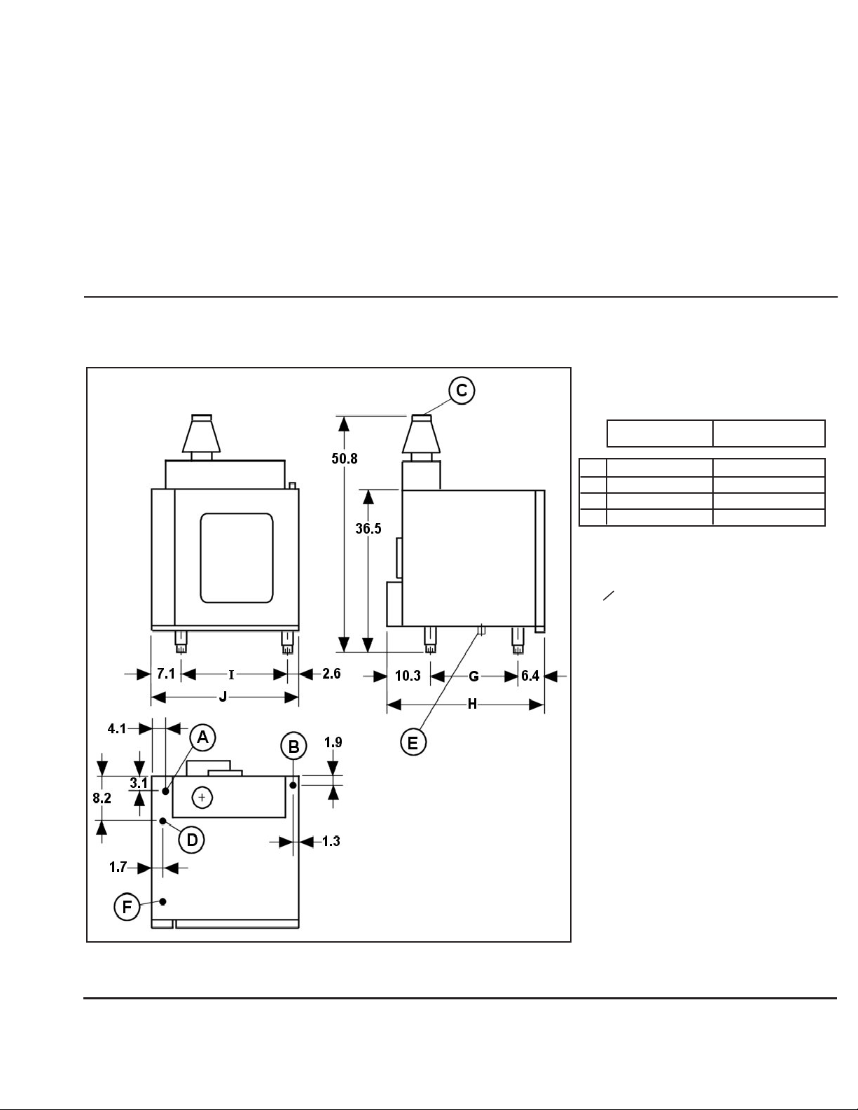
TABLE OF CONTENTS
1. INSTALLATION ................... 1-6
1.1Diagrams
1.2 Positioning
1.3 General Specifications
1.4 Electrical Connection
1.5 Water Inlet
1.6 Drainage
1.7 Gas Inlet
1.8 Conversaion to different gases
1. INSTALLATION
2. OPERATION........................ 7-9
2.1 Using the Combioven
2.2 Control Panel
2.3 Switching on the Combioven
3. MAINTENANCE................ 10-11
3.1 Day-To-Day Cleaning
3.2 Cleaning the Steam Generator
3.3 Trouble-Shooting
1.1 Installation Diagrams
MFHMG-10/11
G.
H.
I.
J.
21.0
37.8
25.6
35.4
MFHMG-10/21
29.1
45.9
30.3
40.2
Figure 1. (MFHMG-10/11 & 10/21 Dimentions)
A. RG 3/4" Filtered Water Line.
B. RG 1" General Oven Drainage.
C. O 120 Fumes Outlet.
D. Electrical Supply Input Connection.
E. Drainage Cleaning Cap.
F. RG 1/2" Gas Inlet.
1
Page 3
1. INSTALLATION
1.2 Positioning
The appliance should always be installed and connected to the electricity and gas
supplies by an authorized service engineer. Any subsequent adjustments or conversions
should also be carried out only by qualified personnel.
The standards in force in the country in which the appliance is to be installed should
always be met.
m The combi oven comes with a draft hood as standard. Therefore, the oven may be
vented either under a ventilation hood or by using a type B vent.
m Locate the appliance in properly ventilated premises in order to avoid an excessive build-up of steam.
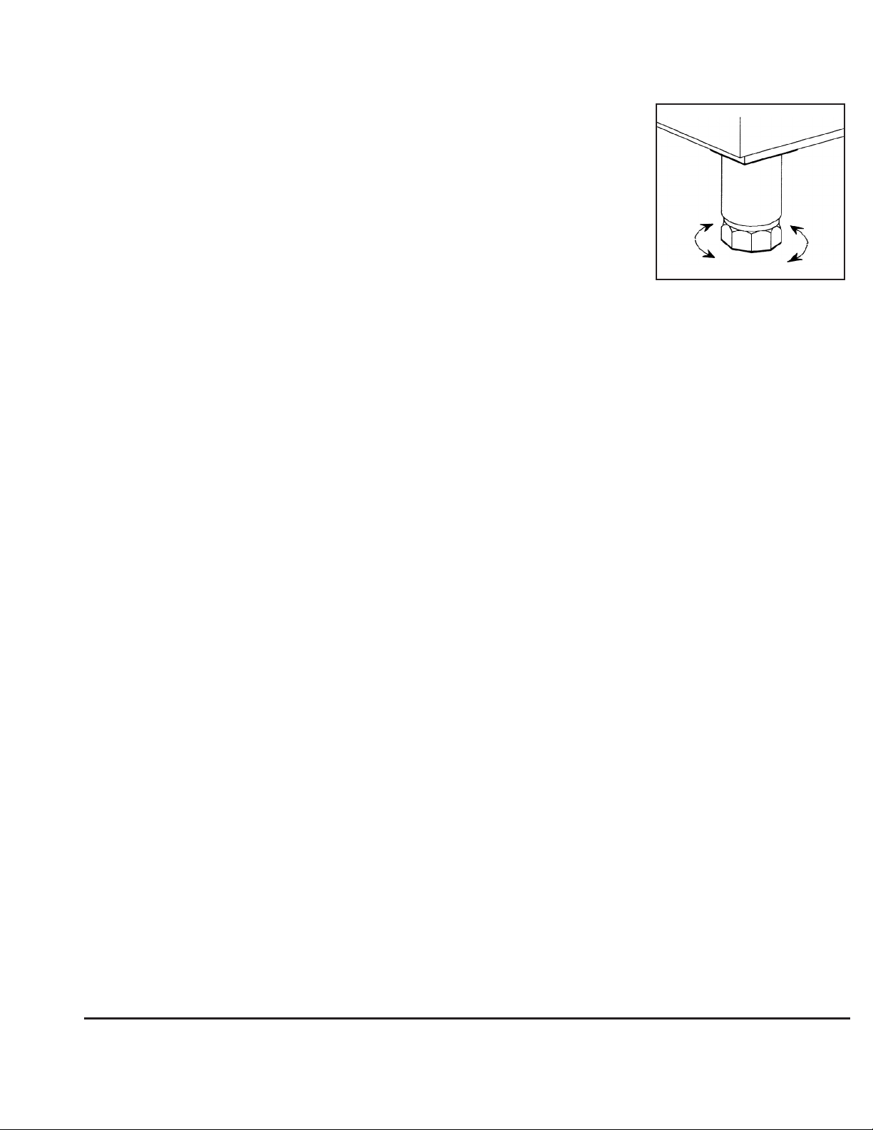
m Level and adjust the height of the appliance. This can be done by turning the bottom part of the four adjustable feet
(see Fig. 2).
m The combi oven may be installed on a stand. The instructions to assemble the stand and mount the combi oven on
the stand are provided with the stand. The stand could also be used to store sheet and steam pans.
m The appliance has ventilation openings on the left-hand side; so there should be at least 4" of space between the
appliance and any walls or other appliances for the air to circulate freely in that area.
m All combi ovens mounted on stands come with casters as standard. However, combi ovens mounted on stands with
adjustable feet must have at least 18" (45.7 cm) of clearance from the left side and the back for servicing access.
Figure 2.
m The combustible and non-combustible construction clearances should be 0" from the back and 4" from the left and
right side each.
m The appliance should not be positioned in such a way that it can be affected by the steam or heat from other
appliances nearby, especially on the left-hand side.
m The back panel of the appliance should always be in position and properly screwed on, for safety reasons and for the
oven to work properly.
m Keep the oven area free and clear of combustibles.
m Do not obstruct the flow of combustion and ventilation air.
m Keep this manual for future reference.
m Installation shall be made with a connector that complies with the Standard for Connectors for Moveable Gas
Appliances, ANSIZ21.69 (or latest edition) and a quick-disconnect device that complies with the Standard for QuickDisconnect Devices for Use with Gas Fuel, ANSIZ21.41 (or latest edition)
m Adequate means must be provided to limit the movement of the appliance without depending on the connector and
the quick-disconnect device or its associated piping to limit the appliance movement.
m The restraining means may be attached to the back of the stand.
2
Page 4
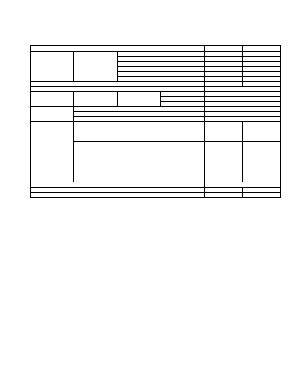
MFHMG-10/11 MFHMG-10/21
35.4 40.2
37.8 45.9
36.5 36.5
50.8 50.8
25.6 30.3
21.0 29.1
335.1 471.8
50
Cable Section
60
Main Switch Fuse
Hz
Differential Device
18.000 24.000
71.430 95.240
18.8 25.11
1.48 1.97
1.46 1.94
2 2.66
2.32 3.09
4.86 6.48
2.86 3.81
3.14 5
Performance % 90 % 90 %
85 85
Maximum No. 10 20
Trays --- 10
110.2 220.4
3.9 7.9
Water Inlet Pressure PSI
Maximum Loading Weight lbs.
Approximate Water Consumption (gph)
7.1 --- 113.8
Hot Air
Steam (%)
GN 1-1
GN 2-1
Kg/h (29 mb)
Butano (G-30)
m / (8 mb) Town Gas (G-150)
Kg./ (37 mb) Propane (G-31)
m_/ (20 mb) Natural (G-20)
m / (25 mb) Natural (G-25)
m / (8 mb) Town Gas (G-110)
m / (8 mb) Town Gas (G-130)
Gas Power
Kcal/h. (Hs)
BT (Hs)
KW (Hs)
10 A
30 mA
Supply Voltage
220/240V 1N
Net Weight lbs.
Electrical Power KW.
0.55 KW
2 x 1.5 + T
MODEL
Depth V
Width U
Height with Vent Z
Height without Vent W
Depth Y
Width X
INCHES
Outer Dimensions
1.3 General Specifications
Nominal
Consumptions
1. INSTALLATION
1.4 Electrical Connection
The electrical connection of the appliance should always be carried out by an authorized service engineer.
The current standards in force in each country regarding connections to electric mains should be taken into account.
m The electrical diagram adhesive label is located inside the control compartment.
m Check that the main’s voltage corresponds to that indicated on the specifications plate.
m This oven is equipped with a 3-prong (grounding) plug for your protection against shock hazard and should be
plugged directly into a properly grounded 3-prong receptacle. Do not cut or remove the grounding prong from this
plug.
m Fit a switch for all phases close to the appliance, with a minimum distance between contacts of 3 mm. This switch
must have fuses.
m This appliance, when installed, must be electrically grounded in accordance with local codes; or, in the absence of
local codes, in accordance with the National Electric Code, ANSI/NFPA No. 70 (or latest edition).
The manufacturer cannot accept any responsibility for damage caused from a failure to observe these grounding
instructions.
3
Page 5

1. INSTALLATION
m It is necessary to completely remove the control panel to get to the terminal strip. Pass the insulated cable through
the gland located under the control panel at the bottom (Fig. 1 [D]) and connect as shown on the strip.
m Very Important: Before replacing the control panel, secure the power cable well to the compression gland.
m When a number of appliances are installed in line, they should all be grounded at the point provided for that purpose,
on the base of the oven at the back.
1.5 Water Inlet
The current standards in force in each country regarding connections to water mains should be taken into account
m Connect to the water mains via the appliance inlet connector indicated in Fig. 1 [A], using the hose provided with the
appliance.
m If the main’s water has a hardness of more than 10DF, a water softener should be fitted to the outside of the
appliance.
m The water inlet pressure should be between 25 and 50 PSI. For higher pressures, it is necessary to install a pressure
regulator.
m It is necessary to fit some filters to the appliance’s water inlet, to prevent impurities (which could damage the steam
generator) from getting in to the appliance.
m It is necessary to fit a stopcock before the appliance’s water inlet.
1.6 Drainage
m Connect the appliance’s general drainage outlet at the point
indicated in Fig. 1 [B].
m The connection hose running from the oven’s drainage outlet to the main drains should be steam-resistant
(100°C/212°F).
m The drainage connection should be made as shown in Fig. 3.
Figure 3.
1.7 Gas
The appliance should always be connected to the gas mains by an authorized service engineer.
m The installation must conform with local codes; or, in the absence of local codes, with the National Fuel Gas Code,
ANSI Z223.1 (or latest edition).
m To connect gas to the oven, which has a 1/2" screwed coupling, use an ANSI.B36 pipe with a 1/2" connector.
m The manual shutoff valve supplied with the appliance must be installed at the gas inlet so as to be accessible for
turning on and shutting off all gas to the appliance.
4
Page 6

1. INSTALLATION
m The oven and its individual shutoff valve must be disconnected from the gas supply piping system during any
pressure testing of that system at test pressure in excess of a 1/2 PSIG (3.45 k/PA). Also, the oven must be isolated
from the gas supply piping system by closing its individual manual shutoff valve during any pressure testing of the gas
supply piping system at test pressures equal to or less than 1/2 PSI (3.45 k/PA).
m The oven is factory-adjusted for either 75,000 (model MFHMG-10/11) or 100,000 (model MFHMG-10/21) BTU/hr. at
the pressure indicated. Please read the rating plate on the top of the unit. If this plate is marked for a different gas
than that supplied, notify your dealer immediately. Install the supplied external supply shutoff valve at the gas main
inlet, which is located under the bottom front-left side. Install so that the shutoff valve handle is clearly visible to the
operator.
m Use new iron or steel pipe complying with the latest ANSI Standard for Wrought-Steel and Wrought-Iron Pipe, B36,
properly threaded, reamed, and free of chips, oil, and dirt. If pipe dope is used, apply a moderate amount, leaving two
end threads bare. Pipe dope must be resistant to LP gas. Connect the gas line into the bottom (inlet) side of the gas
supply shutoff valve. The supply pressure must be at least 1" (25 mm) water column higher than the manifold or
regulator pressure for proper functioning of the regulator. If it is not, check the supply pipe for blockage or excessive
pressure drop and make the necessary corrections.
m Perform a gas leak test of all newly made joints as well as those leading to the main gas control valve. Use a soap
solution. Do not use flame.
m Natural gas units are equipped with a pressure regulator factory-adjusted to give 5.5" (140 mm) water column
manifold pressure.
m Propane gas units are equipped with a pressure regulator factory-adjusted to give 10" (254 mm) water column
manifold pressure.
NOTE: Only a licensed gas fitter should make gas line connections.
1.8 INSTALLATION WITH CASTERS
m Installation shall be made with a connector that complies with the Standard for Connectors for Moveable Gas
Appliances, CAN/CGA-6.16, and quick-disconnect device that complies with the Standard for Quick-Disconnect
Devices for Use with Gas Fuel, ANSI Z21.4 or the Standard for Quick-Disconnect Devices for Use with Gas Fuel,
CAN-6.9.
m Adequate means must be provided to limit the movement of the appliance without depending on the connector and
the quick-disconnect device or its associated piping to limit the appliance movement.
m The location(s) where the restraining means may be attached to the appliance shall be specified.
NOTE: Installation of casters is highly recommended at the time of assembling the combi oven stand.
WARNING: Do not try to install casters on a stand that has a combi oven mounted on it. The oven may tilt and cause
serious injuries. It is important to remove the oven safely off the stand prior to installing the casterson the
stand.
m After assembling the combi oven stand, screw each caster into the bottom of each leg of the stand by tilting the
latter.
m Casters must screw fully into the leg in order to be tight.
5
Page 7

1. INSTALLATION
m Apply brakes in front by stepping on the lever on the side of the front casters until it is in the “on” position.
m If permissible, apply brakes in rear also.
NOTE: For installing a gas connector kit refer to the installation instruction provided with the gas connector kit for units
with casters (MF#94-0582) for recommended mounting instructions.
NOTE: See the following figure for a recommended location of an I-bolt (MF#08-7839)
Propane (G-20)
Natural Gas (G-25)
MODEL
MFHMG-10/11 MFHMG-10/21
3.0 3.5
3.0 3.5
1. Control panel fixing slot
2. Gas valve outlet connection
3. Washer
4. Gas injector
5. Air filter
6. Air filter support
7. Gas electrovalve
7A. Outlet pressure adjustment (Maximum)
7B. Outlet pressure connection
7C. Slow rise device (Minimum)
7D. Inlet pressure connection
7E. Coil
8. Differential pressure switch
Figure 4.
6
Page 8

2. OPERATION
2.1 Using the Appliance
m In the event of a power failure, no attempt should be made to operate this oven.
m Before using the appliance for the first time once it has been installed, it is recommended that the inside of the oven
be cleaned with a cloth soaked in soapy water and that it be switched on empty for half an hour, in steaming mode, to
eliminate the smells characteristic of a new oven.
m If this oven is equipped with casters, be aware that there is a restraint on the oven. If disconnecting the restraint is
necessary, reconnect it when the oven is returned to the original installation position.
m Before switching on the oven, check that the grease filter is properly in place and that the water and gas stopcocks
have been opened.
m When the oven is not going to be used for some time, it is recommended that the water and gas shutoffs be closed.
m When opening the oven door, open it just a little bit at first, so that most of the steam can escape safely without hitting
you full in the face. Once most of the steam has escaped, open the door fully.
m To switch on the oven, just turn the top control knob on the control panel to the mode you require.
m The oven will now come on. When the programmed time has elapsed or when the temperature required in the probe
is reached, the oven will turn itself off. If the oven fails to ignite, the luminous button at the bottom of the control panel
will light. After waiting five minutes for a complete shutoff period, press the button for attempted re-light.
m The oven only has one burner, for producing both hot air and steam, thanks to an advanced high technology system.
m The vent opens and closes automatically.
m When the vent is open, the burner heats the air inside the oven,
producing hot air.
m When the vent is closed, the burner heats a steam generator,
thereby producing steam.
m The oven can operate in five different modes:
• Fan-Assisted Cooking: Heat is produced by the burner, located in
the bottom of the oven.
• Steaming: Heat is generated by steam, at 100°C/212°F, produced in the steam generator.
• Steaming at Low Temperatures: Heat is produced by steam. The temperature required can be selected,
from 35°C/95°F to 98°C/208°F.
• Combined Cooking: Fan-assisted cooking and steaming at the same time.
• Reheating: Fan-assisted cooking and steaming at the same time, but with more steam than with combined cooking.
m The oven offers two different functions:
• Time: (Automatic) From 1 to 120 minutes
(Manual) Constantly
10
9
6
7
R
8
• Probe: Selection from 0°C/32°F to 98°C/208°F
7
Page 9

2. OPERATION
1. Oven Heating Up Indicator
2. Oven ON Indicator
3. Steam Generator Heating Up Indicator
4. Mode Selector
5. Oven OFF Setting
6. Steam Mode Setting
7. Low Temperature Steaming Mode Setting
8. Reheating Mode Setting
9. Combined Mode Setting
10. Fan-Assisted Mode Setting
11. Temperature Selector
12. Actual Oven Temperature
13. Time Selector
14. Variable Time Setting 0–120' (AUTOMATIC)
15. Constant Operation Selector (MANUAL)
16. Actual Probe Temperature
17. Probe Temperature Selector
18. Button to Increase Probe Temperature Selected
19. Button to Reduce Probe Temperature Selected
20. Humidifier Button
21. Probe Function Selector
22. Ignition System Reset Button
23. Minimum Power Setting
Figure 5.
8
Page 10

2. OPERATION
2.3 Switching On the Oven
mWhen you turn the mode selector (Fig. 5 [4]) to any of the five operating modes (Fig. 5 [6, 7, 8, 9, 10]), the light inside
the oven and the fan will come on.
mThe pilot light indicating that the oven is ON (Fig. 5 [2]) will come on.
mWhen you select steam or low temperature steam modes, the oven vent will automatically open.
mYou can select the temperature with the control shown in Fig. 5 [11].
mThe temperature range available in the different modes is as follows:
Fan-assisted, Combined and Reheating ................................................................................... 30–270°C/86–518°F
Low temperature steaming ........................................................................................................ 30–98°C/86–208°F
Steaming Constant at ................................................................................................................ 98°C/208°F
mThe oven temperature display (Fig. 5 [12]) will show the actual temperature inside the oven.
mThe Oven Heating Up indicator light (Fig. 5 [1]) will come on whenever the oven burner is in operation.
mThe Steam Generator Heating Up indicator light (Fig. 5 [3]) will come on whenever the steam generator is in
operation.
mCooking time can selected with the control shown in Fig. 5 [13].
mTurn the control clockwise to select a cooking time from 0 to 120 minutes (Fig. 5 [14]).
mIf you turn the control counterclockwise to the setting shown in Fig. 5 [15], no cooking time is selected and the oven
will operate continuously.
mWhen you open the door, the oven will stop working, but the cooking time will continue to count down.
mWhen the door is closed again, the oven will start working again.
mWhen the cooking time is up, the oven will switch itself off completely and an alarm will sound.
mUse the switch shown in Fig. 5 [21] to select the probe function.
•The display showing the actual temperature detected by the probe (Fig. 5 [16]) will come on.
•Ensure that the cooking time selector is set to the position shown in Fig. 5 [15].
•When the button [set] is pressed for a moment (Fig. 5 [17]), the display shows the probe temperature selected.
•To increase the temperature selected, press the button shown in Fig. 5 [18] (maximum temperature: 98°C/208°F).
•To reduce the temperature selected, press the button shown in Fig. 5 [19] (minimum temperature: 0°C/32°F).
•After a few seconds, the display will again show the actual temperature detected by the probe.
•When the probe temperature reaches the temperature selected, the oven will stop and the buzzer will sound.
mWhen the control (Fig. 5 [4]) is turned to the “0” setting (Fig. 5 [5]), the oven will go off.
9
Page 11

3. MAINTENANCE
3.1 Day-To-Day Cleaning
mSwitch the appliance off and unplug it when you are going to clean it.
m To keep the appliance in perfect condition and working order, clean it with the special grease removing products
available on the market.
mVery Important: Never use powdered detergents or abrasive products. Never use a hose to the clean the outside of
the oven, as this could damage the internal components.
mIt is recommended that the filter be cleaned every day so that it continues to work properly. It can be removed as
shown in Fig. 6.
mThe oven’s drain outlet should always be clean and free of solid particles.
mClean the oven in the following way:
1. Cool the oven to 60°C/140°F (use low temperature steam mode at 35°C/
95°F to cool the oven), and then remove all the solid remains of food, etc.
2. Remove the filter, which should be cleaned separately.
3. Spray the inside of the oven all over with detergent.
4. Close the door and let the detergent work for 5 to 10 minutes
(depending on how dirty the oven is).
5. Continue with a steam cycle for 5 to 10 minutes, then stop and
open the door carefully.
WARNING: Detergents are very active products. Take care, as they can cause skin or eye irritations. Follow the man-
ufacturer’s instructions to the letter.
Figure 6.
3.2 Cleaning the Steam Generator
From time to time it is necessary to descale the steam generator. The frequency of this operation depends on the
hardness of the water. Remember, if the hardness of the water is above 10 DF, a water softener should be fitted
(optional in all versions). To descale the generator, proceed as follows:
1. Switch off and unplug the appliance and remove the grease filter as shown in Fig. 6.
2. Remove the steam vent (Fig. 7 [E]) and insert a 3 cm diameter wire in
the steam outlet (Fig. 7 [D]) about 250 mm to break any blockages
caused by scale.
3. Raise the steam generator emptying lever (Fig. 7 [C]). When the generator is empty, lower the lever.
4. Remove the descaler inlet plug (Fig. 7 [A]) and add the descaler
liquid mixture until full (Fig. 7 [D]). The mixture should consist of approximately 1 liter (1 quart), with the descaler in the proportion indicated by
the manufacturer.
5. Let the mixture work for at least six hours or more. Then empty the
steam generator by raising the steam generator emptying lever again
(Fig. 7 [C]).
Figure 7.
10
Page 12

3. MAINTENANCE
6. Add abundant water through the descaler inlet (shown in Fig. 7 [B]), and then replace the plug (Fig. 7 [A]).
7. Lower the lever (Fig. 7 [C]) and start the oven in steaming at low temperatures mode, with the thermostat selector set
to zero, for 10 minutes.
8. Clean the inside of the oven with abundant water. Use the spray and start the oven in steam mode for 10 minutes.
9. Finally, check whether there are any acid elements from the descaling solution left inside the oven. To do this, place a
cup of fresh milk inside the oven, close the door, and set the oven to steaming mode for a few minutes. If the milk
soon curdles, repeat the cleaning process again with water as described in step #8.
10. Replace the steam vent (Fig. 7 [E]) and the grease filter (Fig. 6).
3.3 Troubleshooting
If your oven breaks down or does not work properly, before calling for service, check that:
mThe fuses have not blown.
mThere is a supply of electricity to the appliance.
mThe water main and gas main pressures are correct.
mIf the sides of the oven are covered in scale or if scale appears on the food, this is because the descaler has run out.
Replace it.
mIf steam comes out around the edges of the door, it may be that the gaskets are dirty. Clean them.
mIf a lot of water builds up inside the oven, the oven’s drainage outlet is probably blocked. Clean the outlet by
removing the plug at the bottom of the oven.
mContact the factory, a factory representative, or the local service company to perform maintenance and repairs.
mThe schematic electrical diagram is located inside the control compartment behind the left-side control panel.
mThe electronic thermostat inside the oven has a self-diagnosis program for the thermostat. In case of a breakdown,
the appliance will stop and a message will appear on the display as follows:
0 —Thermocouple cut off
1 —NTC open
2 —0–270°C selection potentiometer damaged
3 —100°C potentiometer damaged.
In all these cases, our service engineers will solve the problem.
mIf the probe temperature indicator shows 800 and the buzzer does not stop sounding, this means that the probe has
been cut off at some point. In this case, our service engineers will solve the problem.
mIf the luminous button at the bottom of the control panel comes on and the buzzer does not stop sounding, this
means that the burner ignition system is not working. Do the following:
•Check that the gas stopcock is open.
•Check that there is gas pressure in the gas mains.
•Wait 5 minutes for a complete shutoff period.
Press the luminous button for a moment. It will go off and the buzzer will stop. The automatic control will restart the
ignition system. If the burner fails to light again, call for service.
11
 Loading...