

Page 1
Self-Contained, GAS OPERATED
Models:
35
Garvey St., Everett, MA
02149
-
4403
Tel.
(617) 387
-
Steam-Jacketed Kettles
OWNERS MANUAL
FACSIMILE # (617) 387-4456
OUTSIDE MA (800) 227-2659
Form No. S-2377 Printed in U.S.A. 11 /89
STATIONARY
4100, Telex 94-9414, Cable MAFORCO
MFGB-20
MFGB-30
MFGB-40
MFGB-60
MFGB-80
MFGB-20-5
MFGB-30-5
MFGB-40-5
MFGB-60-5
MFGB-80-5
Page 2

Market Forge Co.
Everett, Massachusetts 02149-4403
LIMITED ONE YEAR WARRANTY
We warrant that Market Forge® cooking equipment will be free from defects in material and factory workmanship for a
period of one year from the EFFECTIVE WARRANTY DATE, which shall be the date the equipment is placed in service or
15 months from date of shipment from our factory, whichever comes first. Providing the equipment is unaltered, has been
properly installed, maintained and operated, we will repair or replace, at our option, F.O.B. Everett, Massachusetts, that
part of any such equipment that becomes defective due to defects in material and/or factory workmanship during the
applicable warranty period, subject to the following limitations.
Market Forge® will replace, repair, or adjust at no cost any part of all equipment which becomes defective due to material
or factory workmanship within ninety (90) days of the EFFECTIVE WARRANTY DATE. Any labor required for any such
repair, replacement or adjustment after ninety (90) days shall be paid by the user or dealer, unless our extended labor
warranty contract has also been purchased to cover this particular equipment Adjustments are only covered in the first
30 days of the one-year warranty.
With respect to STEAM BOILER SHELLS only, there is an additional four (4) year warranty limited to the replacement of
such shells. Whenever we replace a steam boiler shell after one (1) year from the EFFECTIVE WARRANTY DATE, the
user shall pay a pro-rata share of the then selling price thereof based on the number of months elapsed from the
EFFECTIVE WARRANTY DATE. There is no labor compensation when boiler shells are pro-rated. Boiler shells which
have not been properly maintained will not be considered for proration. Factory inspection may be necessary. *Boiler
shells should be descaled every 90-120 days, by an authorized service agent to insure efficiency and avoid premature
failure.
There is only a 90 day parts and labor warranty on the following: gaskets, steam traps, air vents, knobs, dynaseal
washers, rubber washers, cathodic descalers or anodes, sight glass. Any parts used in conjunction with a boiler descaling
(cleaning) are the responsibility of the owner/user regardless of time in use.
All warranty service, labor or parts (shipped or replaced) must be performed by the appointed Market Forge authorized
service agent for your area. Any repairs performed by non-authorized services will void the warranty. We reserve the right
to disallow any request for reimbursement of charges incurred by others.
WITH RESPECT TO EQUIPMENT REQUIRING WATER CONNECTIONS, WATER SUPPLY SHOULD BE ANALYZED
TO MAKE SURE HARDNESS IS NO GREATER THAN 2.0 GRAINS PER GALLON, PH LEVEL IS WITHIN THE RANGE
OF 7.0-8.5 AND TDS LEVEL NO GREATER THAN 250 P.P.M., WATER WHICH FAILS TO MEET THESE STANDARDS
SHOULD BE TREATED BY INSTALLATION OF A WATER CONDITIONER. EQUIPMENT FAILURE CAUSED BY
INADEQUATE WATER QUALITY IS NOT COVERED UNDER WARRANTY.
THIS WARRANTY IS LIMITED TO COOKING EQUIPMENT INSTALLED WITHIN THE CONTINENTAL UNITED STATES
AND CANADA, IN ALASKA, HAWAII, AND ELSEWHERE OUTSIDE CONTINENTAL U.S. AND CANADA. THIS
WARRANTY IS LIMITED TO THE REPLACEMENT OF PARTS ONLY.
THERE ARE NO WARRANTIES, EXPRESSED OR IMPLIED, MADE BY MARKET FORGE® FOR ITS COOKING
EQUIPMENT EXCEPT THIS WARRANTY, WHICH IS EXPRESSLY IN LIEU OF ANY OTHER WARRANTIES,
EXPRESSED OR IMPLIED, INCLUDING ANY IMPLIED WARRANTY OF MERCHANTABILITY OR FITNESS FOR A
PARTICULAR PURPOSE AND IN LIEU OF ALL OTHER OBLIGATIONS OR LIABILITY ON THE PART OF MARKET
FORGE®, INCLUDING LI ABILITY FOR INCIDENTAL OR CONSEQUENTIAL DAMAGES OR FOR LOSS OF PROFITS
OR GOODWILL NO OTHER WARRANTIES ARE AUTHORIZED ON BEHALF OF MARKET FORGE®. MARKET
FORGE® COOKING EQUIPMENT IS NOT DESIGNED FOR PERSONAL, FAMILY OR HOUSEHOLD PURPOSES, AND
ITS SALE FOR SUCH PURPOSES IS NOT INTENDED, BUT IN THE EVENT THAT OUR COOKING EQUIPMENT IS
SO USED, THEN THIS WARRANTY SHALL NOT APPLY AND THE EQUIPMENT SHALL BE SOLD AS IS, WITHOUT
WARRANTY OF ANY KIND, EXPRESS OR IMPLIED, INCLUDING ANY WARRANTY OF MERCHANTABILITY OR
FITNESS FOR A PARTICULAR PURPOSE.
Page 3

TABLE OF CONTENTS
Page
SECTION 1 INSTALLATION & OPERATION 1 -8
SECTION 2 INTRODUCTION 9
SECTION 3 TROUBLESHOOTING & MAINTENANCE 10-18
WIRING DIAGRAMS 19-20
SECTION 4 ILLUSTRATED PARTS LIST 21 -29
Page 4

INSTALLATION INSTRUCTIONS
1. Mounting and Location:
Unpack unit carefully, check for any damage that may have occurred during shipment. Notify
the carrier and Market Forge Co. if any damage was sustained.
The kettle must be installed on a non -combustible floor. Minimum clearance from combustible
construction to be six (6) inches from side and back, and two (2) inches from the draft hood.
Provide a minimum clearance of fifteen (15) inches for servicing controls. Position kettle in its
designated area.
Level kettle by adjusting feet.
2. Flue
Connect draft hood furnished to the kettle flue outlet. Connect to the draft hood a vertical run
of flue pipe at least four (4) feet — can be shorter if positioned under kitchen hood. It is
recommended that flue gases be vented to a ventilating hood or directly to the atmosphere
(outside air).
Kettles have seven (7) inch diameter flue pipe except 20 gal. (MFGB 20) which has six (6)
inch diameter.
3. Gas
Connect gas control valve to gas supply line minimum of 1/2" IPS.
NOTE: It is important that the gas supply line be capable of furnishing sufficient supply of gas
required. Use threaded pipe joint compound resistant to the action of LP gases for all
installations including those for natural gas. Check for gas leakage at piping
connections with soapy water. Do not use an open flame to check for gas leaks.
Required BTU of gas per hour is indicated on kettle rating plate.
4. Electrical Connection
Connect a 120 volt 60 HZ 1 PH power supply (input) at the control enclosure.
NOTE: Wire used for electrical installation must be of rated temperature of 90 degrees C
minimum, 14 AWG minimum.
CAUTION: Kettle must be electrically grounded for safe operation. An electrical ground
connection is provided.
A wiring diagram is located inside the controls housing.
5. Water Feed Connection
Manual Fill:
No external water connections are necessary.
6. Water Fill Procedure
Manual Fill Models:
To fill, open valve and place a funnel in the inlet nipple. Add water to the maximum level on the
gauge glass. Remove funnel and close valve tightly.
Page 5
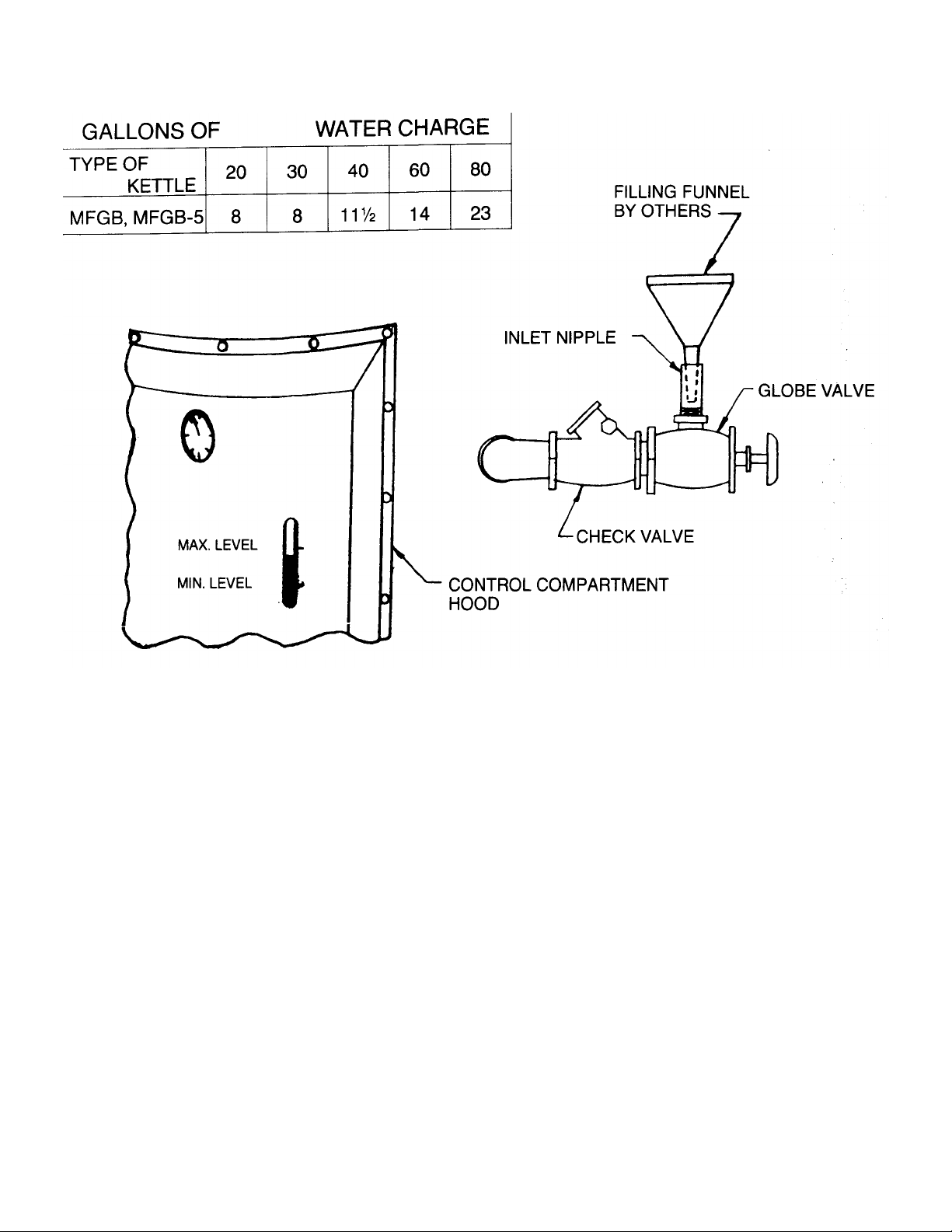
CAUTION: Steam jacket should be filled with water having a hardness no greater than 2.0 grains and
a pH between 7.0 and 8.5 only. See the above table for the quantity of water required to fill
the steam jacket to the proper level.
TO ADD WATER TO THE STEAM JACKET
1. Allow kettle to cool. Never attempt to add water to a hot kettle.
2. Lift the safety valve lever to release any residual steam contained in the steam jacket.
3. Place the thermostat in the off position. Disconnect electric power at the customer supplied
electrical cut off device.
4. Open the globe valve and place a funnel in the inlet nipple. See the above sketch.
5. Pour water into funnel. Lift safety valve lever to allow air to escape from the jacket. Continue adding
water until water in the jacket exceeds the minimum level. Do not fill above maximum level.
6. Remove the funnel, close the globe valve tightly, and restore power to the kettle.
CAUTION: Drain the steam jacket if the kettle is stored in an unheated area. Water freezing in the
steam jacket may result in permanent damage to the unit.
APPLIANCE FAILURE CAUSED BY INADEQUATE WATER QUALITY IS NOT COVERED UNDER
WARRANTY.
Page 6
INSTALLATION INSTRUCTIONS
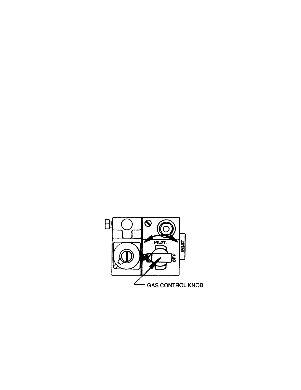
7. Burner Operating Procedure For (Standing) Pilot (MFGB MODELS)
1. Turn thermostat dial to "off".
2. Turn gas control knob on valve to "off".
3. Wait 5 minutes for gas to vent.
4. Light match. Turn gas control knob to "pilot", depress and hold down.
5. Light pilot and continue holding knob depressed for one (1) minute.
6. Release and turn knob to "on".
NOTE: If pilot does not stay on repeat Steps 1 thru 5.
7. Burner lights when thermostat is set to desired temperature.
Burner Shut Down Procedure
1. Turn thermostat dial to "off".
2. Turn gas control knob to the "pilot" position, depress slightly, and then turn to the "off" position.
GAS VALVE-MODEL MFGB
Page 7
INSTALLATION INSTRUCTIONS
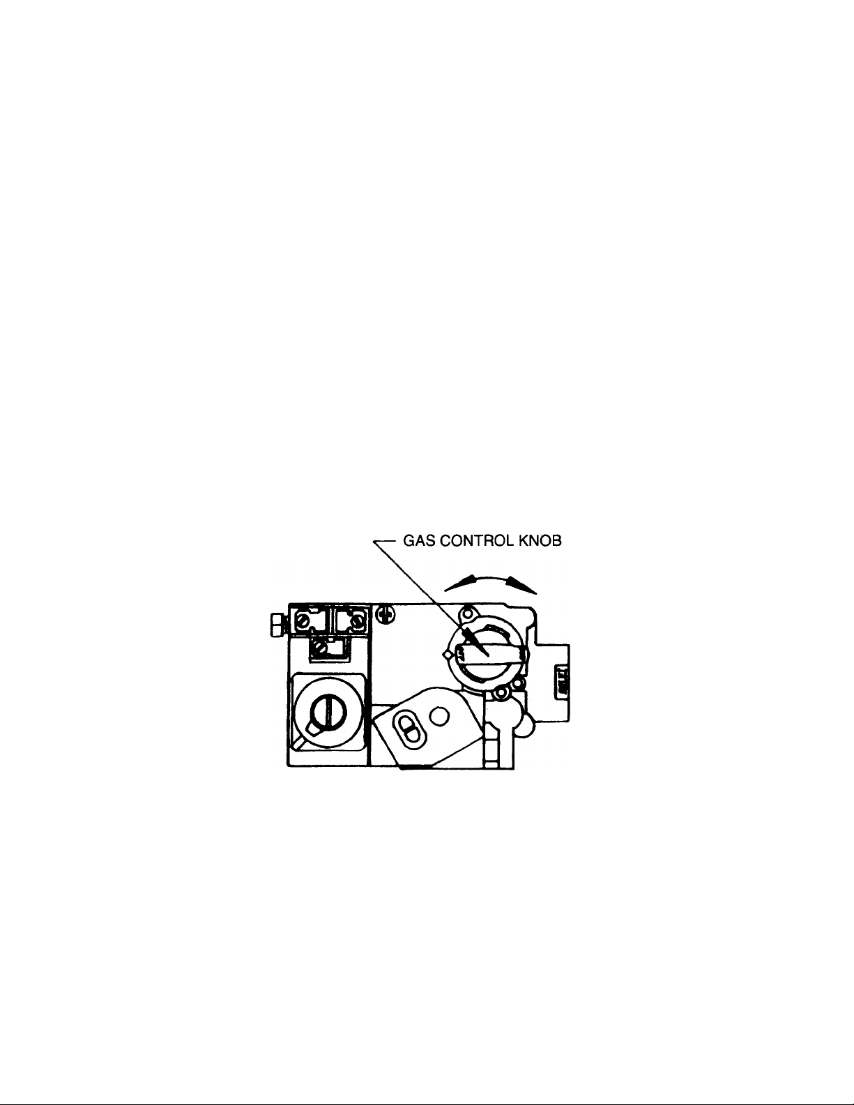
8. Burner Operating Procedure For Intermittent Pilot Spark Ignition (MFGB-5 MODELS)
CAUTION
This Kettle is equipped with Electronic Spark Ignition, DO NOT attempt to light manually.
1. Turn thermostat dial to "off".
2. Turn gas control knob to "on".
3. Burner lights when thermostat is set to desired temperature.
Burner Shut Down Procedure
1. Turn thermostat dial to "off".
2. Turn gas control knob to "off".
GAS VALVE-MODEL MFGB-5
Page 8
NOTES:
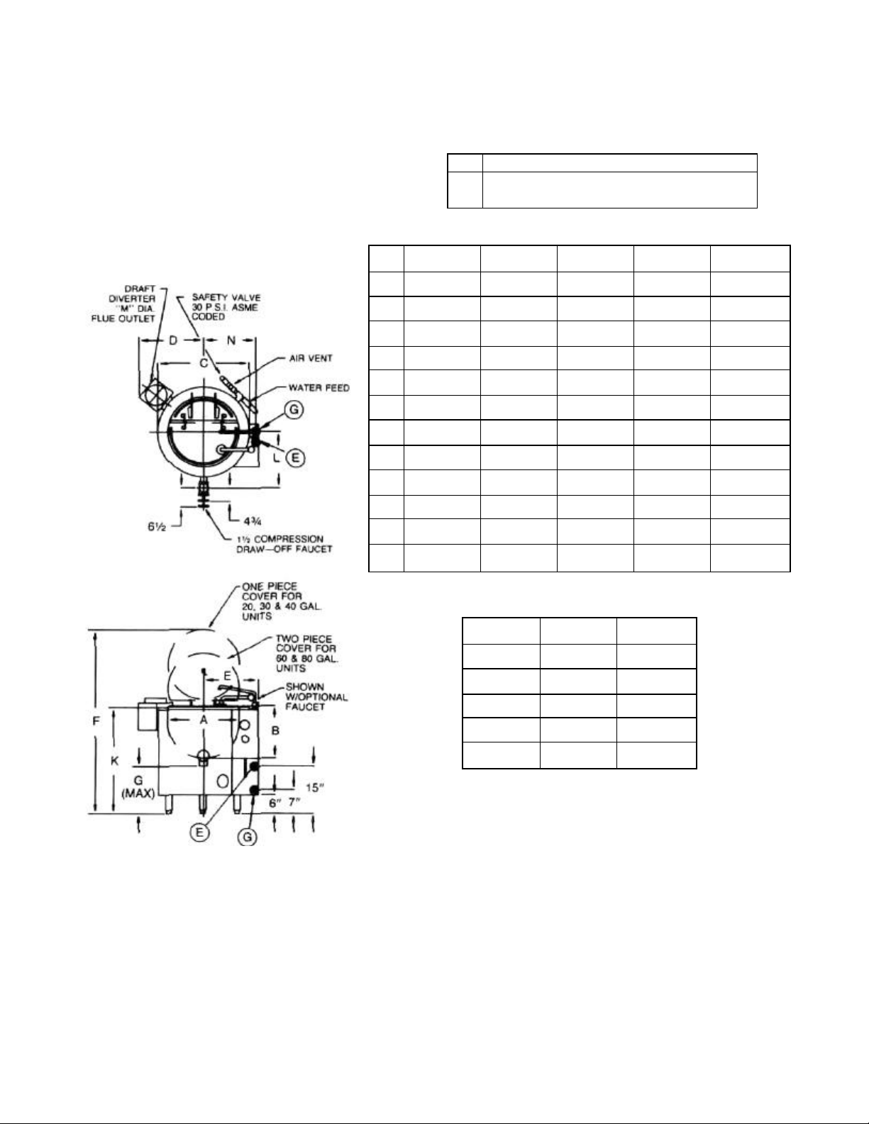
1. Clearance from combustible construction 6"
(152mm) sides and back; 2" (51mm) from flue.
2. T&S b 206 cold water 12" swing nozzle V4 N.P.T.
inlet with integral faucet —available as shown if
specified, other T&S water fill devices also
available if specified.
GAL
A 22 /559 23 /584 25 1/2 / 648 29% / 749 32 1/2 / 826
B 16 /406 20 1/4/514 22'/4/572 25 /635 27% / 702
C 28'/4/718 29 1/4/743 31 3/4/806 35% / 908 38% / 984
D 21 /533 22 /559 23 /584 25 /635 26 /660
E 17 /432 17 /432 21 /533 22 /559 23% / 597
F 56 /1422 63 /1600 66 /1676 76 /1930 82 /2083
G 15 /381 14 3/4/375 15 1/4/387 16 1/2/419 17 1/4/438
K 33% / 851 37 1/2 / 953 40 /1016 44 /1118 47 1/4/1200
L 171/4/438 17 3/4/451 19 /483 21 /533 22% / 572
M 6 /152 7 /178 7 /178 7 /178 7 /178
SERVICE CONNECTIONS Gas Fired
G
Gas Connection—1/2" (13mm) I.P.S.
Electrical Connection—115 VAC, 60Hz, single
E
phase, 1 amp. Use wire suitable for at least 90°C.
DIMENSIONS
20 30 40 60 80
IN./MM IN./MM IN./MM IN./MM IN./MM
N 1614/410 16 5/5/422 17 7/8/454 197, / 505 21 3/8/518
FIRING RATE BTU/HR
SIZE NATURAL PROPANE
20 GAL. 90,000 90,000
30 GAL. 120,000 110,000
40 GAL. 120,000 110,000
60 GAL. 125,000 125,000
80 GAL. 125,000 125,000
CAUTION:
Before connecting water to this unit, have water supply analyzed to
make sure hardness is no greater than 2.0 grains and pH level is no
greater than 7.0-8.5. Water which fails to meet these standards
should be treated by installation of a water conditioner.
EQUIPMENT FAILURE CAUSED BY INADEQUATE WATER
SUPPLY IS NOT COVERED UNDER WARRANTY.
Page 9

OPERATING INSTRUCTIONS
Daily Operation
1. Check water level in the water gauge glass. Refilling the steam jacket is seldom necessary,
however should the water level go below the minimum level, add water to the maximum level mark.
IMPORTANT: Use soft water. DISCONNECT ELECTRIC POWER.
CAUTION: NEVER ATTEMPT TO FILL KETTLE WHEN IT IS HOT.
To fill, open valve and place a funnel in the inlet nipple - add water. Remove funnel and close valve
tightly. See instructions on page 2 for filling instructions.
2. Set the thermostat dial to the desired cooking temperature, the main burner will light. The kettle will
heat the product in the cooking chamber to the pre-set temperature and automatically maintain the
temperature for an indefinite period of time.
New Temperature Setting:
If a new temperature is desired during cooking operation simply turn thermostat dial to new setting.
Should the new temperature desired be more than 60 degrees F. lower than the initial setting, it will be
necessary to wait for the kettle temperature to drop. Unit will again maintain temperature setting.
Page 10

OPERATING AND MAINTENANCE
INSTRUCTIONS
Maintenance
1. Wash kettle before and after each use with hot soapy water and rinse thoroughly with clean water.
Dry thoroughly.
2. Periodically, the main burner and the surrounding attached parts should be cleaned with a damp
cloth.
3. In the event the controls require cleaning, care must be taken to prevent moisture from settling on
the controls.
4. The stainless steel surface of the kettle may be polished with any recognized commercial stainless
steel cleaner.
5. Steel wool should not be used.
6. The safety relief valve should be tested daily when the kettle is under pressure. To test, raise lever
and discharge steam.
CAUTION: VALVE IS HOT!
If opening lever fails to discharge steam, notify service personnel at once.
7. Examine the venting system once or more a year and clean as required.
Servicing
Contact the factory at the address shown on the front of this manual, the factory representative or a
local authorized service company to perform maintenance or repairs.
Page 11

SAFETY PRECAUTIONS
THIS INSTALLATION MUST CONFORM WITH LOCAL CODES OR IN THE ABSENCE OF LOCAL CODES,
THE NATIONAL FUEL GAS CODE, ANSI Z223.1 - LATEST EDITION.
1. This appliance and its individual shutoff valve must be disconnected from the
gas supplying piping system during any pressure testing of that system at test
pressures in excess of 1/2 psig (3.45 kPa).
2. The appliance must be isolated from the gas supply piping system by closing
its individual manual shutoff valve during any pressure testing of the gas supply
piping system at test pressures equal to or less than 1/ 2 psig (3.45 kPa).
THIS UNIT MUST BE ELECTRICALLY GROUNDED IN ACCORDANCE WITH LOCAL CODES OR IN THE
ABSENCE OF LOCAL CODES, THE NATIONAL ELECTRIC CODE, ANSI/NFPA NO. 70 -LATEST EDITION.
KEEP THE AREA AROUND THE APPLIANCE FREE AND CLEAR OF COMBUSTIBLE MATERIAL.
PROVIDE ADEQUATE CLEARANCE FOR AIR OPENINGS INTO THE COMBUSTION CHAMBER. KEEP
BOXES, BAGS OR CONTAINERS CLEAR OF APPLIANCE. DO NOT OBSTRUCT THE FLOW OF AIR INTO
THE COMBUSTION CHAMBER.
ADEQUATE MAKE UP AIR MUST BE PROVIDED FOR EXHAUST SYSTEMS IN THE AREA WHERE THE
APPLIANCE IS TO BE INSTALLED.
FOR YOUR SAFETY
DO NOT STORE OR USE GASOLINE OR OTHER
FLAMMABLE VAPORS AND LIQUIDS IN THE VICINITY OF
THIS OR ANY OTHER GAS APPLIANCE.
Page 12

INTRODUCTION
Market Forge Co. gas fired kettles are widely used the world over in schools, restaurants, commissaries, cafeterias, mess halls, and wherever an external steam source is not available.
Inner kettle shells are seamless die drawn of not less than 14 GA. (.078) stainless steel.
External stainless steel jackets are fully fiberglass insulated.
Standard equipment includes a full compliment of automatic controls including an automatic air
eliminator, thermostat, floatless electronic liquid level control, combination gas valve with pressure
regulator and safety shut-off, and 30 PSI safety valve. Accessories include a 1 1/2" tangent draw-off
valve, strainer, flue diverter, compound vacuum-pressure gauge and a visible water level indicator.
All kettles are A.G.A. design certified, and constructed in compliance with A.S.M.E. code requirements
for gas fired vessels at 30 P.S.I, max. design pressure. All bear the seal of the National Sanitation
Foundation and are so listed.
Page 13

TROUBLE SHOOTING
See Corrective Maintenance for test and replacement procedures.
SYMPTOM POSSIBLE CAUSE REMEDY
NO HEAT AMBER LIGHT "ON"
NO HEAT AMBER LIGHT "OFF"
No Gas To Unit Open Manual Gas Valve
Pilot Flame Out
Thermocouple Failure Replace Thermocouple
Gas Valve Failure Replace Gas Valve
No Power To Unit Connect To Electrical Supply
Transformer Failure (220V
Option Only)
Water Level In Jacket Too Low
Scale On Low Water Probe Clean Probe
Relight (See Burner Operating
Procedure)
Replace transformer
Fill Jacket To Above Minimum Level
Mark
Thermostat Failure Replace thermostat
Pressure Switch Failure Replace Pressure Switch
Low Water Relay Failure Replace Low Water Relay
10
Page 14

CORRECTIVE MAINTENANCE
WARNING: DISCONNECT POWER BEFORE ATTEMPTING TO SERVICE THIS EQUIPMENT. DO NOT
SERVICE A KETTLE THAT IS HOT.
All controls are located inside the instrument console at the front of the kettle. They are accessed by
removing the side panel of the console. All ignition system components, except the gas valve, are
located on the ring burner beneath the kettle. See wiring diagram and electrical schematic.
Control System
The thermostat and pressure switch may be recalibrated in the field. Most electrical component
failures can be easily diagnosed by following a logical process of elimination. The pressure switch,
thermostat and primary coil on the transformer (optional) can be tested for continuity. An open circuit
indicates that the componen t has failed. The coils on the low water control relay, the secondary coil of
the transformer (optional), and the thermostat indicator light can also be tested for continuity;
however, it will be necessary to disconnect these components from the circuit before testing. Also
check the transformer for coil to coil snorting, if any control circuit components have failed.
IMPORTANT: Mark or note wiring connections before removing wires from components.
To replace the thermostat, mark and disconnect wiring terminals and remove the thermobulb from its
kettle coupling. Remove mounting screws and defective component. Install new thermobulb in kettle
coupling and mount thermostat in position. Reinstall mounting screws and replace wiring terminations.
To replace the low water control relay, pressure switch, or transformer, mark and disconnect wiring
terminals. Remove mounting screws and defective component from the console. Mount new
component in position, reinstall mounting screws, and replace wiring terminations.
Remove the low water electrode probe and visually check the porcelain insulator for cracks or scale
build up on the tip. Clean if scale is present and reinstall. Replace probe if any cracking is evident.
The low water cutoff control is a non -adjustable probe and relay type that uses the water in the steam
jacket to complete the circuit to the High Voltage secondary coil. In absence of water the relay in the
circuit drops out, cutting off the power to the gas valve.
Make sure all covers are replaced after all repairs are completed.
11
Page 15

Ignition System
The automatic continuous pilot ignition system consists of the gas valve, the pilot burner, and the
thermocouple. The thermocouple consistently monitors the flame of the pilot burner. During a call for
heat by the thermostat, the thermocou ple must sense pilot burner flame before the gas valve can open
and allow gas to the main burner. If the thermocouple fails to sense a flame the gas valve
automatically closes.
If the pilot burner ever extinguishes for any reason, relight per "Burner Operating Procedure". If the
pilot burner will not light at all, the pilot burner orifice may be clogged. It can be cleared by gently
tapping it on the side to dislodge any particles. If the pilot burner still will not light at all the gas valve is
faulty and must be replaced.
If during repeated attempts the pilot burner will not remain lit when the gas control knob is released or
goes out after a short period of time, the thermocouple is defective and must be replaced.
NOTE: In order to function properly the pilot flame should envelop % to 1/2 inch of the tip of the
thermocouple. To increase the size of the pilot flame remove the pilot adjustment cover screw
from the gas valve and turn the inner screw counter clockwise.
The pilot burner orifice is removed by unscrewing it from the pilot burner and the gas supply
tubing. The gas valve is removed by disconnecting its wires and unscrewing it from the gas
piping. The thermocouple is removed by unscrewing it from the gas valve and from the pilot
burner bracket.
12
Page 16

13
Page 17

THERMOSTAT CALIBRATION
Type
This thermostat is a snap-action, single pole, single throw cycling control, with silver contacts. Contacts
break on temperature rise and make when temperature falls below dial setting.
Rating
This control is rated for 50 volt-amperes, pilot duty 120-277 volts AC. U/L recognized for 100,000 test
cycles.
Function
The temperature sensing bulb is immersed in the pressurized steam jacket of the kettle and is
responsive to selected dial temperatures from 100° to 300°F. The food temperature in the kettle can be
correlated to the selected temperature of the steam as the active cooking medium.
Calibration
The KXP thermostat is an extremely reliable control and it is carefully calibrated at the factory. Field
recalibration is seldom necessary, and should not be resorted to unless considerable experience with
equipment proves that the control is not maintaining the temperatures to which the dial is set.
Should recalibration be required, use the following procedure:
1) Allow kettle to come to a stable temperature.
2) Turn dial and compare setting on dial with the reading of thermometer* when control turns off. (It
will make an audible click and pilot light will go off.)
3) If thermostat and thermometer agree within the users degree of accuracy , no recalibration is
necessary. If they do not agree, continue as follows.
4) Set dial to thermometer reading. Pull off dial and with a small screwdriver turn small adjusting screw
until thermostat clicks off. (Adjusting screw is in the center of the dial shaft. See drawing.)
A. CAUTION - Always use extreme care so that the slot in the center adjusting screw is not
damaged.
B. Hold dial shaft tightly while turning center screw.
* To check kettle temperatures when recalibrating, use a precision test instrument or a reliable mercury
thermometer. Place the thermocouple of test instrument or thermometer in the middle of the kettle.
14
Page 18

CONT'D
C. Turning center adjusting screw in a clockwise direction will decrease the temperature; and in a
counterclockwise direction will increase the temperature. Each quarter turn of the screw will
change the calibration approximately 30°F.
5) Recheck calibration and repeat process if closer calibration is required.
NOTES: The thermostat has an internal stop to limit the selection of temperature to 270°F.
This is required in order to prevent premature blow -off of the safety valve furnished with the
kettle. The safety valve is set at 30lbs. and has a tolerance of ±10%.
Servicing of this equipment should be referred to qualified service technicians with reputable
experience. Market Forge Co. is not responsible for any equipment serviced or installed by
non -qualified personnel.
15
Page 19

PRESSURE CONTROL ADJUSTMENT
FUNCTION:
This pressure control is used when specified, as a limit
switch in addition to the thermostatic selective cycling
control. When the limit switch is furnished on original
equipment, it is factory set to trip at bet ween 25 to 27
p.s.i. The cycling of the switch can be maintained within a
differential from 2 to 15 p.s.i.
GENERAL DESCRIPTION:
This type pressure switch is activated by the steam
pressure generated against a compression spring and a
bellow. When the sprin g compression is overcome by the
generated pressure within the bellows, the single pole,
double throw electric switch breaks the electric circuit of
the normally closed side (N.C.) of the switch, thus deenergizing the control circuit and cutting off power to the
heating elements or gas supply. As pressure drops, the
spring compression will overcome the steam pressure
within the bellow and the switch will return to its normally
closed position (N.C.) restoring current to the control
circuit.
ADJUSTMENT:
When a replacement switch is installed in the field, the
cutout and cut-in pressure setting may require calibration.
Observe pressure gauge for desired operation of the
switch. To raise both cut-in and cut-out pressure turn
slotted range adjustment screw clockwise, to decrease
turn counter-clockwise. A quarter of a turn adjustment
may change the pressure by as much as 5 p.s.i. in the 25lbs range.
To reduce the differential, turn slotted differential adjustment screw clockwise, to increase the differential turn counter-
clockwise.
Page 20

Draw-off Faucet
Various components of the draw -off faucet may be replaced. The complete draw-off
faucet may also be replaced in the field.
Safety Relief Valve
The relief valve should be manually operated at least once a day by lifting the lever and
visually verifying that steam is discharged from the valve. If steam is not discharged
remove the kettle from service immediately.
17
Page 21

In order to install a new faucet of the plug or compression type, remove all parts from
the faucet leaving only the faucet body on the draw -off tube.
1. Heat up solder joints in rear of the faucet with a blow torch until the solder starts
dripping. Tap faucet body gently from the rear while welding; use a rubber mallet or a
piece of wood and make sure the faucet is not allowed to drop.
2. After the faucet body has been removed, add acid to the draw-off tube. Heat it slightly
and add solder for retinning. Wipe off excess solder so that the draw-off tube is
completely tinned and smooth.
3. To install new faucet, likewise remove all inner parts and handles and brush acid on the
recessed seating opening in the back of the faucet and add solder. Wipe inside clean so
that the entire recessed bore is tinned. This coat of tin must be very thin and care must
be taken that neither acid nor tin find their way into the valve body.
4. Now, brush acid on the faucet and draw -off tube and slip faucet body gently onto drawoff tube making sure that the body bottoms on the draw -off tube.
5. Apply the blow torch and heat slightly all around. Add solder while heating. Very little
solder is needed. If too much solder is applied, it will enter into the valve seat region and
this must be avoided. When finished, cool water and wash clean.
6. It is helpful to tilt the kettle forward so that the draw -off tube is close to a vertical
position.
Page 22

18
Page 23

Page 24

WIRING DIAGRAM
MODEL MFGB-5
Page 25

1 97-5264
Wing Nut
6 97-5269
Stem
Item Part No. Description
2 97-5265 Heat Resistant Handle
3 97-5266 Faucet Gland
4 97-5225 Hexagon Bonnet Nut
5 97-5268 Neoprene "0" Ring
21
Page 26

Faucet Ass'y
Item Part No. Description
1 97-5229 Faucet w/12" Swing Spout
22
Page 27

Item Part No.
4
97-5235
Flue Diverter
80
Gal Kettle
Exhaust Flue Diverter
Description
1
2
3
97-5233
97-5234
97-5235
Flue Diverter 20 Gal Kettle
Flue Diverter 40 Gal Kettle
Flue Diverter 60 Gal Kettle
23
Page 28

Front Control Panel
Item Part No. Description
1 97-5208 Pressure Gauge
2
3 97-5223 Water Level Gauge Glass
97-5206
Thermostat Temp Range 100 to 300° F
24
Page 29

1 97-5243
Knob (Black)
Handle & Cover Assy.
Item Part No. Description
2
3
4
5
97-5236
97-5237
97-5238
97-5240
Cover (1) PC - 20 Gal
Cover (1) PC - 40 Gal
Cover (2) PC - 60 Gal
Cover (2) PC - 80 Gal
25
Page 30

Size
1 1/2" Draw
-
Off Faucet
Draw-Off Valve
Item Part No. Description
1 97-5225
2 97-5226 Size 2" Draw-Off Faucet
3 97-5227 Size 3" Draw-Off Faucet
26
Page 31

Item Part No. Description
1 97-5206
Thermostat Temp Range
100
to
300°
F
"
2 97-5255 Transformer Step-Down (Optional)
3 97-5207 Liquid Level Control L.W.C.O
4 97-5205 Spark Ignition Control Board (Optional)
5 97-5232
6 97-5210 Gas Control Valve (Nat'l Gas)
7 97-5210 Gas Control Valve (Propane Gas)
8 97-5211 Gas Regulator (Propane)
Right Side Control Box
Gas Cock - 1/2
27
Page 32

1 97-5220
Air Eliminator Vent
Water Fill & Safety Valves
Item Part No. Description
2 3
4 97-5230 Globe Valve
97-5221 97-5231
Safety Relief Valve (30 P.S.I.) Check Valve
28
Page 33

Combustion Chamber
1 97-5214
Burner
20
Gal.
3
4
5
6
7
8
9
10
11
Item Part No. Description
2
97-5215
97-5216
97-5216
97-5217
97-5218
97-5219
97-5219
97-5214
97-5215
97-5216
Burner 40 Gal.
Burner 60 Gal.
Burner 80 Gal.
Burner Orifice 20 Gal. (Propane)
Burner Orifice 40 Gal. (Propane)
Burner Orifice 60 Gal. (Propane)
Burner Orifice 80 Gal. (Propane)
Burner Orifice 20 Gal. (Natural)
Burner Orifice 40 Gal. (Natural)
Burner Orifice 60 Gal. (Natural)
29
 Loading...