

Page 1

MODELS:
SERVICE &
PARTS MANUAL
Manual & Automatic
2A & MF - 2A
3A & MF - 3A
Form Number 5099 6/97 Printed in U.S.A.
Page 2
Model : A-1 Cooker
Operating Instructions & General Maintenance
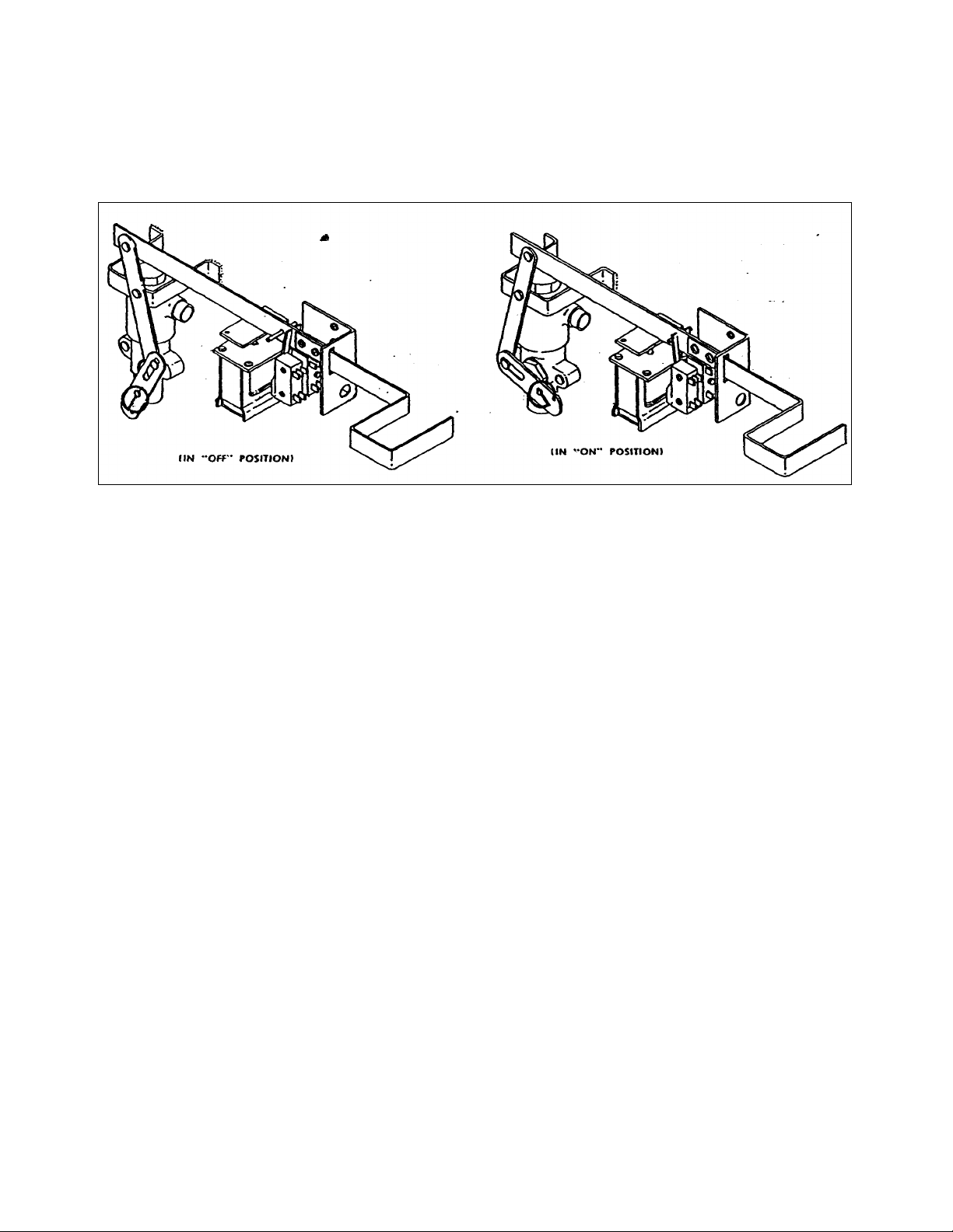
THE CONTROL BOX ASSEMBLY
The control box assembly is a device which
converts an electrical impulse into a mechanical
action. The mechanical action, stemming from
the sudden release of a spring loaded system of
levers, shuts off the steam supply, exhausts the
steam from the cooking chamber, switches off a
pilot light, and sets off a buzzer. This action is
preset manually, with the simple action of
setting the timer to the cooking timer required
and pulling out the operating handle into the
"on" position. The illustrations of "on" and "off"
positions will serve to familiarize you with the
proper relationship of the inner parts of the
control box assembly.
HOW IT WORKS
When in "off" position; the valve will be closed
re-stricting the steam from passing into the
cooking compartment, the pilot light will be off,
the buzzer inactive and the solenoid de-
energized.
When the timer is set for the required cooking
time and the operating handle is pulled to the
"on" position;
the valve will be opened to allow steam into the
cooking compartment, the pilot light will light up,
signifying that cooking is taking place, the
buzzer and solenoid will still be de-energized.
TROUBLE -TEST AND REMEDIES
If the operating handle will not lock in the "on"
When the cycle on the timer clock has been
completed, a flow of current will energize the
solenoid forcing the solenoid push rod to lift and
disengage the operating handle. The operating
handle now freed from the bumper and stop bar
will spring back to the "off" position. The innermost
micro-switch, released from the pressure of the pin
of the operating handle will break the circuit to the
solenoid, and the pilot light and the solenoid both
will become inactive. The nearer solenoid having
been pushed into a locked position under the
buzzer lock will remain in contact operating the
buzzer until re-leased by pushing the buzzer
release knob by hand.
position:
Check first that timer has been set.
Check that the stop bar is properly secured.
Check that solenoid and bracket is positioned
properly.
If the operating handle fails to retract to "off"
position:
Check the valve synchronizer spring for
looseness.
Check all linkage for binding or loosened parts.
Check switch on timer for continuity.
Check micro switch for bent arm.
Check for blown fuse and then for defective
wiring or defective solenoid.
Page 3
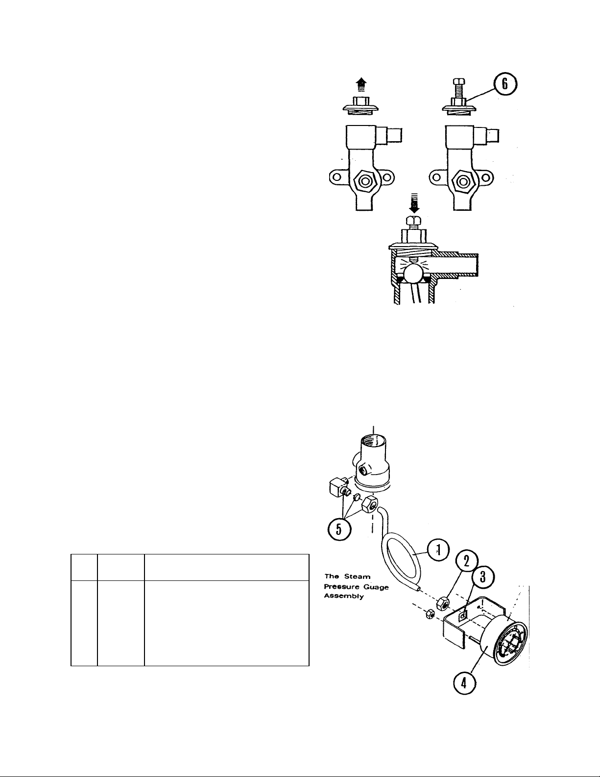
TO SERVICE SUPPLY VALVE AGAINST LEAKS
Remove the interference of the pivot arm by
detaching it at the actuating arm junction and from
the pivot stud. Remove the pivot stud and proceed
as follows:
1. Remove existing valve cap (6). (It is not
necessary to remove the valve.)
2. Replace valve cap (6) with the seating tool
after
having retarded the bolt to a point where it will not
prematurely strike the ball in the valve.
3. After the seating tool-is well secured, screw down
the bolt to make contact with the ball assembly
and apply pressure to force the ball to "make" a
new seat.
4. Remove the seating tool and replace it with
original valve cap(6). (We recommend an
application of "Rector seal" to threads to make
a secure fit.)
5. Repeat the above process if the first attempt does
not stop the valve from leaking.
*(Seating tool may be obtained from the factory.)
THE STEAM PRESSURE GAUGE ASSEMBLY
To remove the complete steam pressure gauge
assembly. it will first be necessary to remove the side
panel. The steam pressure gauge may then be
detached by removing item (2) and then removing the
two nuts which hold the pressure gauge bracket in
place. The gauge is then removed from the front of
cooker. To reassemble, reverse the above procedure.
ITEM
PART
NUMBER
1 90 - 8693 3/16" O.D. Tubing
2 10-4370 Brass Nut for Comp. Fitting
3 10-4371 Brass Sleeve for 3/16" Comp. Fitting
4 10-4748 0-30 Pressure Gauge
5 10-3360 1/8" IPS Male X3/16"O.D6 90-0018 Seating Tool
DESCRIPTION
Page 4
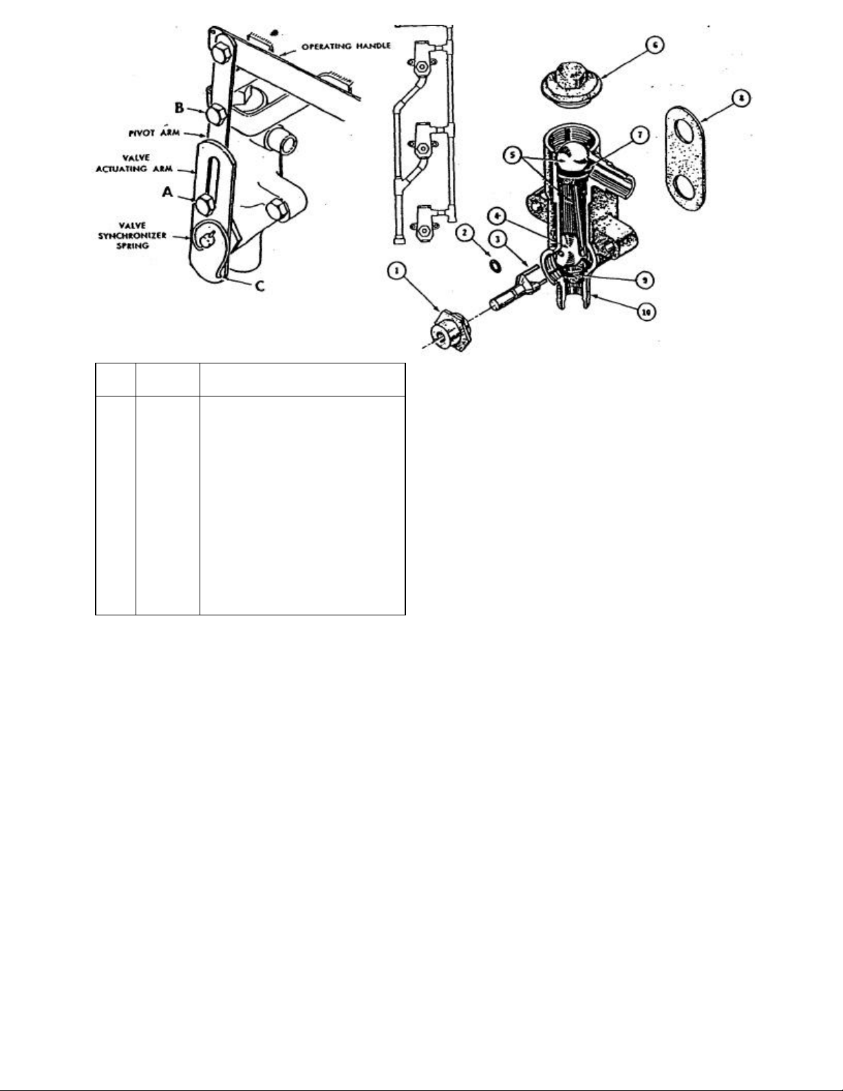
ITEM
10 90-2434 Supply & Exhaust Valve - Comp.
PART
NUMBER
1 10-3774 Valve Synchronizer Bearing
2 10-1133 'O' Ring
3 90-4153 Valve Synchronizer
4 90-0483 Exhaust Valve Ball
5 90-2419 Valve Synchronizer Lever &
6 10-0410 Valve Bonnet
7 90-2442 Supply Valve Seat
8 91-6204 Valve Body Gasket
9 90-2443 Exhaust Valve Seat
DESCRIPTION
Supply Ball Assembly
THE STEAM MANIFOLD AND VALVE
ASSEMBLY
The steam manifold and valve assembly
provides a means of steam input and exhaust
control for each cook ing compartment. Though
complete removal of the manifold and valve
assembly will be necessary to replace a
complete valve, each may be serviced in its
position by following these service instructions.
TO DISASSEMBLE VALVE
1. Shut off the steam supply to the cooker.
2. Unfasten the pivot arm at points A and B.
3. Unfasten the valve synchronizer spring at
point C remove to free valve actuating arm and
spacer.
4. Remove the pivot stud to allow more working
room.
5. Remove valve cap (6) and valve bonnet
(1).
6. Pull out valve synchronizer (3).
7. Lift out valve synchronizer lever and ball
assembly (5).
8. Insert a pencil in the hole of valve
synchronizer ball (4) and lift out through
the front portal.
TO ASSEMBLE VALVE
1. Slip valve synchronizer ball (4) into the
valve with the hole facing the front portal.
2. Drop valve synchronizer lever and ball
assembly (5) in from the top opening of
the valve with out out on the lever facing
ball (4).
3. Manipulate valve synchronizer (3) in
position (large prong in ball - smaller
prong in lever).
4. Screw on valve bonnet (1) and valve cap
(6).
5. Place the spacer over the shaft of the
valve synchronizer.
6. Place the valve actuating arm over the
shaft of the valve synchronizer with the
bushing facing the valve.
7. Fit the valve synchronizer spring into the
hole in the shaft of the valve
synchronizer, and secure it in place with
the screw and the flex -loc nut.
8. Secure the pivot stud into the wall and
assemble the pivot arm fastening at point
A and then at point 8.
Page 5

ITEM NO.
NO.
1 10-1083
Adjusting Spring
2 10-1082 Diaphragm
3 10-1075 Diaphragm Gasket
4 10-1076 Diaphragm Button & Stem
5 10-1077 Strainer
6 10-1078 Bottom Plug Gasket
7 10-1079 Bottom Spring
8 10-1080 Seat
9 10-1081 Disc Assembly
10 10-1033 3/4" Complete Valve-Painted
11 10-1034 3/4" Complete Valve-Chrome
Bottom Plug
12 10-0893 Valve Stem Guide
WATTS PRESSURE REDUCING VALVES - 3/4"
To provide adequate steam pressure regulation, your
unit may be equipped with a Watts steam pressure reducing valve. The 3/4" Watts pressure reducing valve
is designed to operate from a 7 to 50 P.S.I, source of
steam pressure and reduce this to 5 P.S.1. for delivery
to your cooker. Installation must be made from your
source of steam supply, through the pressure reducing
valve, and into the manifold input part of the steam
cooker.
Before final connection is made, blow down your
steam line to remove all dirt, scale, packing and
compound which may have accumulated during
OPERATION OF WATTS 3/4" REDUCING VALVE
Steam enters the valve at the inlet port and passes upward through the seat (8) into the discharge side of the
valve. As pressure in the discharge side increases. it
forces the diaphragm (2) upward, overcoming the
tension of the adjusting spring (1) and closing valve.
•As the pressure drops, the adjusting spring forces the
diaphragm down, reopening the valve. Where demand
and initial pressures are fairly constant, the valve
opens to the proper position and maintains the desired
reduced pressure.
PART
WARNING:
the installation of piping to the cooker.
DESCRIPTION
ADJUSTING WATTS 3/4" REDUCING VALVE
1. Release the adjusting screw lock nut and loosen
the adjusting screw enough to release all tension
on adjusting spring (1).
2. Turn steam on slowly. Then turn adjusting screw
clockwise just enough to allow the valve to open
slightly. Allow cooker to operate in this manor
several minutes.
3. Turn adjusting screw down slowly, at intervals.
until reduced pressure reaches the desired
Point. (5 P.S.1.)
4. Tighten adjusting screw lock nut.
5. If chattering noise should occur turn adjusting
screw located in bottom half of valve body.
clockwise or counter-clockwise, until chattering
stops.
INSPECTION - MAINTENANCE
Reports of unsatisfactory regulation of the pressure
reducing valve is usually due to dirt, pipe
compound. etc., blocking the internal strainer, or
gumming up the seat and disc assembly. To clean
the strainer, seat, and disc assembly remove the
bottom plug (6) and remove strainer screen (5).
bottom spring (7) and disc assy. (9) Clean the
lower part of the valve. This can be accomplished
without removing the valve from the line or
unbolting the cover. If cleaning the strainer and
disc assy. does not correct fault, the disc assy. and
seat should be replaced. Also the top cover should
be removed and the diaphragm button stem
assembly should be removed and cleaned.
REPAIRS
The following item should be cleaned or replaced
should the value fail to operate properly.
1. Both the disc assembly (9) and strainer (5) are
removed by removing the bottom plug (11) and
bottom spring (7). Upon cleaning or replacing these
items, be sure that the disc assembly (9) is seated
properly on the stem assembly (4) otherwise the
stem assembly will be bent restricting its movement
and the regulation of steam through the valve.
2. Should there be a restriction in the diaphragm button
and stem assembly (4) it will cause a drop in steam flow
or large fluctuations in steam pressure. It is then
necessary to replace diaphragm button and stem
assembly (4). valve stem guide (12) and diaphragm
gasket (3) as well as those items in step 1.
Upon completion of the above and removal of any
loose scale, which may be found in the valve, the
valve should be reassembled; and upon
installation, function properly.
Page 6

SUGGESTED STEAM CONNECTIONS
The illustration shows a recommended system of
installation which provides: a pressure gauge to
measure the pressure input at the source of supply,
a globe valve for emergency shut -off, a ball-float trap
to prevent dirt and water from entering the cooking
units, and a pres sure regulating valve to reduce and
regulate steam pres sures for delivery.
..... NOTES .....
Page 7

WIRING SCHEMATIC PARTS LIST
PER
NUMBER
1 1 10-5613
MICRO SW.
QTY.
ITEM
2 1 10-9174 RELAY, 120 VOLT
1 08-6343 RELAY. 240 VOLT
1 10-9175 SOCKET, RELAY 120 VOLT
1 08-6344 SOCKET, RELAY 240 VOLT
3 1 10-7903 TOGGLE SW.
4 1 10-5997 SOLENOID, 120 VOLT
1 10-6881 SOLENOID, 240 VOLT
5 1 10-6682 BUZZER. 120 VOLT
1 10-6665 BUZZER, 240 VOLT
1 90-9195 INSULATION, BUZZER
6 1 10-6291 60 MIN. TIMER 120 V
1 10-6293 60 MIN. TIMER 240 V
7 1 10-5499 PILOT LT. 120 V
1 10-6880 PILOT LT. 240 V
PART
DESCRIPTION
MODELS
2A - 1 AUTO. WIRING 3A - 1
PARTIAL AUTO. WIRING
NOTE: Complete schematic for 3 compartment
steamer not shown. All components are the same for 2
& 3 compartment steamers.
Page 8

MODEL A -1 DOOR ASSEMBLY
1 90-8310
MODEL A
-
1 HAND GRIP
13 10-1981
PIVOT HINGE
ITEM
10 10-3079 DOOR PIVOT BEARING 22 10-2302 HX. NUT 3/8-16
11 10-2427 1/16 THK. XI" O.D. FLAT 23 90-8317 HAND WHEEL BUSHING
12 90-8111 HINGE - POLISHED 24 10-2013 HX .JAM NUT 3/8-16
PART
NUMBER
2 10-6764 GASKET SCREWS 14 90-8328 HANDWHEEL, SPOKED
3 90-8311 GASKET PLATE 15 91-5148 OUTER DOOR. POLISHED
4 10-0433 DOOR GASKET 91-5150 OUTER DOOR. ENAMELED
5 90-8514 INNER DOOR 16 10-2423 THRUST WASHER
90-8147 INNER DOOR ASSY. (ITEMS 1 - 5 17 10-3080 DOOR BUSHING
6 10-2135 5/16 -18 X 3/4 HX. HD. BOLT 18 10-1696 ROLL PIN
7 10-2426 11/32 I.D. X 3/4 O.D. FT. WSH'R 19 90-8119 STRONG BACK
8 10-1909 5/16 THREAD SEAL 20 10-2012 CAP SCREW
9 90-8114 DOOR SPRING RELEASE 21 10-1973 SUPPORT STUD ASSY.
90-8316 HINGE - PAINTED
DESCRIPTION
ITEM
PART
NUMBER
DESCRIPTION
Page 9

SINGLE COMPARTMENT SIDE VIEW
COMP.
COMP.
ITEM
QTY.
PER
PART
NUMBER
DESCRIPTION
1 1 90-9237 ENCLOSURE, TOP - STAINLESS
1 1 90 - 9238 ENCLOSURE, TOP - PAINTED
2 1 10-6682 BUZZER, 120 VOLT
1 10-6665 BUZZER, 240 VOLT
3 1
90-9195 INSULATION, BUZZER
4 1 90 - 9188 SIDE PANEL - STN. STL ( 2 ) COMP.
1 90-9189 SIDE PANEL - ENAMEL ( 2) COMP.
1 90-9199 SIDE PANEL - STN. STL. (3) COMP.
1 90 - 9200 SIDE PANEL - ENAMEL ( 3 ) COMP.
5 1 10 - 2755 SPRING OPERATED ARM
6 1 90 - 8905 ROD, PUSH SOLENOID
7 1 90-9217 BRKT., ASSY. & MICRO SWITCH
8 1 90-8331 LATCH HANDLE ASSY.
9 1 90-9215 CONTROL HANDLE
10 1 10-5997 SOLENOID, 120 VOLT
1 10-6881 SOLENOID, 240 VOLT
11 1 10-9174 RELAY. 120 VOLT
1 08 - 6343 RELAY, 240 VOLT
12 1 10-9175 SOCKET, RELAY 120 VOLT
1 08 - 6344 SOCKET, RELAY 240 VOLT
13 1 10-2756 SYNCHRONIZER SPRING
14 1 10-3343 LOCKNUT
15 1 08-4813 STEAM TRAP ADAPTER
16 1 90-9211 ASSY, ARM OPERATING VALVE
17 1 10-6156 STEAM TRAP
18 1 10-4741 SAFETY VALVE 3/4" 8# BRASS
1 10-4742 SAFETY VALVE 3/4" 8# CHROME
ITEM
QTY.
PER
PART
NUMBER
DESCRIPTION
19 2 10 - 2403 WASHER. FLAT 1/4" STN. STL.
20 2 10 - 2508 3/8" LOCKWASHER
21 2 10-2019 MACH. TRUSS HD. 1/4 - 20 X 1/2" LG.
22 1 91-5163 LATCH, SECONDARY
23 1 91-5165 SPRING, TORSION, LATCH, SECONDARY
24 1 10-1790 HX. HD., STN. STL, 1/4 - 20 X 7/8" LG.
25 1 10-2412 WASHER. PLAIN, 3/8 ST. Nl. PLATED
26 1 95 - 3631 SPACER, 9/32 LG.
27 1 10-2508 3/8" LOCK WASHER
28 1 91-5161 HOUSING, SECONDARY, LATCH
29 1 91 - 5168 NUT, SPACER
30 A/R LOCTITE # 24205 ( AS REQUIRED )
Page 10

SINGLE COMPARTMENT SIDE VIEW
Page 11

CONTROL PANEL ASSEMBLY
2A - 1 CONTROL PANEL VIEW
3A - 1 PARTIAL CONTROL PANEL VIEW
ITEM
QTY.
PER
PART
NUMBER
DESCRIPTION
1 1 09 - 5259 KNOB. TIMER. AUTO
1 09-5270 KNOB, TIMER, MANUAL
2 1 91 - 6322 PANEL, 2-A1 60Hz. AUTO
1 91 - 6321 PANEL, 2-A1 50Hz. AUTO
1 91 - 6320 PANEL, 2-A1, MANUAL
1 91 - 6325 PANEL. 3-A1 60Hz. AUTO
1 91-6324 PANEL, 3-A1 50Hz. AUTO
1 91 - 6323 PANEL, 3-A1, MANUAL
3 1 10-4748 PRESS. GAUGE
4 1 91 - 3308 ASSY., STRAINER
5 1 10-6291 60 MIN. TIMER 120 V
1 10-6293 60 MIN. TIMER 240 V
1 10 - 5520 MANUAL TIMER
6 1 10-7903 TOGGLE SW., AUTO ONLY
7 1 10 - 5499 PILOT LIGHT, 125V
1 10-6880 PILOT LIGHT, 240V
Page 12

MODEL: A - 1 COOKER
2 2 3
2 1 1 1
3 2 2 3
4 2 2 4
5 2 2 3
6 2 2 4
7 1 1 1
8 1 1 2
9 1 1 2
10 1 1 1
11 1 1 2
12 1 1 1
13
1
14
1
15 1
16
1
17
1
ITEM
1
MODELS
2- A
QTY.
......……. ......…….
......……. ......…….
......…….
......……. ......…….
2 - A
QTY.
......……. ......…….
3 - A
QTY.
......…….
PART NUMBER
90 - 2434
10 - 3670
90 - 7100
08 - 1202
10 - 2847
10 - 4137
90 - 9985
10 - 3756
10 - 3320
90 - 8141
08 - 4913
10 - 2841
90 - 9986
10 - 3452
90 - 9970
90 - 9971
90 - 9969
HEADER ASSEMBLY SPARE PARTS LIST
DESCRIPTION
ASSEMBLY, VALVE
TEE, REDUCING, SCR. 3/4" x 1/2" x 1/2" IPS
NIPPLE, CLOSE 1/2" IPS
FITTING, HOSE NIPPLE. MALE, 1" I.D. HOSE x 3/4" NPT
NIPPLE, CLOSE 3/4"
CLAMP. HOSE DOUBLE TANG
HOSE. DRAIN 1" I.D. x 1 1/4" O.D. x 14 1/4" LG.
ELBOW, STREET 3/4" IPS
"Y"BRANCH 45 DEGREE. 3/4" IPS
REWORK, TEE
ASSEMBLY. HOSE, TEFLON W/ BRAIDED ST. STL.
ELBOW, 90 DEGREE 3/4" IPS. M.I
HOSE. DRAIN 1" I.D. x 1 1/4" O.D. x 9 3/8" LG.
TEE, 1/2" IPS
COMPLETE ASSEMBLY (ITEMS 1 -12 )
COMPLETE ASSEMBLY ( ITEMS 1 -12 )
COMPLETE ASSEMBLY ( ITEMS 1 - 14 )
 Loading...