

Market Forge M24SC Service Manual
SERVICE & PARTS MANUAL
02149
MODELS:
Modular Steam Coil Steam Supply Generators
M24SC
M36SC
Form Number S-5046A 7/84 Printed in USA
Market Forge Co.
35 Garvey Street
Everett, MA
Tel. (617) 387-4100, Telex 94-9414, Cable MAFORCO

TABLE OF CONTENTS
SECTION 1 INTRODUCTION
1.1 How to use this Manual...................…. ... 1-1
1.2 Operating Instructions for Steam Coil
Boilers..........................................……….. 1- 1
1.3 Service ..............................................……. 1-1
SECTION 2 INSTALLATION INSTRUCTIONS
2.1 Receiving Instructions.....................….. ... 2-1
2.2 Setting in place.............................. …....... 2-1
2.2.1 Installing legs.................................…..... . 2-1
2.2.2 Leveling..........................................…….. 2-1
2.2.3 Panels.............................................….... 2-1
2.3 Important information on Steam Coil Steam
Generators to Steam Fitter.................. … . 2-1
2.4 Boiler horsepower and steam flow
information .......................................…...... 2-2
2.5 Steam Fitter and plumber ................….......2-3
2.5.1 Steam Connection. .........................…...... 2-3
2.6 Setting of Steam Generator Pressure Control
Switches Units before 1979...............….... 2-4
2.7 Pressure Control Switch adjustment (Units after
1979).........................................………..... 2-5
2.8 Water Level Control (Models before Feb.
1984)................................................. .…... 2-6
2.8.1 Disassembly Instructions.................... ... 2-6
2.9 Water Level Control (Models after Feb.
1984)....................................................….. 2- 6
2.9.1 To remove Water Level Control.......…... 2-6
2.10 Watts Pressure Reducing Valves 3/4" ..... 2-7
2.10.1 Operation of Watts 3/4" Reducing
Valve...............................................…... 2- 7
2.10.2 Adjusting Watts 3/4" Reducing Valve.…… 2-7
2.10.3 Inspection , Maintenance, Repairs ..…….. 2-7
2.11 Service Connections ..........................…….. 2-8
Wiring Diagram and Schematic
SECTION 3 OPERATION
3.1 Description...........................................……... 3-1
3.2 Basic Functioning ...............................…….... 3-1
3.3 Start up Instructions............................…….... 3-2
3.3.1 Automatic Drain Steam Generator...…….... 3-2
3.3.2 Daily Operating Instructions..............……... 3-2
3.3.3 Daily Operting Instructions (For units
manufactured after June 1983, equipped with
"Momentary" heat switch)...........…………. 3-2
3.3.4 Daily Shut -down and cleaning.....……........ 3-2
3.3.5 Manual Drain Steam Generator....……....... 3-2
3.3.6 Daily Operating Instructions..........……....... 3-2
3.3.7 Daily Shut -down and cleaning.......……….... 3-2
SECTION 4 TROUBLE-SHOOTING
4.1 General.............................................……....... 4-1
4.2 Electrical Fault Isolation...................………..... 4-1
SECTION 5 ILLUSTRATED PARTS LIST
5.1 General.............................................………..... 5- 1
5.2 Ordering............................................………..... 5- 1
5.3 Index of Illustrated Parts List.............……….... 5-1
ii

Modular Steam Coil Steam Supply Generators
SECTION 1 INTRODUCTION
Market Forge, has designed these boilers with the latest type automatic controls in order to make it
easier for the operator to use and maintain this equipment. This Service and Parts Manual is written
and illustrated to cover all boiler equipment that uses a steam coil as a source of power other than
those which have been custom designed under special order.
1.1 HOW TO USE THIS MANUAL
The illustrations of components are aids to the
identification, disassembly and assembly of parts.
The part listings provide information necessary for
the ordering of replacement parts (proper part
names and part numbers). When requesting parts or
service, always furnish the model and serial number
of your complete unit, which will indicate to Market
Forge Service Division the type of boiler with which
you are equipped. This information can be found on
the nameplate attached to the boiler frame.
1.2 OPERATING INSTRUCTIONS FOR STEAM
COIL BOILERS
Explanation of how the control system works on
automatic steam coil boilers. With the boiler filled
with water to its proper level and the heat switch
turned to its on position the solenoid steam valve will
be activated allowing outside steam to flow to the
boiler steam coil. When the boiler builds up its set
pressure, the pressure switch on the left side of the
control box opens. This will open up the circuit to the
solenoid coil in the steam valve
which in turn will stop the flow of outside steam to
the boiler. As the pressure in the boiler drops off
the pressure control switch will again come into
operation and complete the circuit and build the
boiler back up to its set pressure. When the
operator wishes to stop all steam generation, he
need only place the heat switch to the off position.
1.3 SERVICE
Should repairs be required, a network of authorized
service agencies is available to assist with prompt
service. A current Directory of Authorized Service
Agencies and service assistance may be obtained
by contacting:
Product Service Department
Market Forge Company 35
Garvey Street Everett, MA 02149
Telephone: (617) 387-4100
The model and serial numbers must be referenced
when corresponding with Market Forge.
1-1

Modular Steam Coil Steam Supply Generators
SECTION 2 INSTALLATION INSTRUCTIONS
WARNING:
Read before opening the shipping
containers. Do not at any time lay the
equipment down on its back, side, top or
front. To do so may damage the equipment
and invalidate the warranty.
2.1 RECEIVING INSTRUCTIONS
Inspect the equipment before signing the bill of
lading. The equipment supplied was tested and
inspected before shipment. The carrier
accepted it as complete and without damage.
This merchandise became your property when it
was accepted by the carrier at the factory.
Market Forge cannot assume responsibility for
loss or damage during transit.
For this reason, you should immediately inspect
for visible and concealed damage or shortages
before signing for shipment as follows:
1. Count the number of cartons and packages
received to be sure they coincide with the bill
of lading.
2. Visually check all cartons for external
damage.
3. Remove all cartons from their skids to
examine equipment for concealed damage.
The carton is nailed and strapped to the skid.
It will be necessary to cut the straps and pry
off the container.
4. After inspection, replace the cartons over the
equipment on the skids to protect and secure
the equipment until it is ready for installation.
5. Sign for shipment if all is in order. Note
shortages, external and concealed damage, if
any, on the bill of lading before accepting a
partial or damaged shipment.
6. If necessary, contact the carrier immediately
to file a claim. All claims must be filed by the
receiver.
7. Do not remove the cartons or the skids from
the cooking equipment until the unit has been
transported through the building to the actual
set-up location. The cartons should remain on
the equipment as protection against dents
and scratches.
2.2 SETTING IN PLACE
2.2.1 Installing legs
Some models are shipped without legs. A
separate carton will contain the legs. If your
model is received this way be sure to follow the
installation instruction sheet packed with the
legs.
2.2.2 Leveling
In order for the boiler to drain correctly it is
important to use a level on cabinet top, both
left and right and front-to-back. If not level
adjust feet. On compartment cookers check
interior shelves to be level.
2.2.3 Panels and Doors
Panels and doors for the cabinet may be
shipped separate. Refer to installation
instructions enclosed with panels and doors
for method of attaching. It is recommended
that panels and doors be installed after
mechanical connections are made to avoid
damage.
2.3 IMPORTANT INFORMATION ON
STEAM COIL STEAM GENERATORS TO
STEAM FITTER
The use of steam coil operated equipment is
increasing, and it is important that you are
aware of both the advantages and the
limitations of this equipment.
A steam coil generator assures a supply of
clean steam, and is generally recommended
when steam is available but not considered
clean enough to come in contact with food.
Toxic steam generator cleaning compounds
are often used to clean steam generators,
and this is usually the reason for not
recommending direct -connected cookers.
It is very important that a minimum of 15 PSI
be available in the incoming steam line if a
steam coil steam generator is to be installed
for use with a 5 PSI compartment cooker. If
the equipment connected to the steam
generator operates at 15 PSI, minimum
incoming pressure must be 30 PSI, except in
the case of a single Steam-It, which can be
operated on an incoming pressure of 20 PSI.
Maximum recommended incoming steam
pressure is 50 PSI.
(Table 2-1) shows Boiler Horse Powe r (BHP)
generated by our steam coil boilers at various
incoming pressures. One (1) BHP is required
for each cooking compartment in "A" and "W"
models. A jet cooker requires 3 BHP and a
Steam-It 1/2 BHP. It is not necessary to
include steam requirements for kettles, as
kettles may be direct connected since the
steam does not come into contact with the
food.
2-1

Section
2
Installation
Pressure maintained
Steam generator Steam generator
PSI
20 PSI
PSI
.8
3.4
4.0
of Incoming Pressure)
Steam Flow in
Lbs. Steam per
1/
2
on Incoming Steam
Line
15
BHP OUTPUT
set at 15 PSI set at 5 PSI
------
3.5
15 PSI. This is because the greater the
temperature differential between the steam
on the incoming line and the steam
generated in the steam generator, the
greater the BHP available. For proper
30
35 PSI
4.0
Table 2-1
Please note that a steam coil boiler set at 5 PSI
(Maximum BHP
available regardless
cooking results you must have sufficient
steam flow. Both pressure and volume are
important.
This relates to pipe size and steam supply to
the steam coil steam generator.
will generate more boiler horsepower than one
set at
2.4 BOILER HORSEPOWER AND STEAM FLOW INFORMATION
Recommended boiler horsepower and steam flow in pounds per hour. (NOTE: 1 Boiler Horsepower 34.5 Ibs. of
steam per hour. Do not confuse steam PRESSURE with steam FLOW.)
Delivered
Boiler H.P.
Hour
Compartment steam cookers (Per compartment) 1 34.5
Steam-jacketed kettles (Per 20 gals.) 1 34.5
Direct connected Steam-It
Direct connected Jet Cooker
2 1/2
17.25
86.25
Coffee Urn (Per 10 gals.) 1/10 3.4
Steam Table (Per square ft.)
1/20
1.7
Bain Marie (Per square ft.) 1/10 3.4
Warming Oven (Per square ft.) 1/20 1.7
Table 2-2
Flow of Steam in pipe, in pounds of steam per hour.
Line pressure in lbs. per square inch (PSI) Pipe size in inches:
5 10
15 20
25 30
40 50
60 70
1/2 3/4 1 1 1/4 1 1/2 2
60
70
75
80
85
90
100
108 114
120
110 125
135 145
155 165
185 200
214 226
200 220
240 255
270 285
320 345
368 390
390 430
470 505
530 565
615 680
730 770
550 610
665 715
740 800
885 965
1030
1095
970
1075
1170
1255
1300
1400
1550
1680
1800
1910
Table 2-3
2-2
Modular Steam Coil Steam Supply Generators
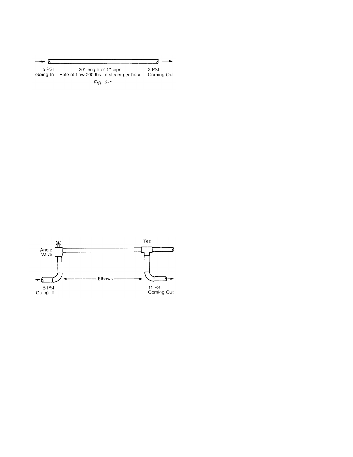
Capacities are based on allowing a pressure drop of 2
245
Actual run
20'.
Equivalent run
41.4'.
Rate of
PSI in a length of pipe equal to 240 diameters of the
pipe. For ex ample, (Fig. 2-1) in one-inch pipe, at the
steam flows shown, there would be a pressure drop of
2 PSI in 240 inches, (20 feet) of straight run.
If the rate of flow is increased, the pressure drop will
be greater. If the rate of flow is decreased, the
pressure drop will be less.
Elbows, valves, and other fittings cause greater
pressure drop. (See next section)
In determining proper pipe size at a given line
pressure to deliver the desired rate of steam flow and
pressure at the steam cooker, it is necessary to know
not only the actual length of the pipe run, but also the
equivalent length of run. Each fitting or value causes
resistance equal to a certain length of straight pipe.
This equivalent length must be added to the actual
length in order to determine the equivalent length of
run. For example, (Fig. 2-2) assume an actual length
of 20' of 20" pipe with two elbows, an angle valve, and
a side outlet tee. Table 2-4 shows that to determine
the equivalent length of run we must add 2.2' for each
of the elbows , 12' for the angle valve, and 5' for the
side outlet tee, giving us an equivalent length of run of
41.4' of straight pipe.
Resistance of fittings expressed in terms of equivalent length of straight pipe. (Measurements are in
feet)
Pipe
Standard
Size
Elbow
1.3' 3' .3' 14' 7'
1/2"
3/4" 1.8' 4' .4' 18' 10'
1" 2.2' 5' .5' 23' 12'
1
3.0' 6' .6' 29' 15'
1
3.5' 7' .8' 34' 18'
2" 4.3' 8' 1' 46' 22'
Side
Outlet
Tee
Gate
Valve
Globe
Valve
Table 2-5
Temperature (degrees F) of steam at various
altitudes and pressures.
Altitude 5 PSI 10 PSI 15 PSI
Sea level
2000 feet
5000 feet
10,000 feet
227
224
220
213
240
237
234
228
Table 2-4
Rule-of-thumb Conversion Information
• 1 BHP —approximately 10 KW
• 1 BHP —approximately 34,000 BTU
These conversions are easily-remembered
approximations. In making conversions, the
efficiency of the steam generator must be
considered. A gas steam generator with an input of
34,000 BTU and operating at 50% efficiency, will
deliver 1/2 BHP.
Angle
Valve
250
248
240
Flow: 240 Ibs. of steam per hour.
Fig. 2-2
2-3
2.5 STEAM FITTER AND PLUMBER
2.5.1 Steam Connection
It is recommended that, whenever possible, the
steam input to the steam generator be a separate
line from the source of supply. If the steam
generator must be piped to a line which also
supplies other steam consuming devices, the pipe
sizes and pressures will have to be verified as to
capacity.
Section
2
Installation
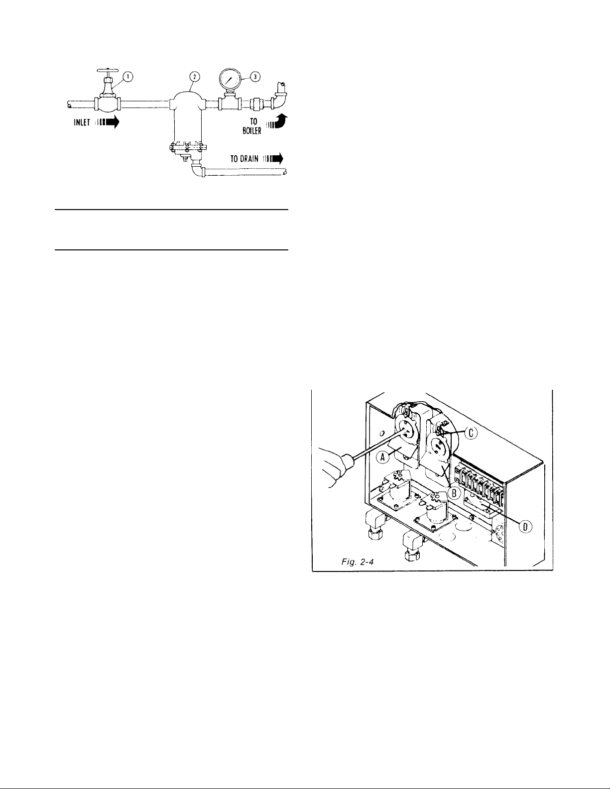
SUGGESTED STEAM CONNECTIONS:
ITEM
1
2
3
Fig. 2-3
(Fig. 2-3) shows a recommended system of the
installation which includes the following equipment: A
globe valve for shut off, a ball float trap which assures
that the steam supply is clean and dry, a pressure
gauge to measure inlet pressures from the source of
supply.
DESCRIPTION
3/4" Globe Valve
Ball Float Trap
Pressure Gauge
PART NO.
10-2821
10-5336
NOTE: If steam supply line has an extremely high
excess amount of condensate, it may be neces sary to
install 2 ball float traps.
10% of recommended operating pressure, the
pressure control switches are adjusted properly and
the unit is operating satisfactorily.
4. Steam generator pressure switches are factory set
and should not be adjusted unless absolutely
necessary. If pressure is found to be other than
above, proceed as follows:
a. Remove front cover from modular control
box.
b. With screwdriver adjust pressure switches (A) and
(B). Steam coil steam generators used to
generated steam for a Steam-It, Jet Steam
Cooker or Kettle which operate at 15 PSI should
be set as follows: Switch (A) should be set at 12
PSI and Switch (B) at 20 PSI. If 15 Ib. steam
generator is used for 5 Ib. operation, follow
above instructions and then refer to "adjusting
watts 3/4" pressure reducing valve".
c. Steam coil steam generators used to generate
steam for a compartment type steam cooker
which operates at 5 PSI should be set as follows:
Switch (A) should be set at 5 PSI and Switch (B)
at 10 PSI. d. Dial C is the differential dial and
should always be set at 1 PSI on both Switch (A)
and (B).
e. The cold water condenser thermostat (Dial D) is
provided as standard equipment with all
automatic drain steam generators. This
thermostat is preset at the factory for 140°F and
should not be re-adjusted in the field.
IMPORTANT
Before making final connection, blow out the steam
line to remove all dirt, scale, packing, etc., that may
be accumulated during pipe fittings.
If condensate coming out of the coil is to be returned
to the customer's steam generator, disconnect the
condensate tubing from the main drain and connect it
to the optional condensate return fitting. See page 2-8
for location of this connection.
2.6 SETTING OF STEAM GENERATOR PRESSURE CONTROL SWITCHES (On models
before 1979) (Fig. 2-4)
To be sure steam generator pressure control
switches are set properly, use the following
procedure:
1. Start steam generator and allow it to build up to
pressure- 5 Ibs. or 15 Ibs.
2. Release pressure into cooking chamber by turning
on unit- Jet, Compartment Cooker, Steam-It.
3. Shut off cooking unit and let steam generator build
back up to pressure. Check the steam generator
pressure gauge. If pressure is within
2-4
NOTE: On earlier model steam generators,
adjustments of the pressure control switches may be
done with a screwdriver as shown. Later model steam
generators require the use of a special wrench, which
may be obtained from Market Forge.
Modular Steam Coil Steam Supply Generators
2.7 PRESSURE CONTROL SWITCH ADJUSTMENT (On models after 1979) (Fig. 2-5) If
generator fails to maintain steam pressure in
operating range, pressure control switch may
require adjustment.
1. Start generator and allow pressure to build up
to operating level -15 PSI 1 kg/cm2.
2. Check generator pressure gauge. If gauge
indicates 12 to 14 PSI, pressure control
switches are properly adjusted.
3. If generator does not come on when pressure
gauge reads 12 PSI and does not go off when
pressure gauge reads 14 PSI, proceed as
follows:
a. Remove screws and lift front cover off
control box.
Warning: Because power must be on to
adjust pressure switches, be sure to
protect against electrical shock.
b. Hand adjust operating pressure control
switch (A) and high limit pressure control
switch (B) by turning adjusting nut (Knurled
knob) clockwise to raise and counter-
Fig. 2-5
clockwise to lower actuation point. Switch
(A) should be set so that generator comes
on when generator pressure gauge reads
12 PSI and goes off when gauge reads 14
PSI. Switch (B) should be set so that
generator will shut off if pressure reaches
15 PSI. If 15 Ib. steam generator is used for
5 Ib. operation, follow above instructions
and then refer to "adjusting watts 3/4"
pressure reducing valve".
c. The actuation value (differential) is factory
set and cannot be changed.
d. The cold water condenser thermostat is
pre-set at factory at 130°F 54° C and
should not be reset.
e. Repeat steps 1, 2, and 3. If 12 to 14 PSI
generator pressure gauge reading is
obtained during generator operation,
adjustment is correct. If proper adjustment
cannot be made, consult Trouble-Shooting
Guide in Section 4, in this manual.
f. After making adjustments, replace cover on
control box.
2-5
Section
2
Installation
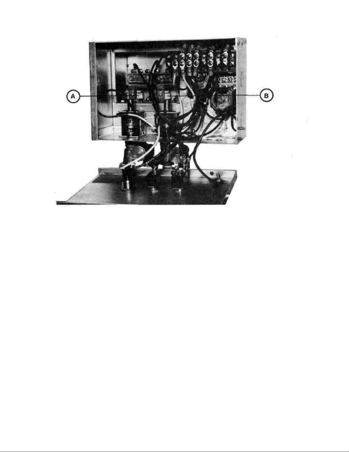
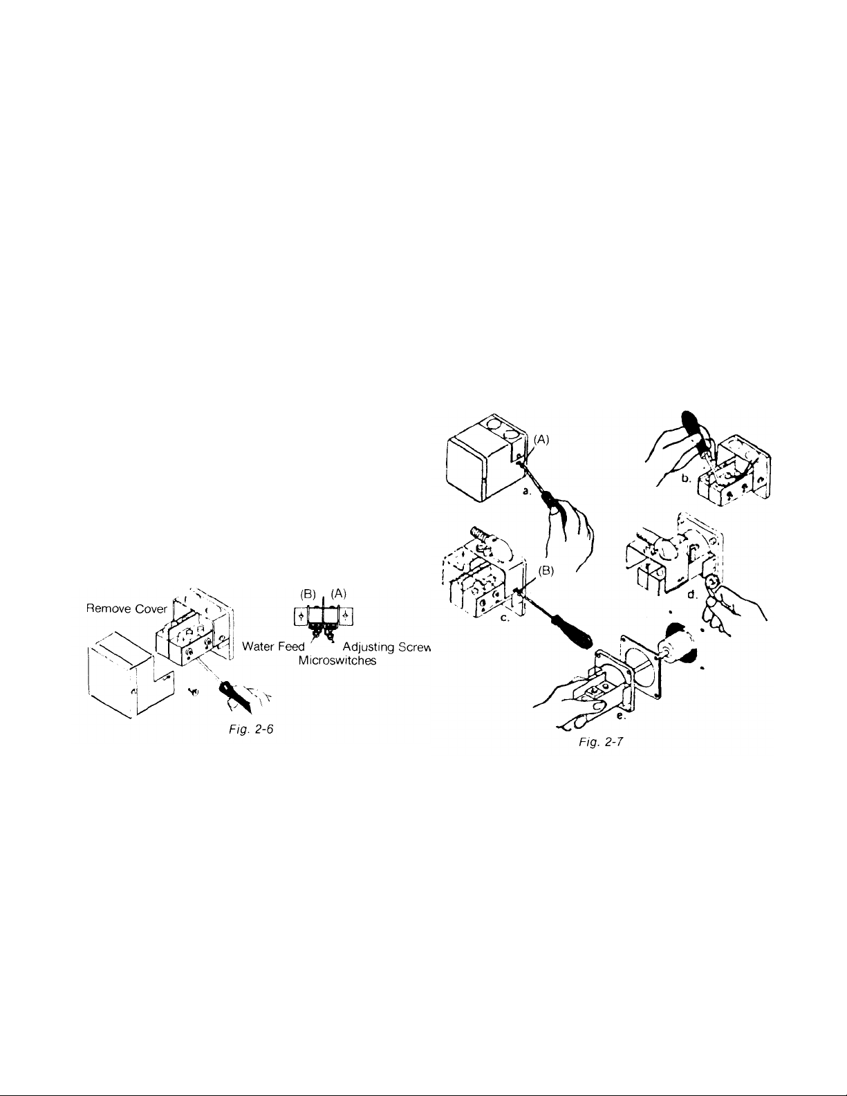
2.8 WATER LEVEL CONTROL (On models
before Feb. 1984)
The Water Level Control used by Market Forge is a
float type switch with a float ball inside the boiler. The
water level control is equipped with two microswitches
which turn the water supply on and off and the power
supply on and off. (Fig. 2-6)
Microswitch (A) prevents the source of power from
coming on until there is an adequate supply of water
in the boiler.
Microswitch (B) shuts off water supply when the water
level has reac hed 2/3 full as viewed in the gauge
glass.
CAUTION:
Before removing cover disconnect 115V power
supply. When the boiler is full, water level should
reach 2/3 full in gauge glass and the water feed
should shut off. If this is not correct, remove cover to
water level control and adjust Microswitch (B). To
adjust, loosen lock nut and turn screw clockwise to
raise level and counterclockwise to lower level.
If no water is visible in gauge glass and power comes
on when water switch is reset, this indicates that:
1. Microswitch (A) is out adjustment and must be
readjusted. To adjust, remove cover to water level
control, loosen lock nut and turn adjusting screw in
a clockwise direction. Continue this adjustment so
that heat does not come on until the gauge glass is
2/3 filled with water.
2. Use Ohmmeter across to check for proper
continuity through microswitches.
c. Remove the two screws (B) on either side of
housing. The housing, with all external wiring still
attached, may then be removed to one side.
d. With an Alien set screw wrench remove the set
screws at the four corners of the mounting plate.
e. Pull ouy and remove the complete float assembly
and gasket from the boiler.
f. Clean the internal boiler parts of the water level
control. Use a tooth brush to clean the bellows. If
the deposits are excessive, a flat blade putty knife
may be used to clear accumilations from between
the bellows fins. However, care should be used
not to rupture them or twist bellows out of
alignment. When satisfied that the complete float
switch assembly is clean, and that the bellows are
free to operate properly, reinstall assembly into the
boiler using a new gasket to establish a firm seal.
First, be sure that surfaces contacting the gasket
are completely clean. Reverse the disassembly
steps to reinstall into the boiler.
g. CAUTION: Be sure to check adjustments as shown.
2.8.1 Disassembly Instructions
Remove water level control as follows: (Fig. 2-7)
a. Remove the two screws (A) on either side and
remove the cover.
b. Disconnect the 4 intial wires from their
terminals. Mark all wires and terminal posts to
simplify reassembly.
2-6
2.9 WATER LEVEL CONTROL (On models
after Feb. 1984)
CAUTION:
Before removing cover, disconnect power
supply.
The McDonnell-Miller Water Level Control is not
adjustable. If not functioning properly, entire water
level control must be replaced.
 Loading...