

Page 1

MODULAR
5033A
Printed in U.S.A.
4/75
Everett Ma.
02149
GAS
STEAM
SUPPLY
GENERATORS
Parts & Service
Manual
Area Code 617 387-4100
Page 2

TABLE OF CONTENTS
5035
Subject Code No. Page
HOW TO USE THIS MANUAL 5023 3
BOILER STARTING INSTRUCTIONS 5023 3
170,000 BTU GAS BOILER - ASSEMBLY 5024 4
170 000 BTU GAS BOILER -PARTS LIST 5024 4
250,000 BTU GAS BOILER - ASSEMBLY 5026 5
250,000 BTU GAS BOILER - PARTS LIST 5026 5
LIGHTING INSTRUCTIONS 5028 6
ADJUSTING THE BURNERS 5028 6
CONTROL BOX ASSEMBLY - MANUAL BLOWDOWN 5150 7
CONTROL BOX.ASSEMBLY - AUTOMATIC BLOWDOWN 5151 8
WATER LEVEL CONTROL 5008 9
WATER LEVEL CONTROL ADJUSTMENTS 5009 10
SERVICING THE SOLENOID WATER FEEDERS 5009 10
PRESSURE REDUCING VALVE 5010 11
24 INCH CABINET 5011 12
36 INCH CABINET 5012 13
WIRING DIAGRAMS 5013 14
WIRING DIAGRAMS 5014 15
TROUBLE -SHOOTING GUIDE 5029 16
TROUBLE -SHOOTING GUIDE 5030 17
TROUBLE -SHOOTING GUIDE 5031 18
SETTING OF BOILER CONTROL PRESSURE SWITCHES 5032 19
COLD WATER CONDENSER ADJUSTMENT 5032 19
Page 3

HOW TO USE THIS MANUAL
Market Forge, in the interest of both costs and efficiency to the purchasers of its equipment,
has designed these boilers with the latest type automatic controls in order to make it easier
for the operator to use and maintain this equipment. In addition, standard components are
utilized on all models of boiler equipment unless variances in size or capacity dictate a
divergence from this policy for more efficiency in operation. This parts and service manual is
written and illustrated to cover all boiler equipment that uses gas as a source of power other
than those which have been custom designed under special order.
The exploded view drawings of components are aids to the identification, disassembly and
assembly of parts. The parts listings provide information necessary for the ordering of
replacement parts (proper part names and part numbers). When requesting parts or service,
always furnish the model and serial number of your complete unit, which will indicate to
Market Forge Service Division the type of boiler with which you are equipped. This information
can be found on the nameplate attached to the boiler frame.
OPERATING INSTRUCTIONS FOR GAS BOILERS
Explanation of how the control system works on manual and automatic gas boilers. With the
boiler filled with water to its proper level and the fuel switch turned to its on position, the
solenoid in the gas valve will be activated allowing gas to flow to main burner which will be
ignited by the pilot. When the boiler builds up to its se t pressure, the pressure switch on the
left side of the control box opens. This will open up the circuit to the solenoid coil in the gas
valve which, in turn, will stop the flow of main gas to the burners. As the pressure in the
boiler drops off the pressure control switch will again come into operation and complete the
circuit and build the boiler back up to its set pressure. When the operator wishes to stop all
generation he need only to place the fuel switch to the off position.
5023
Page 4
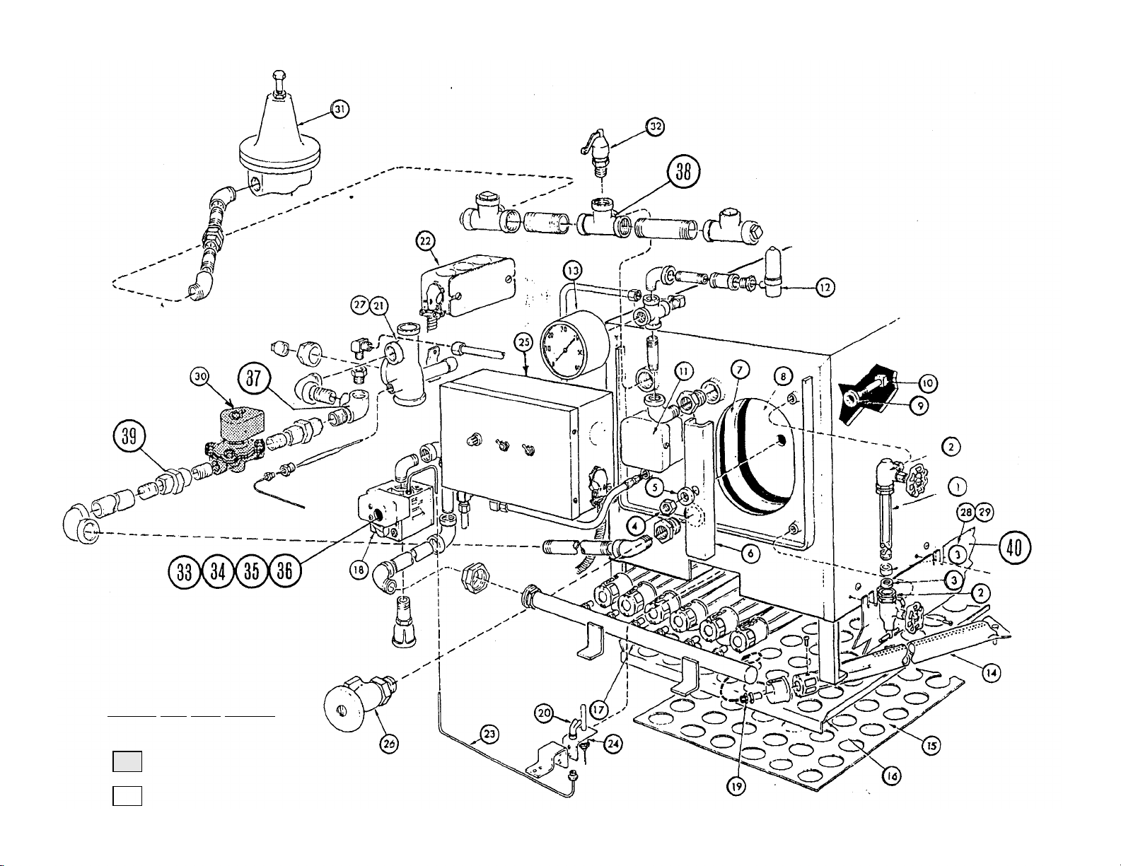
170,000 BTU GAS BOILER
AUTOMATIC BOILERS ONLY
30
SUPPLIED WHEN BOTH 5
&15STEAM SUPPLY IS NEEDED
Page 5
McDONNELL MILLER
P
ROBE SYSTEM
MODEL: M24G1A or M36G1A
SPARE PARTS LIST GAS STEAM GENERATORS
170,000 BTU'S
ITEM QTY. PART NUMBER DESCRIPTION
1 1 10-1146 WATER GAUGE GLASS 51/2"
1 10-5869 WATER GAUGE GLASS 11"
2 1 10-4940 WATER GAUGE ASSY.
3 1 90 - 0039 RUBBER & BRASS WASHERS
4 1 10-2310 5/8" HEX NUT ( hand hole cover)
5 1 10-2414 5/8" WASHER ( hand hole cover )
6 1 90 - 5492 CHANNEL, YOKE ( hand hole cover )
7 1 10-2661 HAND HOLE GASKET
8 1 90 - 5495 HAND HOLE COVER
9 1 10-1135 DYNA - SEAL WASHER
10 1 10-2118 BOLT ( hand hole cover)
WATER LEVEL CONTROL ASSEMBLIES
WATTS
11 1 90 - 8929 COMPLETE FLOAT ASSEMBLY
2 10-5714 MICRO SWITCHES
1 10-5208 FLOAT BALL
1 10-5209 GASKET
1 90 - 5249 HEAD BELLOWS LINK & ROD ASSY.
1 91 - 5382 KIT, ADAPTOR - GASKETS
1 91 - 6222 HEAVY DUTY GASKET KIT
11 1 09 - 4887 REWORKED FLOAT ASSEMBLY
1 08-1409 GASKET, RING
8 09 - 3436 HX. HD.SCW.10-24 x 1/2" lg.
11 1 91 - 6287 KIT, FIELD REPLACEMENT, PROBES, PLATE & GASKET
1 91 -5112 KIT, FIELD REPLACEMENT, (3) PROBES, PLATE & GASKET
1 08 - 6328 LIQUID LEVEL CONTROL BD. ( 120 volt
1 08 - 6329 LIQUID LEVEL CONTROL BD. ( 240 volt)
1 08 - 6407 LIQUID LEVEL CONTROL BD. ( California Code )
1 08 - 6364 LIQUID LEVEL PROBE ( water fill )
1 08 - 6365 LIQUID LEVEL PROBE (low water level )
1 91 - 6286 PROBE PLATE, WELDED
1 08 - 4405 GASKET FOR PROBE PLATE
1 91 - 7031 PROBE PLATE, WELDED, ( 3 ) PROBES
1 08-4413 GASKET FOR PROBE PLATE # 91 - 7031
1 08 - 6398 LIQUID LEVEL PROBE, PRIMARY ( low water level )
1 08 - 6399 LIQUID LEVEL PROBE, SECONDARY ( low water level)
2 10-2515 LOCKWASHER, HELI - SPRING
2 10-8353 RUBBER BOOT FOR PROBES
4 09 - 3436 HX. HD. SCW. 10 - 24 x 1/2" lg.
12 1 10-4556 AIR VENT
13 1 10-4804 PRESSURE GAUGE
14 7 10-3250 BURNER
15 1 90 - 9429 LOWER DEFLECTOR PLATE ASSY.
16 1 90 - 9428 UPPER DEFLECTOR PLATE ASSY.
17 1 10-1043 GAS MANIFOLD
18 1 10-6472 GAS VALVE ( 120volt) NATURAL 3/4" inlet X 3/4" outlet
1 10-7683 GAS VALVE ( 120volt) PROPANE 3/4" inlet X 3/4" outlet
1 10-7684 GAS VALVE ( 240volt) NATURAL 3/4" inlet X 3/4" outlet
1 10-7685 GAS VALVE ( 240volt) PROPANE 3/4" inlet X 3/4" outlet
1 10-6465 GAS VALVE ( 120volt) NATURAL 1/2" inlet X 3/4" outlet
Page 6

1 91-1337 DESCALER
MODEL: M24G1A or M36G1A
SPARE PARTS LIST GAS STEAM GENERATORS 170,000
BTU'S
ITEM QTY. PART NUMBER DESCRIPTION
1 10-6487 ADAPTER PLATE FOR PROPANE
19 7 10-2916 BURNER ORIFICE ( all btu's ) NATURAL
7 10-2921 BURNER ORIFICE ( all btu's ) PROPANE
20 1 10-5253 PILOT BURNER & ORIFICE ( natural )
1 10-5254 PILOT BURNER & ORIFICE ( propane )
1 91 -6154 PILOT BRACKET
21 1 90-1724 2" DRAIN LINE ASSY., AUTOMATIC
1 90-1832 2" DRAIN LINE ASSY., MANUAL OBSOLETE - NLA
22 1 10-5163 HAND BOX
23 1 95 - 3880 PILOT BURNER GAS LINE 24"
1 90 - 7948 PILOT BURNER GAS LINE 36"
24 1 10-6048 THERMOCOUPLE
25 1 90 - 5295 CONTROL BOX ASSY., MANUAL
1 90 - 5294 CONTROL BOX ASSY., AUTOMATIC
26 1 10-3661 DRAIN VALVE STD.
27 1 90-1724 2" DRAIN LINE ASSY., AUTOMATIC
1 90-1728 2" DRAIN LINE ASSY., AUTOMATIC
28 1 90 - 2823 SIDE COVER PLATES RIGHT & LEFT
29 1 90 - 2822 REAR COVER PLATES
30 1 10 -5787 1/2" SOLENOID ASCO DRAIN VALVE
1 10-1311 3/4" DRAIN VALVE
1 08 - 4872 COIL ONLY; FOR 3/4" DRAIN VALVE
1 10-3015 DRAIN VALVE REPAIR KIT ( new style )
31 1 10-1033 PRESSURE REDUCING VALVE
32 1 10-7955 15# SAFETY VALVE
1 10-4741 8# SAFETY VALVE ( 5# boilers only )
GAS VALVE - EXTENSION FOR PILOT PART NUMBERS
33 1 10-6467 ROD ADAPTER
34 1 10-1662 COTTER PIN
35 1 99-1310 GAS CONTROL KNOB
36 1 99-1313 EXTENSION ROD
MISCELLANEOUS
37 1 10-3489 3/4" 90 DEGREE OUTLET ELBOW
38 1 10-3490 3/4" 4 WAY TEE
39 1 10-2844 3/4" UNION
INSULATION
40 2 10-4095 MARONITE, SIDE INSULATION
BOILER SHELL, FLUE PARTS & MISELLANEOUS
1 90 - 9404 BOILER REPLACEMENT SHELL
1 90 - 9323 INNER FLUE
1 90 - 8849 OUTER FLUE ( RIGHT SIDE )
1 90 - 8850 OUTER FLUE ( LEFT SIDE )
1 90-1811 ACCEPTOR FOR FLUE
1 10-0880 GAS SOLENOID VALVE (120volt)
Page 7
Page 8
MODEL: M36G2A
WATER LEVEL CONTROL ASSEMBLIES
11 1 09 - 4887
REWORKED FLOAT ASSEMBLY
SPARE PARTS LIST GAS STEAM GENERATORS
250,000 BTU'S
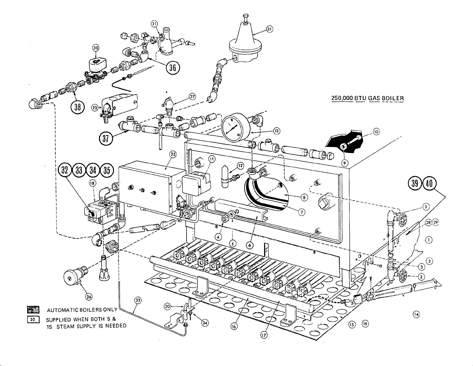
ITEM QTY. PART NUMBER DESCRIPTION
1 1 10-4754 WATER GAUGE GLASS 6"
1 10-5869 WATER GAUGE GLASS 11"
2 1 10-4576 WATER GAUGE ASSY.
3 1 90 - 0039 RUBBER & BRASS WASHERS
4 1 10-2310 5/8" HEX NUT ( hand hole cover )
5 1 10-2414 5/8" WASHER ( hand hole cover )
6 1 90 - 5492 CHANNEL, YOKE ( hand hole cover )
7 1 10-2661 HAND HOLE GASKET
8 1 90 - 5495 HAND HOLE COVER
9 1 10-1135 DYNA - SEAL WASHER
10 1 10-2118 BOLT ( hand hole cover)
WATTS
11 1 90 - 8929 COMPLETE FLOAT ASSEMBLY
2 10-5714 MICRO SWITCHES
1 10-5208 FLOAT BALL
1 10-5209 GASKET
1 90 - 5249 HEAD BELLOWS LINK & ROD ASSY.
1 91 - 5382 KIT, ADAPTOR - GASKETS
1 91 - 6222 HEAVY DUTY GASKET KIT
McDONNELL MILLER
1 08-1409 GASKET, RING
8 09 - 3436 HX. HD.SCW.10-24 x 1/2" Ig.
PROBE SYSTEM
11 1 91 - 6287 KIT, FIELD REPLACEMENT, PROBES, PLATE & GASKET
1 91 -5112 KIT, FIELD REPLACEMENT, (3) PROBES, PLATE & GASKET
1 08 - 6328 LIQUID LEVEL CONTROL BD. (120 volt)
1 08 - 6329 LIQUID LEVEL CONTROL BD. ( 240 volt)
1 08 - 6407 LIQUID LEVEL CONTROL BD. ( California Code )
1 08 - 6364 LIQUID LEVEL PROBE ( water fill )
1 08 - 6365 LIQUID LEVEL PROBE (low water level)
1 91 - 6286 PROBE PLATE, WELDED
1 08 - 4405 GASKET FOR PROBE PLATE
1 91 - 7031 PROBE PLATE, WELDED, ( 3 ) PROBES
1 08-4413 GASKET FOR PROBE PLATE # 91 - 7031
1 08 - 6398 LIQUID LEVEL PROBE, PRIMARY (low water level )
1 08 - 6399 LIQUID LEVEL PROBE, SECONDARY (low water level)
2 10-2515 LOCKWASHER, HELI - SPRING
2 10-8353 RUBBER BOOT FOR PROBES
4 09 - 3436 HX. HD. SCW. 10 - 24 x 1/2" Ig.
12 1 10-4556 AIR VENT
13 1 10-4804 PRESSURE GAUGE
14 7 10-2940 BURNER
15 1 90 - 2830 LOWER DEFLECTOR PLATE ASSY.
16 1 90 - 2829 UPPER DEFLECTOR PLATE ASSY.
17 1 10-1060 GAS MANIFOLD
Page 9
PARTS THAT ARE NOT SHOWN
MODEL: M36G2A
SPARE PARTS LIST GAS STEAM GENERATORS
250,000 BTU'S
ITEM QTY. PART NUMBER DESCRIPTION
18 1 10-6472 GAS VALVE ( 120volt) NATURAL 3/4" inlet X 3/4" outlet
1 10 -7683 GAS VALVE ( 120volt) PROPANE 3/4" inlet X 3/4" outlet
1 10 -7684 GAS VALVE ( 240volt) NATURAL 3/4" inlet X 3/4" outlet
1 10-7685 GAS VALVE ( 240volt) PROPANE 3/4" inlet X 3/4" outlet
1 10-6465 GAS VALVE ( 120volt) NATURAL 1/2" inlet X 3/4" outlet
19 7 10-2916 BURNER ORIFICE ( all btu's ) NATURAL
7 10-2921 BURNER ORIFICE ( all btu's ) PROPANE
20 1 10-5253 PILOT BURNER & ORIFICE ( natural )
1 10-5254 PILOT BURNER & ORIFICE ( propane )
1 91 - 3696 PILOT BRACKET
21 1 90-1724 2" DRAIN LINE ASSY., AUTOMATIC
1 90-1834 2" DRAIN LINE ASSY., MANUAL
22 1 10 -5163 HAND BOX
23 1 90 - 7888 PILOT BURNER GAS LINE
24 1 10-6048 THERMOCOUPLE
25 1 90 - 5295 CONTROL BOX ASSY., MANUAL
1 90 - 5294 CONTROL BOX ASSY., AUTOMATIC
26 1 10-3661 DRAIN VALVE STD.
27 1 10-7955 15# SAFETY VALVE
1 10-4741 8# SAFETY VALVE ( 5# boilers only )
28 1 90 - 2823 SIDE COVER PLATES RIGHT & LEFT
29 1 90 - 2822 REAR COVER PLATES
30 1 10-5787 1/2" SOLENOID ASCO DRAIN VALVE
1 10-1311 3/4" DRAIN VALVE
1 08 - 4872 COIL ONLY; 3/4" DRAIN VALVE
1 10 -3015 DRAIN VALVE REPAIR KIT ( new style )
31 1 10-1033 PRESSURE REDUCING VALVE
GAS VALVE - EXTENSION FOR PILOT PART NUMBERS
32 1 10-6467 ROD ADAPTER
33 1 10-1662 COTTER PIN
34 1 99-1310 GAS CONTROL KNOB
35 1 99-1313 EXTENSION ROD
MISCELLANEOUS
36 1 10-3489 3/4" 90 DEGREE OUTLET ELBOW
37 1 10-3490 3/4" 4 WAY TEE
38 1 10-2844 3/4" UNION
INSULATION
39 2 10 -4065 MARONITE, SIDE INSULATION
40 1 10-4068 MARONITE, REAR INSULATION
BOILER SHELL, FLUE PARTS & MISELLANEOUS
1 90-2817 BOILER REPLACEMENT SHELL
1 90 - 4525 INNER FLUE
1 90 - 8849 OUTER FLUE ( RIGHT SIDE )
1 90 - 8850 OUTER FLUE ( LEFT SIDE )
1 90 - 8066 ACCEPTOR FOR FLUE
1 91-1337 DESCALER
Page 10

LIGHTING INSTRUCTIONS FOR MANUAL GAS BOILER
WITH MANUAL RESET (PILOT AND BURNERS)
1
2
3
ADJUSTING
5028 t
I. Turn gas valve to OFF. Depress knob and turn clockwise;
wait 5 minutes for unburned gas to vent.
While this is taking place, close boiler drain valve, open
boiler inlet valve- flip water switch from Blowdown to On.
3. While boiler is filling, light match or taper.
4 Gas valve knob must be Fully and Continuously Depressed
during this entire step:
a. Depress knob and hold depressed while turning
counter clockwise from Off to pilot and then —
b. Continue Holding Knob Depressed while lighting
pilot and about one minute longer to allow pilot
to heat.
5 Release knob. If pilot goes out when knob is released,
return knob to Off and repeat steps 1, 3, and 4.
6. Then turn gas valve knob counter clockwise until it snaps
into the final stop at On.
IMPORTANT: Knob will automatically return in Pilot
if not snapped all the way to the On position.
7. When boiler is filled it is necessary to manually reset the.
unit by flipping water switch from on to Blowdown and
back to On immediately. .Had- light will come on.
8. Flip fuel switch from Off to On (This will bring gas
burners on.)
The boiler has been adjusted and tested to operate with the type of gas indicated on the nameplate. However, as the nature of gas will
THE
BURNERS
SEE LIGHTING INSTRUCTIONS AND PROCEED TO
LIGHT BOILER
Look at the flame on each burner and open or close the air
shutters of each to establish the best possible adjustment.
See the chart which shows typical flame characteristics for
each type of gas.
The orifice is factory set to the correct position, if proper
adjustments cannot be made in step No. 2
Refer to the chart on Page 6 which shows the
proper water column pressure for the type of
gas used. Take a water column measurement
at the removable plug in the center of the gas
manifold.
sometimes vary in another location, minor adjustments may have to be made to establish the most efficient burner flame. In cases
where manufactured or mixed gases are to be used, these adjustments will have to be made. To adjust:
ORIFICE DRILL SIZE
NATURAL GAS PROPANE GAS
170= No. 42
250 = No. 44
WATER COLUMN
AT MANIFOLD
TOO MUCH AlR
LIGHTING INSTRUCTIONS FOR AUTOMATIC GAS BOILE \
With MANUAL RESET - (PILOT AND BURNERS)
1. Turn gas valve to OFF. (Depress knob and turn clockwise.)
Wait 5 minutes for unburned gas to vent.
2. While this is taking place, flip Water switch from Blowdown
to On. Wait 3 minutes for Water to fill in boiler.
3. While boiler is filling, light match or taper.
4. Gas valve knob must be fully and continuously depressed
during this entire step:
a. Depress knob and hold expressed while turning)
counterclockwise from Off to Pilot and then b. Continue holding knob depressed while lighting
pilot and about one minute longer to allow pilot
to heat.
5. Release knob. If Pilot goes out when knob is released,
return knob to Off and repeat steps 1, 3, and 4.
6. Then turn gas valve knob counterclockwise until it snaps
into the final stop at On.
IMPORTANT: Knob will automatically return to Pilot
if not snapped all the way to the On. position.
7. When boiler is filled it is necessary to manually reset the
unit by flipping Water switch from On to BIowdown and
back to On immediately. Red light will come on.
8. Flip Fuel switch from Off to On. (This will bring gas
burners on).
A. IF PRESSURE IS LOW:
Check your gas supply line for a restriction of some nature. If
no restriction exists, check with your gas supplier to provide at
least 4" of water column pressure in the gas supply line. If no
restriction exists and bottled gas is being used, the tank pressure
regulator should be adjusted to supply at least 11" of water
column at the burner manifold. If this adjustment cannot be
made to satisfaction, the gas supplier should be notified.
B. IF PRESSURE IS TOO HIGH:
Adjust the gas regulator on the gas valve to cut down the pres
sure if natural gas is being used. If bottled gas is being used,
adjust gas regulator supplied by gas supplier. If it cannot be
adjusted, notify gas supplier.
170= No. 54
250 = No. 52
3 ½” 11"
IDEAL FLAME
NOT ENOUGH
AIR
Page 11

MODEL: M24G1A or M36G1A
1 1 10-1146
WATER GAUGE GLASS
51/2"
WATER LEVEL CONTROL ASSEMBLIES
WATTS
11 1
90 - 8929
COMPLETE FLOAT ASSEMBLY
McDONNELL MILLER
11 1
09 - 4887 :
REWORKED FLO
AT ASSEMBLY
PROBE SYSTEM
11 1
91 - 6287
KIT. FIELD REPLACEMENT. PROBES, PLATE
&
GASKET
SPARE PARTS LIST GAS STEAM GENERATORS 170,000
BTU'S
ITEM QTY. PART NUMBER DESCRIPTION
1 10-5869 WATER GAUGE GLASS 11"
2 1 10-4940 WATER GAUGE ASSY.
3 1 90 - 0039 RUBBER & BRASS WASHERS
4 1 10-2310 5/8" HEX NUT (hand hole cover)
5 1 10-2414 5/8" WASHER (hand hole cover)
6 1 90 - 5492 CHANNEL, YOKE (hand hole cover)
7 1 10-2661 HAND HOLE GASKET
8 1 90 - 5495 HAND HOLE COVER
9 1 10-1135 DYNA - SEAL WASHER
10 1 10-2118 BOLT (hand hole cover)
2 10-5714 . MICRO SWITCHES
1 10-5208 FLOAT BALL
1 10-5209 GASKET
1 90 - 5249 HEAD BELLOWS LINK & ROD ASSY.
1 08-1409 GASKET, RING
8 09 - 3436 HX. HD. SCW. 10 - 24 x 1/2" lg.( LWCO plate (4) req'd)
1 .08-6328 LIQUID LEVEL CONTROL BD. (120 volt)
1 08 - 6329 . LIQUID LEVEL CONTROL BD. ( 240 volt)
1 08 - 6407 LIQUID LEVEL CONTROL BD. ( California Code )
1 08 - 6364 LIQUID LEVEL PROBE ( water fill)
1 08 - 6365 LIQUID LEVEL PROBE (low water level)
1 91 - 6286 PROBE PLATE, WELDED
1 • 08 - 4405 GASKET FOR PROBE PLATE
2 10-2515 LOCKWASHER, HELI - SPRING
2 10-8353 RUBBER BOOT FOR PROBES
4 09 - 3436 HX. HD. SCW. 10 - 24 x 1/2" lg.( LWCO plate (4) req'd)
12 1 10-4556 AIR VENT
13 1 10-4804 PRESSURE GAUGE
14 7 10-3250 BURNER
15 1 90 - 9429 LOWER DEFLECTOR PLATE ASSY.
16 1 90 - 9428 UPPER DEFLECTOR PLATE ASSY.
17 1 10-1043 GAS MANIFOLD
18 1 10-6472 GAS VALVE (120volt) NATURAL
1 10-7683 GAS VALVE (120volt) PROPANE
1 10-7684 GAS VALVE ( 240volt ) NATURAL
1 10-7685 GAS VALVE ( 240volt) PROPANE
1 10-6487 ADAPTER PLATE FOR PROPANE
M-G1A1.XLS
Page 12

MODEL: M24G1A or M36G1A
33 1 10-6467
ROD ADAPTER
37 1 10-
3489
3/4" 90
DEGREE OUTLET ELBOW
40 2 10-4095
MARONITE, SIDE INSULATION
1 90 - 9323
INNER FLUE
ITEM QTY. PART NUMBER DESCRIPTION
19 7 10-2916 BURNER ORIFICE ( all btu's ) NATURAL
7 10-2921 BURNER ORIFICE ( all btu's ) PROPANE
20 1 10-5253 PILOT BURNER & ORIFICE ( natural)
1 10-5254 PILOT BURNER & ORIFICE ( propane )
1 91 -6154 PILOT BRACKET
21 1 90-1724 2" DRAIN LINE ASSY., AUTOMATIC
1 90-1832 2" DRAIN LINE ASSY., MANUAL OBSOLETE - NLA
22 1 10-5163 HAND BOX
23 1 95 - 3880 PILOT BURNER GAS LINE 24"
1 90 - 7948 PILOT BURNER GAS LINE 36"
24 1 10-6048 THERMOCOUPLE
25 1 90 - 5295 CONTROL BOX ASSY., MANUAL
1 90 - 5294 CONTROL BOX ASSY., AUTOMATIC
26 1 10-3661 DRAIN VALVE STD.
27 1 90-1724 2" DRAIN LINE ASSY., AUTOMATIC
1 90-1728 2" DRAIN LINE ASSY., AUTOMATIC
28 1 90 - 2823 SIDE COVER PLATES RIGHT & LEFT
29 1 90 - 2822 REAR COVER PLATES
30 1 10-5787 1/2" SOLENOID ASCO DRAIN VALVE
1 10-1311 3/4" DRAIN VALVE
1 08 - 4872 COIL ONLY; FOR 3/4" DRAIN VALVE
1 10-3015 DRAIN VALVE REPAIR KIT (new style )
31 1 10-1033 PRESSURE REDUCING VALVE
32 1 10-5320 15# SAFETY VALVE
1 10-4741 8# SAFETY VALVE ( 5# boilers only )
GAS VALVE - EXTENSION FOR PILOT PART NUMBERS
34 1 10-1662 COTTER PIN
35 1 99-1310 GAS CONTROL KNOB
36 1 99-1313 EXTENSION ROD
MISCELLANEOUS
38 1 ' 10-3490 3/4" 4 WAY TEE
39 1 10-2844 3/4" UNION
INSULATION
PARTS THAT ARE NOT SHOWN
FLUE PARTS & MISELLANEOUS
1 90 - 8849 OUTER FLUE ( RIGHT SIDE )
1 90 - 8850 OUTER FLUE ( LEFT SIDE )
1 90-1811 ACCEPTOR FOR FLUE
1 91 -1337 DESCALER
M-G1A1.XLS
Page 13

AUTOMATIC BOILERS ONLY
250,000 BTU GAS BOILER
SUPPLIED WHEN BOTH 5&
30
15 STEAM SUPPLY IS NEEDED
Page 14

MODEL: M36G2A
1 1 10-4754
WATER GAUGE GLASS
6"
W
ATER LEVEL CONTROL ASSEMBLIES
WATTS
11 1
90 - 8929
COMPLETE FLOAT ASSEMBLY
McDONNELL M
ILLER
11 1 09 - 4887
REWORKED FLOAT ASSEMBLY
PROBE SYSTEM
11 1
91 - 6287
KIT, FIELD REPLACEMENT, PR
OBES, PLATE
&
GASKET
1
2 1 10-4556
AIR VENT
SPARE PARTS LIST GAS STEAM GENERATORS 250.000
BTU'S
ITEM QTY. PART NUMBER DESCRIPTION
1 10-5869 WATER GAUGE GLASS 11"
2 1 10-4576 WATER GAUGE ASSY.
3 1 90-0039 RUBBER & BRASS WASHERS
4 1 10-2310 5/8" HEX NUT ( hand hole cover )
5 1 10-2414 5/8" WASHER ( hand hole cover )
6 1 90 - 5492 CHANNEL, YOKE ( hand hole cover )
7 1 10-2661 HAND HOLE GASKET
8 1 90 - 5495 HAND HOLE COVER
9 1 10-1135 DYNA - SEAL WASHER
10 1 10-2118 BOLT ( hand hole cover)
2 10-5714 MICRO SWITCHES
1 10-5208 FLOAT BALL
1 10-5209 GASKET
1 90 - 5249 HEAD BELLOWS LINK & ROD ASSY.
1 91 - 5382 KIT, ADAPTOR - GASKETS
1 91 - 6222 HEAVY DUTY GASKET KIT
1 081409 GASKET, RING
8 09 - 3436 HX. HD. SCW. 10 - 24 x 1/2" lg.( LWCO plate (4) req'd)
1 08-6328 LIQUID LEVEL CONTROL BD. ( 120 volt)
1 08 - 6329 LIQUID LEVEL CONTROL BD. ( 240 volt)
1 08 - 6407 LIQUID LEVEL CONTROL BD. ( California Code )
1 08 • 6364 LIQUID LEVEL PROBE ( water fill)
1 08 - 6365 LIQUID LEV EL PROBE (low water level)
1 91 - 6286 PROBE PLATE, WELDED
1 08 - 4405 GASKET FOR PROBE PLATE
2 10-2515 LOCKWASHER, HELI - SPRING
2 10-8353 RUBBER BOOT FOR PROBES
4 09 - 3436 HX. HD. SCW. 10 - 24 x 1/2" lg.( LWCO plate (4) req'd)
13 1 10-4804 PRESSURE GAUGE
14 7 10-2940 BURNER
15 1 90 - 2830 LOWER DEFLECTOR PLATE ASSY.
16 1 90 - 2829 UPPER DEFLECTOR PLATE ASSY.
17 1 10-1060 GAS MANIFOLD
18 1 10-6472 GAS VALVE ( 120volt ) NATURAL
1 10-7683 GAS VALVE (120volt) PROPANE
M-G2A1 .XLS
Page 15

MODEL: M36G2A
32 1 10-6467
ROD ADAPTER
36 1 10-3489
3/4" 90
DEGREE OUTLET ELBOW
39 2 10-4065
MARONITE. SIDE INSULATION
ITEM QTY.
1 10-7684 GAS VALVE ( 240volt ) NATURAL
1 10-7685 GAS VALVE ( 240volt) PROPANE
19 7 10-2916 BURNER ORIFICE ( all btu's ) NATURAL
7 10-2921 BURNER ORIFICE ( all btu's ) PROPANE
20 1 10-5253 PILOT BURNER & ORIFICE ( natural )
1 10-5254 PILOT BURNER & ORIFICE ( propane )
1 91 - 3696 PILOT BRACKET
21 1 90-1724 2" DRAIN LINE ASSY., AUTOMATIC
1 90-1834 2" DRAIN LINE ASSY., MANUAL
22 1 10-5163 HAND BOX
23 1 90 - 7888 PILOT BURNER GAS LINE
24 1 10-6048 THERMOCOUPLE
25 1 90-5295 CONTROL BOX ASSY., MANUAL
1 90 - 5294 CONTROL BOX ASSY., AUTOMATIC
26 1 10-3661 DRAIN VALVE STD.
27 1 10-5320 15# SAFETY VALVE
1 10-4741 8# SAFETY VALVE ( 5# boilers only )
28 1 90 - 2823 SIDE COVER PLATES RIGHT & LEFT
29 1 90 - 2822 REAR COVER PLATES
30 1 10-5787 1/2" SOLENOID ASCO DRAIN VALVE
1 10-1311 3/4" DRAIN VALVE
1 08 - 4872 COIL ONLY; 3/4" DRAIN VALVE
1 10-3015 DRAIN VALVE REPAIR KIT ( new style )
31 1 10-1033 PRESSURE REDUCING VALVE
GAS V ALVE - EXTENSION FOR PILOT PART NUMBERS
PART NUMBER DESCRIPTION
33 1 10-1662 COTTER PIN
34 1 99-1310 GAS CONTROL KNOB
35 1 99-1313 EXTENSION ROD
MISCELLANEOUS
37 1 10-3490 3/4" 4 WAY TEE
38 1 10-2844 3/4" UNION
INSULATION
40 1 10-4068 MARONITE, REAR INSULATION
PARTS THAT ARE NOT SHOWN
FLUE PARTS & MISELLANEOUS
1 90 - 4525 INNER FLUE
1 90 - 8849 OUTER FLUE ( RIGHT SIDE )
1 90 - 8850 OUTER FLUE ( LEFT SIDE )
1 90 - 8066 ACCEPTOR FOR FLUE
1 91-1337 DESCALER
M-G2A1 .XLS
Page 16

Market Forge Industries
35 GARVEY STREET, EVERETT, MA 02149
CONTROL BOX ASSEMBLY
Page 17

Market Forge Industries
CONTROL BOX ASSEMBLY
35 GARVEY STREET, EVERETT, MA 02149
ITEM QTY.
1 1 90 - 9299 BOX, CONTROL - ALL BOILERS
2 1 10-6008 ASSY. PRES. CONTROL SWITCHES - OBSOLETE TO 91 - 5139
2A 1 10-8410 PRESSURE SWITCH ( high limit)
2B 1 10-8411 PRESSURE SWITCH ( operating pressure^)
3 1 10 -4653 THERMOSTAT ( drain condensate )
4 1 10-4634 TIME DELAY RELAY ( 120 volt)
5 1 10-6512 RELAY SOCKET
6 2 10-1326 HAYS SOL. VALVE ( 120 VOLT ) ( USED ON OLDER MODELS )
PART
NUMBER
DESCRIPTION
7 2 10 - 1330 REMOVABLE STRAINER FOR HAYS VALVE
8 1 10-6169 PILOT LIGHT
9 1 10-5008 HEAT SWITCH D.P.D.T. ( OLDER MODELS WITH WATTS FLOAT )
40 1 10-5022 ON - OFF SWITCH S.P.S.T.
11 1 10-5184 TERMINAL STRIP
12
13
14
15 1 91 - 8703 CONTROL BOX ASSY. (120 VOLT W / AUTO DRAIN )
2 10-0865 HAYS SOL. VALVE ( 240 VOLT ) ( USED ON OLDER MODELS )
2 08 - 4821 SKINNER VALVE (120 VOLT ) CURRENT MODELS
2 08-4810 SKINNER VALVE ( 240 VOLT ) CURRENT MODELS
2 06 - 4871 REMOVABLE STRAINER FOR SKINNER VALVE
1 10-5484 HEAT SWITCH D.P.D.T. ( momentary ) CURRENT MODELS
1 91 - 8704 CONTROL BOX ASSY. ( 240 VOLT W / AUTO DRAIN ) EXPORT
1 91 - 8705 CONTROL BOX ASSY. ( 120 VOLT W / MANUAL DRAIN )
1 91 - 8706 CONTROL BOX ASSY. ( 240 VOLT W / MANUAL DRAIN ) EXPORT
1 91 - 8701 C - BOX ASSY. ( 120 VOLT W / AUTO DR. ) A - PLUS W / KETTLE
1 91 - 8702 C - BOX ASSY. ( 240 VOLT W / AUTO DR. ) A - PLUS W / KETTLE
10-1329 REPLACEMENT COIL FOR PART NUMBER 10 - 1326
10-4035 DOLE SOLENOID VALVE (120 VOLT)
10-1109 STRAINER FOR DOLE VALVE
Page 18

CONTROL BOX ASSEMBLY
MANUAL RESET- MANUAL BLOW-DOWN -AUTOMATIC WATER FEEDER
MODULAUR UNIT
ITEM NO. PART NO. DESCRIPTION
1 90-9299 Control Box
2 10-6008 Assy. Pres. Control switches
for manual reset boiler
3 10-5184 Terminal Strip
4 10-4634 Relay
5 10-6512 Octal Socket
6 10-1 326 Hays Solenoid Valve
90-5284 Hays Valve Replacement Kit
ITEM NO. PART NO. DESCRIPTION
7 10-5008 Switch - Double pole - Double throw
8 10-5022 Switch - Single pole - Single throw
9 10-4982 Dialco Pilot light assembly
10 10-1330 Strainer for Hays Valve
11 101329 120 Volt Coil for Hays Valve
12 10 4035 Dole Solenoid Valve*
13 10-1109 Strainer for Dole Valve*
14 90-5295 Complete Control Box Assembly
* These parts are no longer used on the unit.
5150
Page 19

Replacement Parts
Water Level Control
ITEM DESCRIPTION PART NO.
1 Complete m/f low water cut off 90-8929
2 M/F low water cut off conv. 90-9808 Jet Only
3 Head bellows link & Rod Assy. 90-5249
4 Gasket 10-5209
5 Float Ball 10-5208
6 Nylon Adjusting Screw 10-0135
and Nut 10-0136
7 Center Insulator 90-5222
8 Micro Switch 10-5714
5008
Page 20

WATER LEVEL CONTROL
Each boiler was operated and tested before it left our factory.
However, due to vibration in transit or variations in altitude,
some of the controls may need re-adjusting.
The Water Level Control used by Market Forge is a float type
switch with a float ball inside the boiler. The water level
control is equipped with two micro-switches which turns the
water supply on and off and the power supply on and off.
Microswitch A prevents the source of power from coming on
until there is an adequate supply of water in the boiler.
Microswitch B shuts off the water supply when the water level
is approximately 2/3 from the top of the sight glass.
WATER LEVEL
When the boiler is full, water level should be 2/3 from the top
of sight gauge and the water feed should shut off. If this is not
correct, remove cover to water level control and adjust
Microswitch B. CAUTION - Before removing cover disconnect
HOW TO CLEAN THE DOLE SOLENOID WATER
FEEDERS IN THE MODULAR CONTROL BOX
If water level does not shut off at the required 2/3 full in sight
glass and Microswitch B is set correctly, this indicates that
sediment has become lodged on seat of solenoid water
feeder keeping valve in open position.
To Service:
A. Flush down boiler
B. Shut off water supply
C. Shut off main power
D. Remove front cover from modular control box
E. Break tubing connections at bottom of solenoid
valves (A)
110V power supply. To
adjust, loosen lock nut and turn screw clockwise to raise level
and counter clockwise to lower level.
If no water is visible in gauge glass and power comes on
when water switch is reset, this indicates that:
1. The float of the water level control has become
detached during transit. Shut off power, open hand
hole door and re-install float ball.
2. Or that microswitch A is out of adjustment and must be
re-adjusted. To adjust remove cover to water level
control and loosen lock nut and turn adjusting screw in
a clockwise direction. Continue this adjustment so that
fuel does not come on until the sight glass :., 2/3 filled
with water.
CAUTION: Before removing cover disconnect 110V power
supply.
F. Remove (4) four screws inside control box to remove
bottom of control box (B). It is not necessary to
remove the complete box.
G. Disconnect wires (1), (2), and (3) from solenoid coils
(wires are marked).
H. To remove coil remove right rear screw (C) from
solenoid valve.
I To remove valve to clean the seat or to replace,
remove remaining (3) three screw (D).
J. Reassemble or replace valve by reversing steps j-a.
When replacing coil be sure that quick disconnects
face front ofr'modular control box. Also arrow on
valve should face front of control box.
5009
Page 21

ADJUSTING WATTS 3/4" REDUCING VALVE
1. Release the adjusting screw lock nut and loosen the adjusting
screw enough to release all tension on adjusting spring (1).
2. Turn steam on slowly. Then turn adjusting screw clockwise
just enough to allow the valve to open slightly. Allow cooker
to operate in this manor several minutes.
3. Turn adjusting screw down slowly, at intervals, until
reduced pressure reaches the desired Point. (5 P.S.I.)
4. Tighten adjusting screw lock nut.
5. If chattering noise should occur turn adjusting screw located
in bottom half of valve body, clockwise or
counter-clockwise, uniti chattering stops.
Replacement Parts For
Type W ¾ Pressure Reducing
Valve
ITEM NO. PART NO. DESCRIPTION
1 10-1083 Adjusting Spring
2 10-1082 Diaphragm
3 10-1075 Diaphragm Gasket
4 10-1076 Diaphragm Button & Stem Assembly
5 10-1077 Strainer
6 10-1078 Bottom Plug Gasket
7 10-1079 Bottom Spring
8 10-1080 Seat
9 10-1081 Disc Assembly
10 10-1033 3/4" Complete Valve-Painted
11 10-1034 3/4" Complete Valve-Chrome
Bottom Plug
12 10-0893 Valve Stem Guide
WATTS PRESSURE REDUCING VALVES - 3/4"
To provide adequate steam pressure regulation, your unit may be
equipped with a Watts steam pressure reducing valve. The 3/4"
Watts pressure reducing valve is designed to operate from a 7 to 50
P.S.I, source of steam pressure and reduce this to 5 P.S.I; for
delivery to your cooker. Installation must be made from your source
of steam supply, through the pressure reducing valve, and into the
manifold input part of the steam cooker.
WARNING: Before final connection is made, blow down your
steam line to remove all dirt, scale, packing and compound
which may have accumulated during the installation of piping
to the cooker.
OPERATION OF WATTS 3/4" REDUCING VALVE
Steam enters the valve at the inlet port and passes upward through
the seat (8) into the discharge side of the valve. As pressure in the
discharge side increases, it forces the diaphragm (2) upward,
overcoming the tension of the adjusting spring (1) and closing valve.
As the pressure drops, the adjusting spring forces the diaphragm
down, reopening the valve. Where demand and initial pressures are
fairly constant, the valve opens to the proper position and maintains
the desired reduced pressure.
INSPECTION - MAINTENANCE
, Reports of unsatisfactory regulation of the pressure reducing
valve is usually due to dirt, pipe compound, etc., blocking the
internal strainer, or gumming up the seat and disc assembly. To
clean the strainer, seat, and disc assembly remove the bottom
plug (6) and remove strainer screen (5), bottom spring (7) and
disc assy. (9) Clean the lower part of the valve. This can be
accomplished without removing the valve from the line or
unbolting the cover. If cleaning the strainer and disc assy. does
not correct fault, the disc assy. and seat should be replaced. Also
the top cover should be removed and the diaphragm button stem
assembly should be removed and cleaned.
REPAIRS
The following item should be cleaned or replaced should the value
fail to operate properly.
1. Both the disc assembly (9) and strainer (5) are removed by
removing the bottom plug (11) and bottom spring (7). Upon
cleaning or replacing these items, be sure that the disc
assembly (9) is seated properly on the stem assembly (4)
otherwise the stem assembly will be bent restricting its
movement and the regulation of steam through the valve.
2. Should there be a restriction in the diaphragm button and stem
assembly (4) it will cause a drop in steam flow or large
fluctuations in steam pressure. It is then necessary to replace
diaphragm button and stem assembly (4), valve stem guide
(12) and diaphragm gasket (3) as well as those items in step
1.
Upon completion of the above and removal of any loose scale,
which may be found in the valve, the valve should be
reassembled; and upon installation, function properly.
5010
Page 22

24 Inch Cabinet
6
7
ITEM NO. PART NO. DESCRIPTION ITEM NO. PART NO. DESCRIPTION
1
2
3
4
5
90-2657 Rear Panel St. Steel 8 90-3210 Bracket Magnetic Catch
Kit 90-3013 Rear Panel St. Steel Kit 9 10-5561 Magnetic Catch
90-2661 Side Panels R & L St. Steel 10 10-1869 No. 10-32 x 1/2" Flat Head Screw
Kit 90-9039 Side Panels R & L St. Steel Kit 11 10-0454 Cabinet Hinge Right Bottom
10-0631 Leg 10-0453 Cabinet Hinge Left Bottom
90-8974 Ass'y. 24" x 33" Modular Frame 12 10-2365 Lock Nut
90-2993 Door Ass'y. L Hand St. Steel 13 10-2511 Washer
Kit 90-9098 Door Ass'y. L Hand St. Steel Kit 14 10-2307 Hex Nut
90-3154 Door Ass'y. R Hand St. Steel
90-2663 Panel MTG Bracket
10-0493 Feature Strip
5011 A
Page 23

36 Inch Cabinet
ITEM NO. PART NO. DESCRIPTION ITEM NO. PART NO. DESCRIPTION
1 90-2663 Panel MTG Bracket 11 90-9062 Door Ass'y. L Hand St. Steel
2 10-2405 Washer 12 Kit 90-9084 Door Ass'y. L Hand St. Steel Kit
3 10-2307 Hex Nut 5/16-18 12 90-9061 Door Ass'y. R Hand St. Steel
4 90-2656 Rear Panel St. Steel Kit 91-2140 Door Ass'y. R Hand St. Steel Kit
Kit 90-3078 Rear Panel St. Steel Kit 13 10-5561 Magnetic Latch
5 10-0631 Leg 14 90-3210 Bracket Magnetic Latch
6 90-2661 Side Panels R & L St. Steel 15 10-0494 Feature Strip
Kit 90-9039 Side Panels R & L St. Steel Kit 16 10-0453 Cabinet Hinge Left Bottom
7 10-2365 Self-Locking Nut 17 10-0636 Rear Legs w/Flange (Only on
8 90-9023 Ass'y 36" x 33" Modular Frame
9 10-0454 Cabinet Hinge R. Bottom 18 10-2511 Lockwasher 5/16
10 10-1869 No.10-32 x 1/2" Flat Head 19 10-2147 Hex Bolt 5/16-18
Machine Screw
Tilting Skillet)
5012B
Page 24

NOTES:
For Normally Open
ASCO Valve
C10
-
6077D
1. 16 GA 125CG.E. VULKENE INSULATED MOTOR &
APPLIANCE LEAD WIRE
2. ALTERNATE WIRE-
SFF-2 (SEWF-20) 600V, 150C- COPPER CONDUCTOR
INSULATED WITH 1/32 WALL OF SILICONE COATED
WITH FIBERGLASS.
3. UNIT MUST BE GROUND.
4. WIRESNUMBERED 1 2 7 10 13 & 22
TO BE WHITE WIRE – ALL OTHERS TO BE BLACK
5. THIS WIRING DIAGRAM APPLIES ONLY WHEN
BOILER IS EQUIPPED WITH NORMALLY OPEN
DRAIN VALVE
COMPONENTS MARKED WITH ASERISKS ARE
MOUNTE D ON CONTROL BOX COVER
Page 25

*COMPONENTS MARKED WITH ASTERISKS ARE
C10
-
6077D
MOUNTING ON CONTROL BOX COVER
NOTES:
1. 16 GA 125CG.E. VULKENE INSULATED MOTOR &
APPLIANCE LEAD WIRE
2. ALTERNATE WIRE-
SFF-2 (SEWF-20) 600V, 150C- COPPER CONDUCTOR
INSULATED WITH 1/32 WALL OF SILICONE COATED
WITH FIBERGLASS.
3. UNIT MUST BE GROUND.
4. WIRESNUMBERED 1 2 7 10 13 & 22
TO BE WHITE WIRE – ALL OTHERS TO BE BLACK
For Normally Open
ASCO Valve
Page 26

ELECTRIC DIAGRAM OF CONTROL BOX FOR MANUAL BOILERS WITH MANUAL RESET
MODULAR
NOTES:
1. 16 GA 125 C G E VULKENE INSULATED MOTOR
APPLIANCE LEAD WIRE.
2. ALTERNATE WIRE –
INSULATED WITH 1/32 WALL OF SILICAN COATED
WITH FIRBERGLASS
3. UNIT MUST BE GROUNDED
4. WIRES NUMBERED 1 7 10 & 22
TO BE WHITE WIE- ALL OTHERS TO BE BLACK
• COMPONENTS MARKED WITH ASTERISKS
ARE MOUNTED ON CONTROL BOX COVER
C10-6081A
5014
Page 27

TROUBLES POSSIBLE CAUSE REMEDY
Pilot will not ignite. 1. Gas not reaching unit. 1. Check to make sure gas is turned on.
2. Main "gas cock knob" not in pilot position. 2. Depress and turn "main gas cock" to
pilot position-frefer to lighting instructions).
3. Main "gas cock knob" not depressed 3. Relight-hold valve depressed for longer
long enough to pre-heat the pilot
thermocouple.
Pilot lights but does not hold. 1. Main gas cock knob not held in long enough 1. Hold in longer - refer to lighting
Water does not enter boiler. 1. Water main shut off. 1. Turn on.
Boiler overfills with water. 1. Water level control out of adjustment. 1. Follow instructions for readjusting. If
Water enters boiler very slowly. 1. Dirty strainer screen on right solenoid 1. Clean or replace strainer screen.
Indicator light, on control box, 1. Indicator light defective. 1. Replace.
does not light when water switch is 2. Time delay relay loose or defective. 2. Check for good connections. If all rightmanually reset.
Main Burners will not ignite. 1. Fuel switch in off position. 1. Turn to on position.
4. Air pocket or dirt in gas line. 4. Purge or blow out gas line.
to eliminate all air in gas line.
2. Defective wiring or poor connection. 2. Check - replace or tighten.
3. Thermocouple not generating sufficient 3. With the main gas cock knob in the "pilot"
millivolts to operate.
4. Power unit of gas valve defective. 4. Replace gas valve.
5. Defective switching across either the 5. Make continuity check - replace units that
water level control or pressure switches.
6. Defective gas valve. 6. Replace gas valve.
2. Power not reaching solenoid water feeder. 2. Check main fuse and if 115V. is present
3. Defective water micro-switch in water 3. Check continuity or loose connection -
level control box or loose connection.
4. Water level control micro-switch out of 4. Follow instructions for re-adjusting left
adjustment.
5. Dirt or lime accumulation on seat of right 5. Clean valve seat and line strainer.
solenoid valve in control box.
6. Defective solenoid coil on right valve in 6. Check coil for continuity - replace if
control box.
7. Defective water switch (toggle switch on 7. Check continuity. If defective replace.
control box).
2. Solenoid valve fails to close. 2. Clean seat and strainer of valve.
valve.
2. Dirt or lime accumulation on seat of 2. Clean valve seat.
right valve.
2. No water in boiler. 2. Check to be sure water switch is on. Check
3. Water level control out of adjustment 3. Adjust, clean or replace.
or sticking.
period of time (one minute).
instructions.
postion and manually depressed. A reading
of between 10 and 20 millivolts should be
read across terminals PP-PP. Replace if
defective.
are defective.
at water feeder.
replace left switch if defective.
micro-switch. If readjusting or cleaning
does not remedy-replace.
defective.
readjusting does not remedy replace
microswitches. Clean or replace entire unit.
replace.
to be sure main water supply is on and 11''
supply to unit is on.
5029
Page 28

TROUBLES POSSIBLE CAUSE REMEDY
Boiler fails to build up any pressure 1. Check to see that main gas is turned on. 1. Turn on.
when water level is proper and fuel 2. Check to see that pilot is lit. 2. Light pilot.
switch is turned on. 3. Check to see that gas valve is in burners 3. Turn to burners on.
Water level in gauge glass fluctuates 1. Top shut off on water gauge glass is closed. 1. Open.
up and down.
Boiler fails to reach full operating 1. Pressure gauge reads inaccurately. 1. Replace.
pressure of 5 Ibs. of 15 Ibs. 2. Pressure control and high limit control 2. Follow instruction for readjusting.
Boiler fails to cut off after reaching 1. Defective steam gauge reading. 1. Shut down boiler and relieve all
operating pressure.
Safety valve blows off prematurely. 1. Pressure set too high . 1. Readjust.
Boiler builds up to pressure, shuts 1. High limit switch set to low or operating 1. Follow instructions for readjusting,
down, and fails to come back on.
Boiler cuts out after 10-15 minutes 1. Defective time delay relay. 1. Replace relay.
of operation. 2. Poor solder connections on relay socket. 2. Resolder connections on relay socket.
Air vent and vacuum breaker 1. Not closing. 1. Replace.
leaking.
4. Main gas cock or supply line not open. 4. Open.
5. Pressure switch set too low. 5. Reset-if continuity check shows to
be defective - replace.
6. No voltage to gas valve. 6. Check main fuse and wiring.
7. Gas valve defective. 7. Replace.
on position.
4. Current flow is broken at water level control 4. Check for voltage thru right side of
(ascertain with continuity check).
5. Current flow is broken at pressure control 5. Re-adjust to proper setting - refer to
or high limit control switches due to defect
(ascertain with continuity check).
switches are out of adjustment.
3. Safety valve not seating properly. 3. Clean or replace.
4. Water level too high. 4. Adjust water level control - check
5. Steam trap on units receiving steam from 5. Replace element in steam trap of
boiler not closing sufficiently after venting.
6. Air vent and vacuum breaker not venting 6. Replace.
properly.
7. Insufficient flames on burners or im 7. See instructions on gas adjustments.
proper gas supply.
2. Pressure switch set too high or defective. 2. Adjust or replace if defective.
3. Gas valve fails to cut off gas supply when 3. Replace gas valve.
demands of pressure switch have been met.
2. Pressure gauge reads incorrectly. 2. Replace.
3. Lime or dirt on seat of valve. 3. Clean.
4. Weak spring in valve. 4. Replace.
pressure control switch set too high.
microswitch, replace if defective.
instruction for re-adjustment, replace
if defective.
water feed valve for sticking - clean
or replace.
unit being fed steam from boiler.
pressure. Steam gauge indicator
should return to zero. If defective
replace.
see page No. 6 • Replace if defective.
5030
Page 29

TROUBLES POSSIBLE CAUSE REMEDY
Cold water condenser does not 1. Main water line shut off. 1. Turn on.
function. 2. Thermostat out of adjustment or defective. 2. Readjust for proper operation or
replace if defective.
3. Loose connection 3. Tighten.
4. Solenoid valve defective. 4. Check coil for continuity, if open
replace.
Pressure reducing valve cannot be 1. Dirty screen and seat. 1. Clean.
adjusted. 2. Disc assembly defective. 2. Replace.
Pressure reducing valve doesn't 1. Dirty strainer screen. 1. Clean or replace.
let sufficient steam into
compartment.
Pressure reducing valve vibrates or 1. Adjustment of sensitivity adjuster. 1. Readjust.
hums.
Product in cooker does not cook 1. Air vent and'vacuum breaker is closing too 1. Preheat cooking compartments and vent
properly on first cycle .
3. Diaphragm ruptured. 3. Replace.
soon.
air into compartment.
5031
Page 30

SETTING OF BOILER CONTROL PRESSURE SWITCHES
5032
Gas Boilers used to generate steam for a Steam-It, Jet Steam Cooker, or Kettle which operate at 15-PSI should be set as follows:
Switch A should be set at 10-PSI and Swich B at 20-PSI.
Gas Boilers used to generate steam for a compartment type steam cooker which operates at 5-PSI should be set as follows: Switch A
should be set at 5-PSI and Switch B at 10-PSI.
Dial C is the differential dial and should always be set at 1-PSI on both Switch A and B.
COLD WATER CONDENSER ADJUSTMENT - AUTOMATIC BLOW DOWN ONLY
The function of the cold water condenser is to keep the temperature in the drain line from exceeding J 50° F, solenoid valve D will open
and run cold water through the drain until the temperature drops below 150°F,, this may be adjusted by adjusting dial F.
Solenoid valve D is the valve that controls the water flow to the cold water condenser. It has a built in water strainer which should be
removed and periodically cleaned.
Solenoid valve E is the valve that controls the water flow to the boiler.
 Loading...