

Market Forge M24G100 Installation Manual


TABLE OF CONTENTS
25
26
Introduction 1
How To Use This Manual 1
Theory of Operation 1
Installation Instructions 2-3
Service Connections 4
Operating Instructions 5-6
Burner Adjustment 7
Trouble Shooting Liquid Level Control Board 8
Liquid Level Control Drawing 9
Trouble Shooting Liquid Level Control Board (California) 10
Liquid Level Control Drawing (California) 11
General Trouble Shooting Guide 12-15
Pressure Reducing Valve 17-18
Wiring Diagram, Standing Pilot, Automatic Drain 120/240 V. 19
Wiring Diagram, Standing Pilot, Manual Drain 120/240 V. 20
Wiring Diagram, Standing Pilot, Automatic Drain, California, (3) probe liquid Level Control 21
Wiring Diagram, Standing Pilot, Manual Drain, California, (3) probe liquid Level Control 22
Wiring Diagram, Carborundum (pilotless Ignition), Automatic Drain 120V. 23
Wiring Diagram, Carborundum (pilotless Ignition), Manual Drain 120V. 24
Wiring Diagram, Carborundum (pilotless Ignition), Manual Drain, California, (3) probe liquid Level Control
Wiring Diagram, Carborundum (pilotless Ignition), AutomaticDrain, California, (3) probe liquid Level Control
Wiring Diagram, Carborundum (pilotless Ignition), Automatic Drain (Export) 27
Wiring Diagram, Carborundum (pilotless Ignition), M anual Drain (Export) 28
24" Cabinet Base 39
36" Cabinet Base 30
Pressure Control Switch Adjustment 31

TABLE OF CONTENTS
32
Control Box Assy. (Without Cover)
Control Box Assy. (With Cover) 33
Plumbing Section (Left Side View) 34
Plumbing Section (Partial Front View Left Side) 35
Plumbing Section (Partial Front View Right Side) 36
Plumbing Front View 37-38
Boiler Front View 39
Installation Instructions, Lower Deflector assembly 40
Assembly-burner & ignitor 41
Cleaning and Preventive Maintenance 42-44
Application Instructions-Total Concept Cleaning of Boiler 45-46
TO THE KITCHEN MANAGER:
1. Read this manual carefully and in its entirety. Contact Market Forge Co. for clarification if
necessary.
2. Protect your kitchen personnel from scalding and other serious injury by providing training
programs to acquaint all equipment operators with the correct and safe methods of operation.
3. Operators must be made aware of the consequences of misuse. Steam producing equipment, no
matter who the manufacturer, is inherently dangerous when misused. The possibility of serious
scalding always exists, the careless and/or untrained operator will be injured.
4. This equipment must be maintained according to the guidelines in this manual (see
"maintenance"). Lack of maintenance will lead to a potentially hazardous condition and possible
liability. Operators should report any equipment malfunction immediately and steps must be taken to
correct the problem before further use of the equipment is allowed.
5. Keep this manual for daily reference.

INTRODUCTION
Market Forge, in the interest of both cost and efficiency has designed these steam boilers with the latest
automatic controls in order to make it easier for the operator to use and maintain this equipment.
Standard components are utilized on all models unless variances in size or capacity dictate a divergence
from this policy for more efficiency of operation. This parts and service manual is written and illustrated to
cover all steam boiler equipment that uses gas as a source of fuel other than those which have been
custom designed under special order.
HOW TO USE THIS MANUAL
The pictures of components are aids to the identification, disassembly and assembly of parts. The parts
listing provide information necessary for the ordering of replacement parts (proper part names and part
numbers). When requesting parts or service, always furnish the model and serial number of your
complete unit, this will indicate to Market Forge Service Personnel the type of boiler that you have. This
information can be found on the nameplate attached to the boiler frame.
THEORY OF OPERATION FOR GAS BOILER
An explanation of how the control system operates on manual and automatic gas boilers follows:
After the boiler is filled with water to the proper level and the fuel sw itch is turned ON, the main gas valve
will be activated allowing gas to flow to the main burners that will be ignited by the pilot. When the boiler
builds to its set pressure, the pressure switch opens. This will open the circuit to the gas valve that will
stop the flow of gas to the main burners. As the pressure in the boiler drops the pressure control switch
will again complete the circuit and build the boiler back to its set pressure. To stop all steam generation
place the FILL/ON-OFF switch to the OFF position. Note: There is not a standing pilot with a glow coil
system.
INSTALLATION INSTRUCTIONS GAS OPERATED BOILERS
STANDING PILOT MODELS:
M24G100, M36G100, M24G200, M36G200, M24G100A, M36G100A, M24G200A,
M36G200A, M36G300, M36G300A, M36G275, M36G275A
GLOW COIL MODELS:
M24G 100-4, M36G100-4, M24G200-4, M36G200-4, M24G100A-4, M36G100A-4,
M24G200A-4, M36G200A-4, M36G 300-4, M36G300A-4, M36G275-4, M36G275A-4
CAUTION: BE SURE TO READ
gKeep this appliance area free and clear from combustibles.
gDo not obstruct the flow of combustion and ventilation air.
gKeep this manual for future reference.
gThis installation must conform with local codes, or in the absence of local codes, with the
National Fuel Gas code, ANSI Z223.1-Latest Edition. For installation in Canada, this appliance
is to be in accordance with the current CAN/C GA-B149 (.1 or .2) Installation Code for Gas
Burning Appliances and Equipment and/or Local Codes.
gThis appliance, when installed, must be electrically grounded in accordance with local codes,
or in the absence of local codes, with the National Electric code, ANSI/NFPA70-Latest Edition.
For installation in Canada, All electrical connections are to be made in accordance with CSA
C22.1 Canadian Electrical Code Part 1 and/or Local Codes.
gThe boiler and its individual shut off valve must be disconnected from the gas supply piping
system during any pressure testing of that system at test pressure in excess of 1/2 psig (3.45
k/PA).
PAGE 2
gThe boiler must be isolated from the gas supply system by closing its individual manual shut
off valve during any pressure testing of the gas supply piping system at test pressures equal
to or less than 1/2 psig (3.45 k/PA).
gThe wiring diagram adhesive label is located on the inside left cabinet base door.
gThis product must be installed in a room with adequate air supply.
gDo not place any objects on or directly against the unit as to block air openings into the
combustion chamber.
gClearances from both combustible and non-combustible construction are 3" (76mm) from side
walls, 6" (152mm) from rear wall. With lower deflector plate, shown on page 41, installed this
unit is suitable for installation on combustible floors.
gThis unit is serviceable from the front, do not install in such a manner where a service person
cannot remove front panels.

INSTALLATION INSTRUCTIONS GAS OPERATED BOILERS
INSTALLING LEGS
Some models are shipped without legs. A separate carton will contain the legs. If your
model is received this way, be sure to follow the installation instruction sheet packed
with the legs.
LEVELING
In order for the boiler to drain correctly, it is important to use a level on cabinet top both
left and right and front-to-back. If not level, adjust feet. On compartment cookers, check
the interior shelves for level condition.
LOWER DEFLECTOR PLATE
If the boiler is to be set on a combustible floor, the lower deflector plate must be
installed. Be sure to follow the installation instructions located on page 41.
*GAS SERVICE CONNECTIONS
a. The boiler is factory adjusted for a gas input of 100, 200, 275 & 300K BTU/HR at the pressure
indicated. Please read the rating plate behind the cabinet door. If this plate is marked for a
different gas than that supplied, notify your dealer immediately. Install an external gas supply shut
off valve in a visible and accessible location. If the unit is placed at the minimum side clearances
rather than the optimum side clearances, the only acceptable location for the gas supply shut off
valve is under the unit in the space provided by the legs.
b. Use new iron or steel pipe complying with the latest ANSI Standard for Wrought-Steel and
Wrought-lron Pipe, B36, properly threaded, reamed and free from chips, oil and dirt. If pipe dope
is used, apply a moderate amount leaving two end threads bare. Pipe dope must be resistant to
LP gas. Connect the gas line into the bottom (inlet) side of the shutoff valve. The supply pressure
must be at least 1" (25mm) water column higher than the manifold or regulator pressure for
proper functioning of the regulator. If it is not check the supply pipe for blockage or excessive
pressure drop and make necessary corrections.
c. Perform a gas leak test of all newly-made joints, as well as those leading to the main gas
control valve. Use a soap solution, DO NOT USE FLAME.
d. Natural gas units are equipped with a pressure regulator factory adjusted to give 4" (102mm)
water column manifold pressure.
e. Propane gas units are equipped with a pressure regulator, factory adjusted, to give 10"
(254mm) water column manifold pressure.
f. Refer to ".Gas Burner Adjustment instructions" (page 12).
g. ONLY A LICENSED GAS FITTER SHOULD MAKE GAS LINE CONNECTIONS.
*ELECTRIC SERVICE CONNECTION
Connect boiler controls to 110/120 volt AC, 60Hz, single phase branch circuit rated 15 amps
capacity. Wiring will conform to the requirements of national and local electrical codes. (220 volts,
50Hz, single phase for export units).
* Gas and electrical connections should be made by licensed tradesmen only.
PAGE 3
SERVICE CONNECTIONS GAS OPERATED BOILERS
(10mm) O.D.) tubing for cold water to
capable of receiving water flowing at a maxi mum rate
conduit connection or equivalent. Use wire suitable for
Connection for operation of adjacent
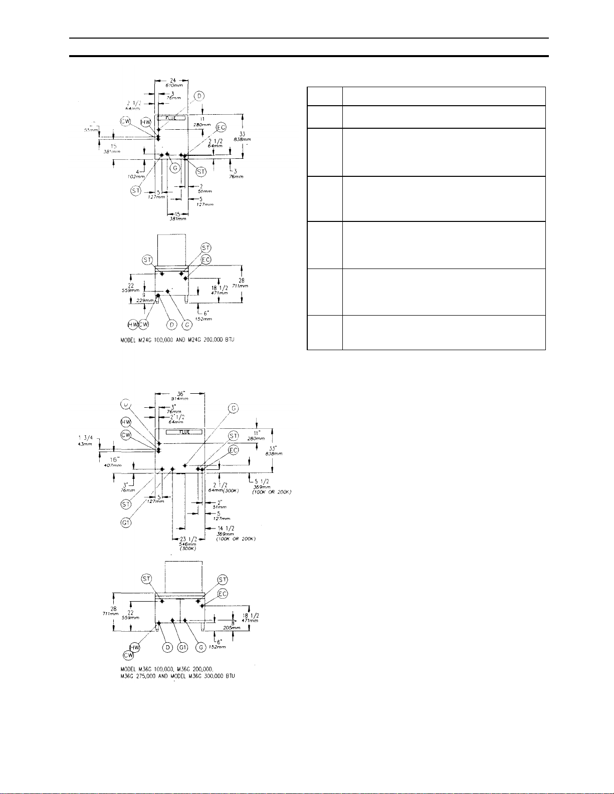
SERVICE CONNECTIONS
Gas Operated
G Gas Connection - 3/4" IPS (100 & 200K B.T.U.)
G1 Gas Connection - 1" IPS (275 & 300K B.T.U.)
HW
CW
D
EC
ST
Hot Water - 3/8" (10mm) O.D. tubing for hot water to
boiler. Hot water lines will have a maximum of 50 PSI
(3.5 kg/cm ) and a minimum of 25 PSI (1.8 kgcm )
water pressure.
Cold Water - 3/8"
condenser. Cold water lines will have a maximum of 50
PSI (3.5kg/cm2)and a minimum of 25 PSI (1.8 kg/cm2)
water pressure.
Drain - Pipe full 2" (51mm) I.P.S. to flush floor drain
of 5 gallons (19 liters) per minute. DO NOT MAKE
SOLID CONNECTION TO FLOOR DRAIN.
Electrical Connection -120 volt A.C. 60Hz, 1/2"(13mm)
a least 90 C. Amp for 115 steam generator controls is
2 amps.
Steam Take-off steam powered equipment.
PAGE 4
NOTES
If equipment is installed where elevation exceeds 2,000 feet
(609.6 meters) above sea level, specify installation altitude
so that proper gas orifices can be provided.
The only available space to supply utilities to the gas boiler
is the 6" (152mm) space between the floor and the cabinet,
Allow 3" (76mm) space from side wall and 6" (152mm) from
real wall if adjoining walls are combustible.
CAUTION
Before connecting water to this unit, water supply should be
analyzed to make sure hardness is no greater than 2.0
grains and pH level is wit hin the range of 7.0-8.5. Water
which fails to meet these standards should be treated by
installation of water conditioner. EQUIPMENT FAILURE
CAUSED BY INADEQUATE WATER QUALITY IS NOT
COVERED UNDER WARRANTY.
WASTE LINE INSTALLATION
The drain port of the unit is marked with a colored tag and is
located at the lower rear left side of the boiler as viewed
from the front. This exhaust line may be left open if the
boiler has to be situated in a tiled floor depression or a tiled
curb section that is equipped with drain facilities. If this is
not the case, then a 2" (51mm) I.P.S. drain line must be
connected to divert the exhaust to the floor drain. If it is
necessary to use more than three elbows, increase the size
of the waste line accordingly.
NOTE: PVC & CPVC PIPE ARE NOT ACCEPTABLE
MATERIALS FOR DRAINS.
WARNING: DO NOT UNDER ANY CIRCUMSTANCE
CONNECT THE EXHAUST DRAIN LINE DIRECTLY TO A
SEWER LINE.
OPERATING INSTRUCTIONS GAS OPERATED STEAM GENERATORS
STANDING PILOT MODELS:
M24G100, M36G100, M24G200, M36G200, M24G100A, M36G100A, M24G200A, M36G200A, M36G300, M36G300A
GLOW COIL MODELS:
M24G100-4, M36G100-4,M24G200-4, M36G 200-4, M24G100A -4, M36G100A-4, M24G200A-4,M36G200A4,M36G300-4, M36G300A -4
Market Forge has two types of steam generators; one has an automatic drain, the other a manual one. Automatic boilers
are also capable of being drained manually. To determine which you have, refer to lighting instruction plate located on
the inside of cabinet door, which will identify the steam generator as being automatic or manual.
AUTOMATIC OR MANUAL DRAIN STEAM GENERATOR
First check to be sure that:
E. BE SURE PILOT IS LIT. (STANDING PILOT UNITS ONLY)
A. WATER switch is in the OFF position.
B. WATER supply valve is OPEN.
C. ELECTRICITY is connected to ALL units.
D. GAS or STEAM is turned on.
F. That steam generator drain valve is closed.
G. Then proceed with daily operating procedure.
DAILY OPERATING PROCEDURE
STEP 1 close STEAM GENERATOR DRAIN VALVE.
(MANUAL DRAIN UNITS ONLY)
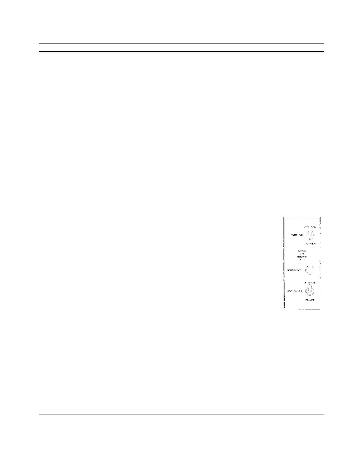
STEP 2 Flip WATER switch from OFF to ON.
STEP 3 Wait 5 minutes for water to fill in steam generator. (Gauge glass should
be 2/3 full.)
STEP 4 Flip HEAT switch from ON to OFF and release back to ON immediately.
Indicator light will come on. (This is necessary to manually reset the unit.) This also
turns on the HEAT.
DAILY SHUT-DOWN
STEP 1 Flip WATER switch OFF. if this is an automatic steam generator,
it will drain itself. If this is a manual steam generator, open drain valve,
drain steam generator and close valve.
STEP 2 After steam generator has completely drained repeat Steps 2 & 3 of DAILY
OPERATING PROCEDURE. (Water to remain in steam generator until next daily
use.)
PROLONGED SHUT-DOWN AND CLEANING INSTRUCTIONS
STEP 1 Flip WATER switch OFF. If this is an automatic steam generator, it will drain itself. If this is a
manual steam generator, open drain valve, drain steam generator and close valve.
STEP 2 Turn gas valve to OFF.
STEP 3 Steam generator must be cleaned . Refer to steam generator cleaning instructions for
modular steam generator, Page's 31-33, for complete instructions.
PAGE 5

OPERATING INSTRUCTIONS GAS OPERATED BOILERS (continued)
CAUTION: BE SURE TO READ
Disconnect The Power Supply to the boiler before servicing or cleaning.
Keep the appliance area free and clear of combustibles.
Do not obstruct the flow of combustion and ventilation air.
Keep this manual for future reference.
Contact the factory, the factory representative, or an authorized service company to
perform maintenance and repairs.
In the event of a power failure, no attempt should be made to operate the appliance.
Be sure the water switch is in the down position.
LIGHTING INSTRUCTION, STANDING PILOT
(Be sure the boiler drain valve is closed)
1 .Turn the gas valve to OFF. Wait 5 minutes for unburned gas to vent.
2. While this is taking place, flip WATER switch from OFF to ON. Wait 5 minutes for water to fill in the
boiler.
3. Turn gas valve knob counter-clockwise from OFF to PILOT.
4. Push the valve knob in all the way, light the pilot and hold the knob, depressed, for about 1 minute
to allow the pilot to heat the thermocouple.
5. Release knob, If the pilot goes out when the knob is released, return the knob to OFF and repeat
steps 1,3, and 4.
6. Turn the gas valve counter-clockwise to ON position.
7. When the boiler is filled it is necessary to manually reset the unit by flipping the HEAT switch from
ON to OFF and release back to ON immediately. The RED light will come on and the main gas
burners will ignite.
LIGHTING INSTRUCTION, GLOW COIL
(Be sure boiler drain valve is closed)
1 .Turn the gas valve to OFF. Wait 5 minutes for unburned gas to vent.
2. While this is taking place, flip the WATER switch from OFF to ON. Wait 5 minutes for water to fill in
the boiler.
3.Turn the gas valve to ON position.
4. When the boiler is filled it is necessary to manually reset the unit by flipping HEAT switch from ON
to OFF and release back to ON immediately. The RED light will come on and the main gas burners
will ignite.
PAGE 6
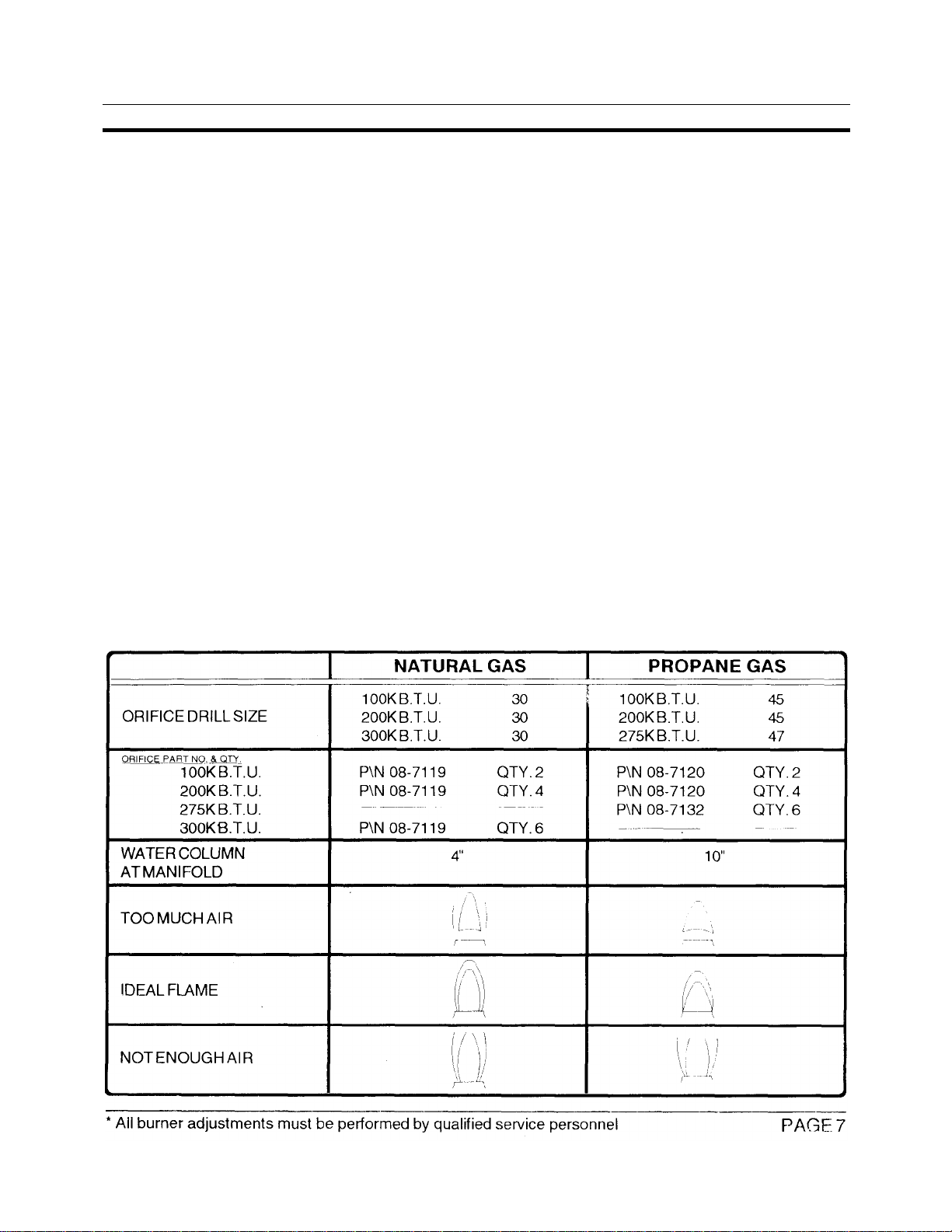
BURNER ADJUSTMENT
*ADJUSTING THE BURNERS
The boiler has been adjusted and tested to operate with the type of gas indicated on the
nameplate. However, as the characteristics of gas will sometimes vary in another location,
minor adjustment may have to be made to establish the most efficient burner flame.
To Adjust:
1. SEE BOILER OPERATING INSTRUCTIONS AND LIGHT THE BOILER.
2. The correct size orifice is factory installed
Observe the flame on each burner and open or close the air shutters of each to
establish the best possible adjustment. If proper flame adjustment cannot be
made refer to the chart below which shows the proper water column pressure for
the type of gas used. Take a water column measurement at the removable plug
in the center of the gas manifold.
A. IF GAS PRESSURE IS LOW:
Check your gas supply line for a restriction. If no restriction exists, check with your Natural
gas supplier to provide at least 5" of water column pressure in the gas supply line. If no
restriction exists and Propane gas is being used, the tank pressure regulator should be
adjusted to supply at least 11" of water column pressure in the gas supply line. If this
adjustment cannot be made to your satisfaction, the gas supplier should be notified.
B. IF GAS PRESSURE IS TOO HIGH
Adjust the pressure regulator on the boiler gas valve to reduce the pressure if Natural gas is
being used. If Propane gas is being used, adjust the pressure regulator supplied by the gas
supplier. If the regulator cannot be adjusted, notify the gas supplier.

TEST PROCEDURES -DUAL FUNCTION LIQUID LEVEL CONTROL
MARKET FORGE #08-6328 (120V) MARKET FORGE #08-6329 (240V)
The following is a troubleshooting guide designed to Determine if the Dual Function Control is working properly. It is not
designed to find out why the control has failed.
The Dual Function control is two controls in one, one half being the feed water control, the other half the low level cutoff
portion.
TOOLS NEEDED:
A digital or analog V -O-M (volt Ohm-Milliamp meter) and a set of test jumpers (alligator type).
PROCEDURE:
1. Turn off power to the control
2. Remove the wires #100, #101, #102 from the probe connections "H", "LLCO" and "G".
3. Remove the wires from the contact connections "COM", #104, and "N.O". from both relays.
CAUTION: Internal Jumper from "L1" to "COM" will not be hot when power is reapplied. Temporarily
tape free end.
4. Using the Ohm meter, check to see if the normally opened contact is open and the normally closed
contact is closed.
5. Turn power on to control. Check with the voltmeter to see if the voltage being applied to "L1"" &
"L2" is 120 VAC (+10% -15%), or 240 VAC if so equipped.
6. When power is turned on, the LED on the side away from the transformer should light and the relay
next to the LED should be energized. Checking with the Ohm meter, the normally open contact should
be closed and the normally closed contact should be open. Bringing power to the control should not
change the side of the control that contains the transformer.
7. Place a test jumper wire from either "G" terminal to the "H" terminal. After a 10 second (+/- 2) time
delay, the LED will go out and the relay next to this LED should deenergize returning the contacts to
their original state, (Normally open should be open, Normally closed should be closed)
8. Removing the test jumper from "G" and "H" should relight the LED and energize the relay.
9. Place a test jumper wire from either "G" terminal to the "LLCO" terminal. The LED next to the
transformer should energize. Checking with Ohm meter, the normally open contact should be closed
and the normally closed contact should be open.
10. Remove the test jumper from "G" and "LLCO". The LED should remain lit for about 3 seconds ( +/- )
before going out. The relay should deenergize at this time. The contacts should return to their original
state.
11. If the above test shows that the control is operating properly, check all probe and solenoid wiring
and the condition of the electrodes (clean insulator) in the steam chamber. Check the conductivity of
the liquid to make sure it is below 4.7K OHMS/CM
12. If after replacing all wires, the system still does not operate properly, contact the factory
PAGE 8
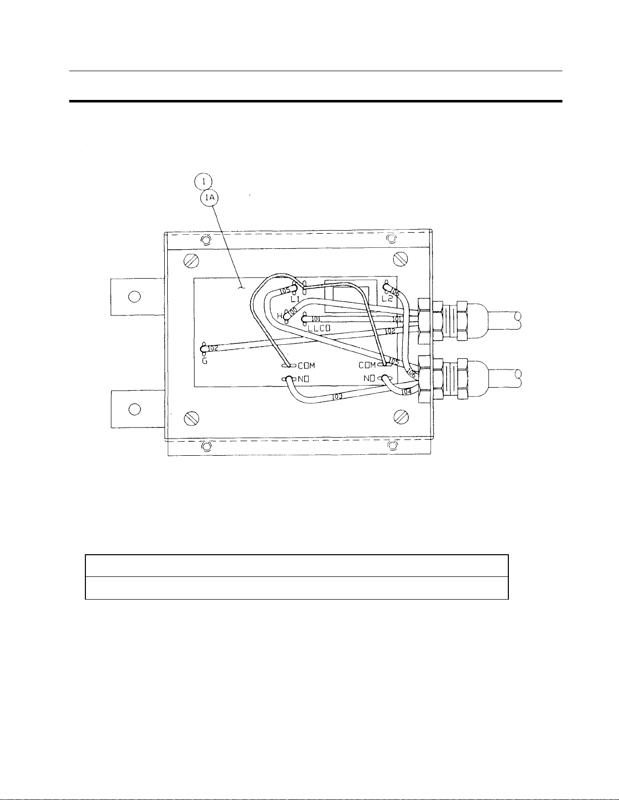
FRONT VIEW -WITHOUT COVER & GASKET-DUAL FUNCTION LIQUID LEVEL
CONTROL MARKET FORGE #08-6328 (120V) MARKET FORGE #08-6329 (240V)
1 08-6328 Liquid Level Control Board 120 V
1A 08-6329 Liquid Level Control Board 240 V (EX PORT)
PAGE 9

TEST PROCEDURES -DUAL FUNCTION LIQUID LEVEL CONTROL
MARKET FORGE #08-6407 (120V) (CALIF.)
The following is a troubleshooting guide designed to find out if the Dual Function and Series 26 Controls are working
properly. It is not designed to find out why the controls have failed.
The Dual Function control is two controls in one, one half being the feed water control, the other half the low level cutoff
portion. The Series 26 is strictly a secondary low level cutoff.
Tool Needed:
A digital or analog V -O-M (volt-Ohm-milliamp meter) and a set of test
jumpers (alligator type).
1) Turn off power to the control package.
2) Remove the wires #100, #101, #102 from the probe connections "H", "LLCO" and "G" on the dual
function and "LLCO/130" and "G" on the Series 26.
3) Remove the wires from the contact "COM", #104, and "N.O." from both relays on the dual function
and the relay on the Series 26. CAUTION: The Internal Jumper from "L1" & "COM" will not be hot
when power is reapplied. Temporarily tape free end.
TESTING THE DUAL FUNCTION:
4) When the power is turned on, the LED on the side away from the transformer should light and the
relay next to the LED should be energized. Checking with Ohm meter, the normally open contact
should be closed and the normally closed contact should be open. Bringing power to the control
should not change the side of the control that contains the transformer.
5) Place a test jumper wire from either "G" terminal to the "H" terminal. After a 10 second (+/-2 sec) time
delay, the LED will go out and the relay next this LED should deenergize returning the contacts to
their original state. (Normally open should be open, Normally closed should be closed)
6) Removing the jumper from "G" and "H" should relight the LED and energize the relay.
7) Place a test jumper wire from either "G" terminal to the "LLC" terminal. The LED next to the
transformer should light and the relay next to the transformer should energize. Checking with the
Ohm meter, the normally open contact should be closed and the normally closed contact should be
open.
8) Remove the test jumper from "G" and "LLCO". The LED should remain lit for about 3 seconds (+/-)
before going out. The relay should deenergize at this time. The contacts should return to their
original state.
TESTING THE SERIES 26:
9) With power still applied to control package, place a test jumper wire from "G" terminal to the "LLCO"
terminal. The LED should light and the relay should energize. Checking with Ohm meter, the
normally open contact should be closed and the normally closed contact should be open.
10) Remove the test jumper from "G" and "LLCO", The LED should remain lit for about 3 seconds (+/-)
before going out. The relay should deenergize at this time. The contacts should return to their original
state.
11) If the above test shows that the control is operating properly, check all probe and solenoid wiring
and the condition of the electrodes (clean insulator) in the steam chamber. Check the conductivity of
the liquid to make sure it is below 4.74K OHMS/CM
12) If after replacing all wiring, the system still does not operate properly, contact the factory.
PAGE 10
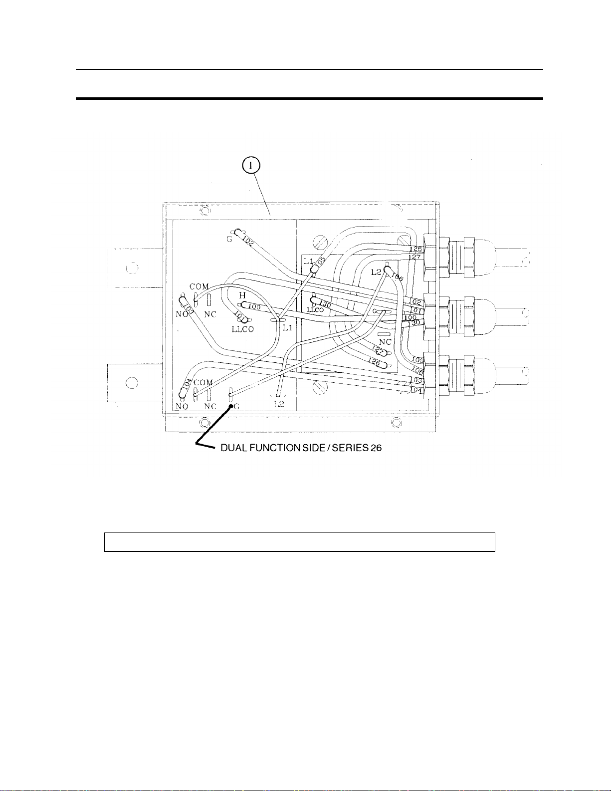
FRONT VIEW -WITHOUT COVER & GASKET-DUAL FUNCTION LIQUID LEVEL
CONTROL MARKET FORGE #08-6407 (120V) (CALIFORNIA)
1 08-6407 Liquid Level Control Board, California, 120V
PAGE 11

GENERAL TROUBLE SHOOTING GUIDE
heat
*2. If connections are secure. replace
TROUBLES POSSIBLE CAUSE REMEDY
Pilot will not ignite or does not hold.
1. Gas not reaching unit. 1. Check to make sure gas is on and
gas line is purged of air.
2. Main "gas cock knob" not in pilot
position.
3. Main "gas cock knob" not
depressed long enough to prethe pilot thermocouple.
4. Air pocket or clog in gas line. *4. Purge or blow out gas line.
5. Defective wiring or poor con-
nection at pilotstat power unit.
6. Thermocouple not generating
sufficient millivolts to operate.
7. Defective sw itching across either
the water level control or pressure
switches.
8. Defective gas valve. *8. Replace gas valve.
2. Depress and turn "main gas cock"
to pilot position-(refer to lighting
instructions).
3. Hold valve depressed for longer
period of time (one minute).
*5. Check - replace or tighten.
*6. Replace thermocouple.
*7. Make continuity check - replace
units that are defective.
Water enters boiler very slowly.
not light when water switch is
manually reset.
Boiler overfills with water
1. Clogged strainer screen on right
solenoid valve
2. Debris or lime accumulation on
seat of right valve.
1. Indicator light defective. *1. Replace. Indicator light, on control box, does
2. Time delay relay wiring loose or
defective.
1. Probes scaled. *1. Clean.
2. Water supply valve fails to close. *2. Clean valve seat or replace valve.
3. Defective water level control. *3. Follow the test procedure on
*1. Clean or replace strainer screen.
P/N 08-4871
*2. Clean valve seat.
the time delay relay.
pages 8 or 10. Replace if defective.
* Service must be performed by qualified personnel only.
PAGE 12
 Loading...