

Page 1

M24G & M36G
GAS OPERATED BOILERS
PARTS AND SERVICE MANUAL
EFFECTIVE AUGUST 29, 2014
The Company reserves the right to make substitution in the event that items specied are not available.
ERRORS: Descriptive and/or typographic errors are subject to correction.
44 Lakeside Avenue, Burlington, Vermont 05401 USA Telephone: (802) 658-6600 Fax: (802) 860-3732
Superseding All Previous Parts Lists.
MARKET FORGE INDUSTRIES
www.mi.com
P/N 14-0308 (8/14)
Page 2

TABLE OF CONTENTS
TROUBLESHOOTING ..................................................................3
GAS PRESSURE ADJUSTMENTS ......................................................5
WATER CONTROL BOARD TESING PROCEDURE ......................................6
WIRING DIAGRAM .....................................................................8
ILLUSTRATED PART LIST
24" BOILER BASE CABINET .......................................................... 10
PRESSURE SWITCH BOX, WITHOUT COVER..........................................11
CONTROL BOX ASSEMBLY, WITH AND WITHOUT COVER ............................. 12
PLUMBING, LEFT SIDE GAS BOILER, 24” ............................................. 13
FRONT VIEW GAS BOILER, 24”, 200K ................................................ 14
GAS TRAIN, 200K BTU BOILER SHOWN .............................................. 15
AUGUST 29, 2014 2 M24G & M36G GAS BOILERS
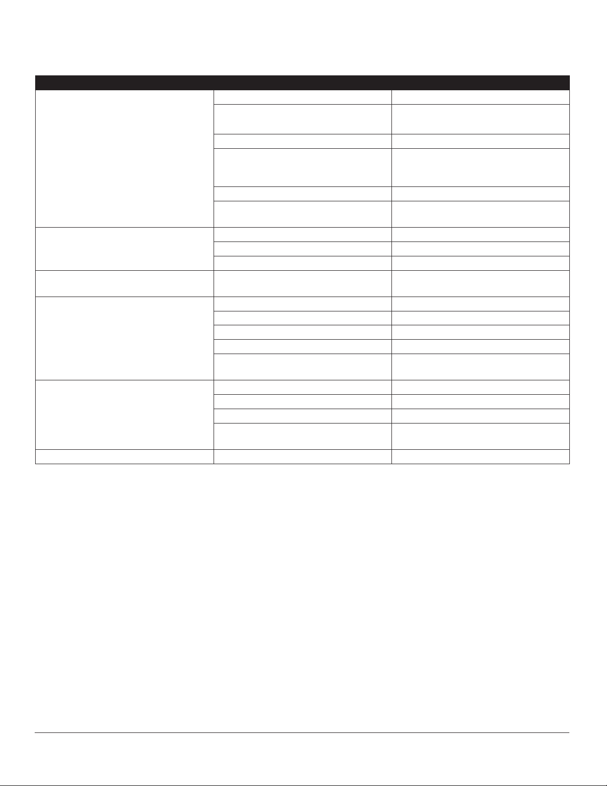
Page 3

TROUBLE POSSIBLE CAUSE(S) REMEDY
Pilot will not ignite or does not
hold.
TROUBLESHOOTING
Gas not reaching unit. Check to make sure gas is on and gas
line is purged of air.
Main “gas cock knob” not in ON position. Depress and turn “main gas cock” to pilot
position - (refer to lighting instructions).
Air pocket or clog in gas line. Purge or blow out gas line.
Defective wiring or poor connection at pilots at power unit.
Defective switching across either the water level control or pressure switches.
Defective gas valve. Replace gas valve.
Water enters boiler very slowly. Clogged strainer screen on water ll so-
lenoid valve
Debris or lime accumulation on seat of
water ll valve.
Boiler overlls with water. Probes scaled. Clean.
Water supply valve fails to close. Clean valve seat or replace valve.
Defective water level control. Follow the test procedure. Replace if de-
Main Burners will not ignite or will
not remain lighted.
Boiler fails to build up any pressure when the water is at the
correct level and the fuel switch is
turned on.
Boiler fails to cut off after reaching
operating pressure.
No water in boiler. Check to be sure water switch is on.
Main gas cock or supply line not open. Open.
Pressure switch set too low. Reset - if continuity check shows to be
No voltage to gas valve. Check main fuse.
Gas valve defective. Replace.
Check to see that main gas is turned on. Turn on.
Check to see that gas valve is in burners
“on” position.
Current ow is broken at water level control (ascertain with continuity check).
Current ow is broken at pressure control
or high limit control switches (ascertain
with continuity check).
Pressure switch set too high or defective. Adjust or replace if defective.
Check - replace or tighten.
Make continuity check – replace units
that are defective.
Clean or replace strainer screen. (P/N
08-4871).
Clean valve seat
fective.
Check to be sure main water supply is on
and the electrical supply to unit is on.
defective - replace.
Turn to burners “on”.
Check for voltage thru right side of control
board, replace if defective.
Re-adjust to proper setting -refer to instruction for re-adjustment, replace if defective.
Gas valve fails to cut off gas supply when
demands of pressure switch have been
met.
Water level in gauge glass uctuates up and down.
AUGUST 29, 2014 3 M24G & M36G GAS BOILERS
Top shutoff valve on water gauge glass
is closed.
Replace gas valve.
Open.
Page 4
TROUBLESHOOTING
TROUBLE POSSIBLE CAUSE(S) REMEDY
Boiler fails to reach full operating pressure of 5 lbs. or 15 lbs.
Safety valve blows off prematurely. Pressure set too high. Readjust pressure control.
Boiler builds up to pressure, shuts
down, fails to come back on.
Water does not enter boiler. Main water supply off. Turn on.
Cold water condenser does not function.
Air vent leaking. Not closing. Replace.
Pressure gauge reads inaccurately. Replace.
Pressure control and high limit control
switches are out of adjustment.
Safety valve not seating properly. Purge manually or replace.
Water level too high. Adjust water level control - check wa-
Air vent not venting properly. Replace.
Insufcient ames on burners or im-
proper gas supply.
Pressure gauge reads incorrectly. Replace.
Lime or debris on seat of valve Purge or replace.
High limit switch set to low or operating
pressure control switch set too high.
Power not reaching unit. Check main fuse or circuit.
Probes Dirty. Remove & Clean
Water level control board defective. See test procedure.
Solenoid valve defective If Voltage is veried at solenoid coil, but
Main water supply off. Turn on.
Thermostat defective. Replace if defective.
Loose coil nut. Tighten coil nut.
Solenoid coil not energized. Check coil for continuity, if open re-
Follow instructions for readjusting
ter feed valve for sticking - clean or replace.
See instructions on gas adjustments
Follow instructions for readjusting Replace if defective.
fails to open, replace solenoid.
place.
AUGUST 29, 2014 4 M24G & M36G GAS BOILERS
Page 5
GAS PRESSURE ADJUSTMENTS
If gas pressure is too low
Check your gas supply line for a restriction. If no restriction exists, check with your Natural gas supplier to provide
at least 5” of water column pressure in the gas supply line.
If no restriction exists and Propane gas is being used, the
tank pressure regulator should be adjusted to supply at
least 11” of water column pressure in the gas supply line.
If this adjustment cannot be made to your satisfaction, the
gas supplier should be notied.
If gas pressure is too high
Adjust the pressure regulator on the boiler gas valve to reduce the pressure if Natural gas is being used. If Propane
gas is being used, adjust the pressure regulator supplied
by the gas supplier. If the regulator cannot be adjusted,
notify the gas supplier.
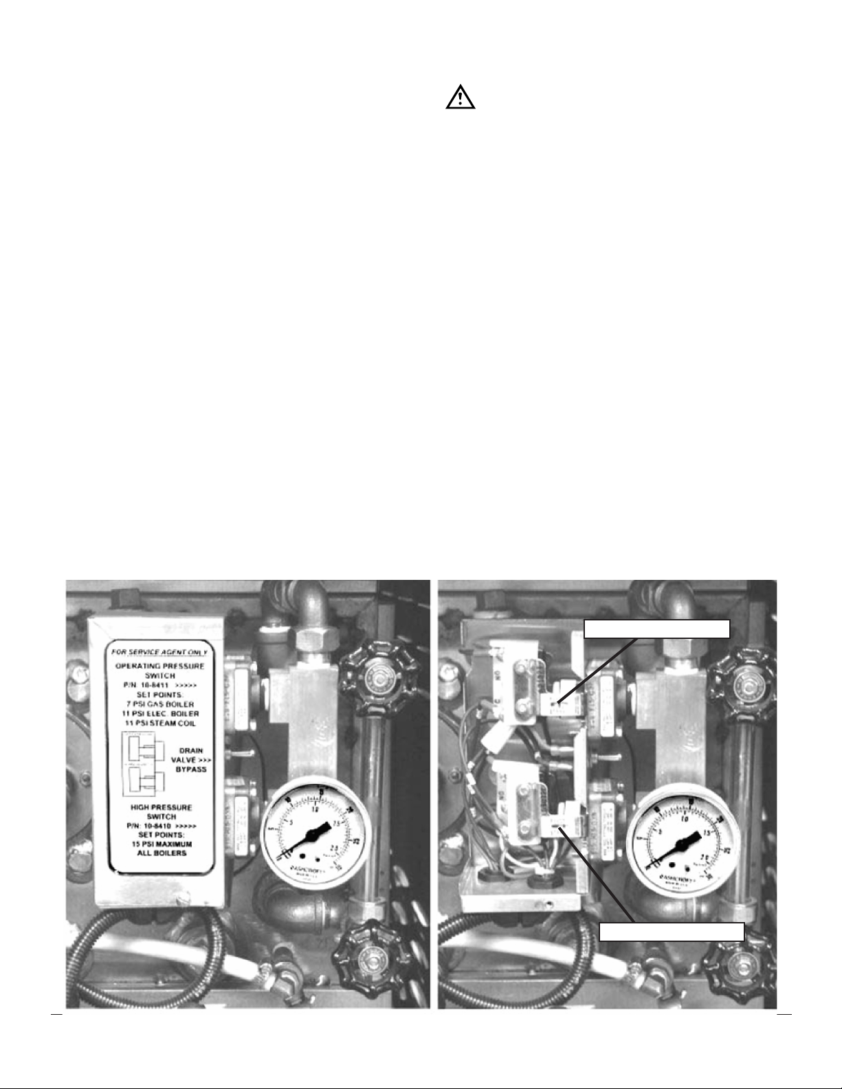
Pressure control switch adjustment
If boiler fails to maintain steam pressure in operating
range, pressure control switch may require adjustment.
1. Start boiler and allow pressure to build up to operating level - 7 PSI (1kg/cm²).
2. Check boiler pressure gauge. The gas burners should
cycle ON at 5 PSI and cycle OFF at 7 PSI.
3. If boiler does not come on when pressure gauge
reads 5 PSI and does not go off when pressure gauge
reads 7 PSI, proceed as follows:
WARNING
Because power must be on to adjust pressure
switches, be sure to protect against electrical
shock.
a. Remove screw and lift front cover off control box.
b. Hand adjust operating pressure control switch
and high limit pressure control switch by turning
adjusting nut (Knurled knob) clockwise to raise
and counter clockwise to lower actuation point.
Switch should be set so that boiler comes on
when boiler pressure gauge reads 5 PSI and
goes off when gauge reads 7 PSI. Hi limit switch
should be set so that boiler will shut off if pressure reaches 15 PSI.
c. The actuation value (differential) is factory set
and cannot be changed.
d. The cold water condenser thermostat is preset
at factory.
e. Repeat steps, 1, 2, and 3. If 5 to 7 PSI boiler
pressure gauge reading is obtained during boiler
operation, adjustment is correct. If proper adjustment cannot be made contact an authorized service agent.
f. After making adjustments, replace cover on pres-
sure switch box and screw.
OPERATING SWITCH
HI LIMIT SWITCH
AUGUST 29, 2014 5 M24G & M36G GAS BOILERS
Page 6
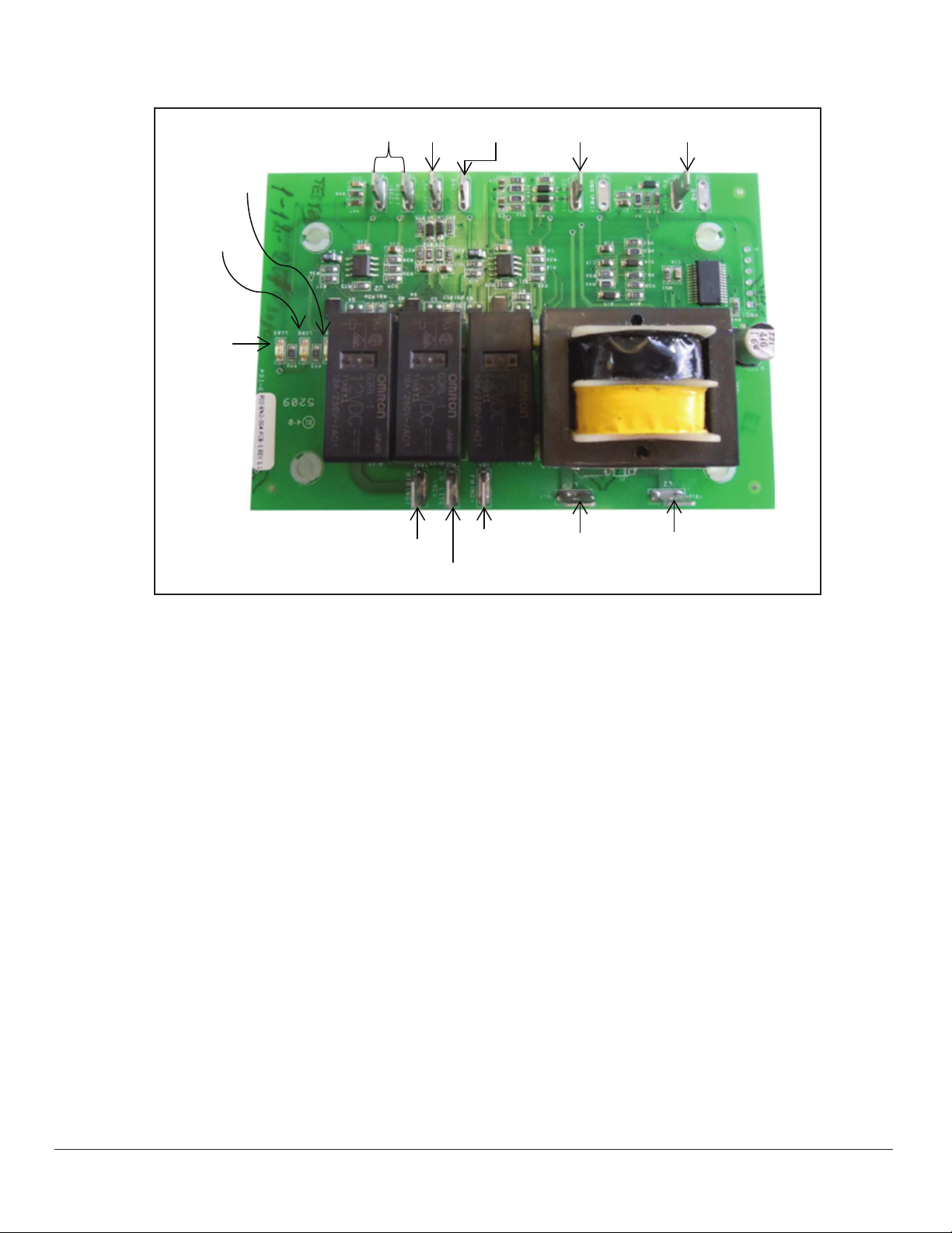
WATER CONTROL BOARD TESING PROCEDURE
LED 1
LED 2
LED 3
RESET
LW2
GND
LW1
FW - HIGH
HTA NO
LO LITE (NC)
FW (NO)
L1
L2
This test procedure is to be used to determine if the control is working properly. It is not intended to determine why
the control may have failed.
If testing shows that the control is operating properly,
check all probe and solenoid wiring and the condition of
the electrodes in the steam chamber.
Contact the factory if the boiler still does not operate properly after completing the testing.
Tools Needed:
• Digital or Analog V-O-M meter.
• Alligator clip type test jumpers (2 sets min.).
Turn Off Power to Control:
• Use V-O-M to verify there is no power at terminals L
1 & L2.
• Use V-O-M to verify that there is no power at terminals ‘FW(NO)’, ‘LO LlTE(NC)’ & ‘HTR(NO)’. If there
is power at any of these terminals, you will need to
nd the source and turn it off.
Remove Wires from Probe and Relay Switch Terminals:
• DO NOT remove wires from L 1 & L2 terminals.
• Tag wires and remove from probe and relay contact
terminals including ‘GND’ terminal.
• Tag and remove wires from ‘RESET’ terminals.
• Connect jumper wire to both ’RESET’ terminals.
Turn Power On to Terminals L 1 & L2:
• ‘LED l’ should turn on.
• ‘LED 2’ should be off.
• ‘LED 3’ should be off.
• Use V-O-M to verify that there is power at ‘FW(NO)’
& ‘LO LlTE(NC)’ terminals and no power ‘HTR(NO)’
terminals Test Feedwater Function:
• Connect jumper wire to ‘FW HIGH and ‘GND’ terminals.
• ‘LED l’ should turn off after a 10 second delay.
• Use V-O-M to verify that there is no power at the
‘FW (NO)’ terminal.
• Remove jumper from ‘FW HIGH’ and ‘GND’ terminals. . ‘LED l’ should turn on.
• Use V-O-M to verify that there is power at the
‘FW(NO)’ terminal.
AUGUST 29, 2014 6 M24G & M36G GAS BOILERS
Page 7

WATER CONTROL BOARD TESTING PROCEDURE
Test Primary Low Water Function:
• Connect jumper wire to ‘LW(1) and‘GND’ terminals.
• ‘LED 2’ should turn on.
• Remove jumper wire from ‘LW(1)’ and ‘GND’ termi-
nals.
• ‘LED 2’ should turn off after a 3 second delay.
• Connect jumper wire to ‘LW(1)’ and ‘GND’ terminals.
• ‘LED 2’ should turn on.
• Use V-O-M to verify that there is power at the ‘LO
LlTE(NC)’terminal and no power at the ‘HTR(NO)’
terminal.
• Remove the jumper wires from the ‘RESET’ terminals.
• ‘LED 3’ should turn on.
• Use V-O-M to verify that there is no power at the
‘LO LlTE(NC)’ terminal and power at the ‘HTR(NO)’
terminal.
• Connect jumper wire to ‘RESET’ terminals.
Test Secondary Low Water Function:
• Connect jumper wire to ‘LW(2)’ and ‘GND’ terminals.
• ‘LED 3’ should remain off.
IF ALL FUNCTIONS WORK, TROUBLE-SHOOTING
OTHER COMPONENTS WILL BE REQUIRED!
• Remove jumper wire from ‘LW(2)’ and ‘GND’ terminals.
• ‘LED 3’ should turn off after a 3 second delay.
• USE V-O-M to verify that there is power at the ‘LO
LlTE(NC)’ terminal and no power at the ‘HTR(NO)’
terminal.
• Connect jumper wire from ‘LW(2)’ and ‘GND’ terminals.
• ‘LED 3’ should remain off.
IMPORTANT
Jumper wire between ‘LW(1) and ‘GND’
terminals must remain in place to test secondary low water function. IF ANY OF THE
FUNCTIONS DO NOT WORK, REPLACE THE
BOARD!
AUGUST 29, 2014 7 M24G & M36G GAS BOILERS
Page 8

WIRING DIAGRAM
WIRING DIAGRAM FOR NEW GENERATION BOILERS – 100K, 200K, 300K BTU
AUGUST 29, 2014 8 M24G & M36G GAS BOILERS
Page 9

WIRING DIAGRAM
SCHEMATIC DIAGRAM FOR NEW GENERATION BOILERS – 100K, 200K, 300K BTU
AUGUST 29, 2014 9 M24G & M36G GAS BOILERS
Page 10

24" BOILER BASE CABINET
ITEM PART NO. DESCRIPTION
1 91-8892 Flue Outer, 24” Front
1 91-8938 Flue Outer, 36” Front
2 91-8893 Flue Outer, 24” Back
2 91-2713 Flue Outer, 36” Back
3 98-0593 Flue Inner Assembly, 100 & 200k Boiler
3 91-8936 Flue Inner Assembly, 300k Boiler
4 08-5894 Market Forge Nameplate Logo
5 91-5795 Handle, Front
6 94-5007 Panel, Front Assembly, 24”
6 94-5006 Panel, Front Assembly, 36”
7 10-0631 Leg, 6”
7 08-5206 Leg, 8”
7 08-5211 Leg, 10”
7 08-5208 Leg, Flanged 6”
7 10-0326 Caster, 5”
8 98-3968 Trim, Edge
9 98-3978 Glass
10 98-3991 Gasket, Adhesive
11 98-4010 Panel, Side (Single Panel)
12 98-3995 Panel, Rear Assembly, 24”
12 98-3996 Panel, Rear Assembly, 36”
13 94-5011 Panel Clips (not shown)
AUGUST 29, 2014 10 M24G & M36G GAS BOILERS
Page 11

PRESSURE SWITCH BOX, WITHOUT COVER
ITEM PART NO. DESCRIPTION
1 94-5064 Box, Pressure Switch
2 10-8410 Pressure Switch, Hi-Limit
3 10-8411 Pressure Switch, Operating
4 98-3875 Switch, Drain By-Pass
5 08-7933 Manifold, Pressure Switches
6 10-4804 Pressure Gauge
7 09-4844 Union Elbow, 1/2”
AUGUST 29, 2014 11 M24G & M36G GAS BOILERS
Page 12

CONTROL BOX ASSEMBLY, WITH AND WITHOUT COVER
ITEM PART NO. DESCRIPTION
1 08-6549 Switch, Power
2 94-5127 Switch, Manual Reset
3 10-5052 Light, Red
4 08-6450 Transformer, 120-240V
5 98-1680 Board, Water Level Control
6 94-5022 Ignition Module
7 08-6472 Relay Tube
8 08-6475 Relay Base
9 98-3877 Relay Bracket
10 94-5003 Artwork, Control Box
11 94-5066 Cover
12 94-5069 Terminal Strip
AUGUST 29, 2014 12 M24G & M36G GAS BOILERS
Page 13

PLUMBING, LEFT SIDE GAS BOILER, 24”
ITEM PART NO. DESCRIPTION
1 10-0239 Hose, Drain 1”
2 10-4137 Clamp Hose
3 91-6927 Box Drain Assembly
4 10-7955 Valve, Safety, 15 PSI
5 10-1058 Valve, Cold Water Condenser, 120V
6 10-1311 Valve, Drain, 120V
7 08-4822 Valve, Boiler Feed
8 08-7959 Condenser, 3/8” Hose, 21” Long
9 98-3894 Copper, Nozzle
10 98-3914 Comp Fitting, 3/4”
11 98-1401 Valve, Check
12 10-0287 Hose, Drain, 3/4”
13 10-4137 Clamp, Hose
14 08-7974 Clamp, Hose
15 98-3892 Condenser Thermostat
16 10-1152 Plug
AUGUST 29, 2014 13 M24G & M36G GAS BOILERS
Page 14

FRONT VIEW GAS BOILER, 24”, 200K
ITEM PART NO. DESCRIPTION
1 08-4900 Water Inlet, Manual Valve
2 94-5023 Gas Valve
3 94-5033 Gas Manifold, 100K & 200K Boilers
3 94-5034 Gas Manifold, 300K Boilers
4 10-3661 Drain Valve, Maunal
5 10-1311 Drain Valve, Automatic
6 91-5112 Probe Plate Assy
7 10-7955 Safety Valve
8 10-4556 Air Vent
9 08-4991 Tee, 3/4”, Side Outlet
10 94-5065 Cover, Pressure Switch Box
11 94-5010 Label, Pressure Switch Box
12 94-5128 Gas Valve, 120V, Propane Kit
13 08-7970 Hose, Water, 20”
14 98-3864 Flex Conduite
AUGUST 29, 2014 14 M24G & M36G GAS BOILERS
Page 15

GAS TRAIN, 200K BTU BOILER SHOWN
ITEM PART NO. DESCRIPTION
1 98-3923 Vent, Bleeder
1A 08-7970 Bleeder Hose
2 10-7955 Valve, Safety, 15 PSI
3 91-7031 Probe Plate
4 08-4413 Gasket, Probe Plate
5 08-6399 Probe, Lowest Probe
6 08-6398 Probe
7 08-6364 Probe
91-5112 KIT that includes items 3, 4, 5 and 6
8 91-8810 Cover Hand Hole
9 08-4415 Gasket Hand Hole
10 10-2414 Nut
11 10-2310 Washer
12 91-8811 Yoke
13 10-4754 Glass, Sight Gauge, 6”
14 90-0039 Rubber & Brass Washer Set
15 10-2728 Kit, Complete Includes: Valves, Glass
16 98-3928 Elbow 1/2”, Side Outlet
17 98-3944 Stud, 1/4-20
18 98-3945 Kep Nut
AUGUST 29, 2014 15 M24G & M36G GAS BOILERS
Page 16
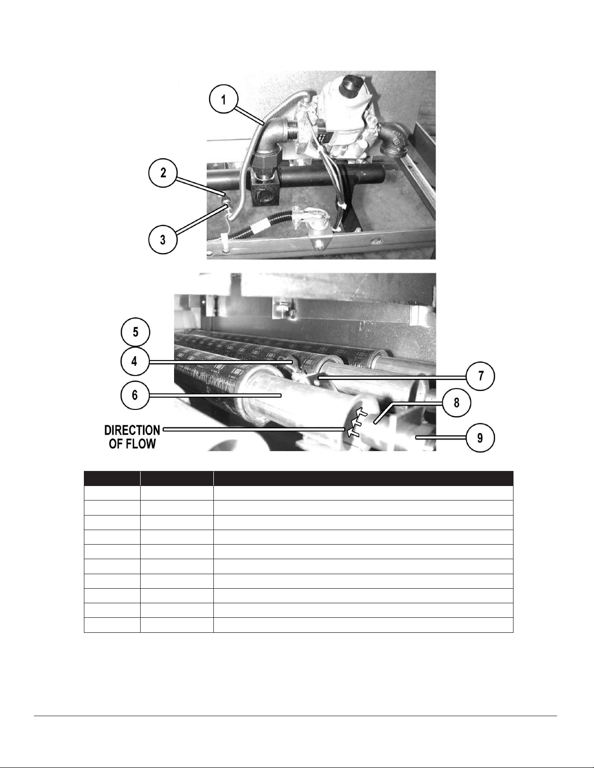
GAS TRAIN, 200K BOILER SHOWN
ITEM PART NO. DESCRIPTION
1 08-7832 Tube, Flex, Gas Line
2 10-1154 Compression Coupling
3 98-3890 Pilot Tube
4 94-5099 Spark Pilot and Igniter
5 94-5129 Pilot Orice, Prop.
6 94-5046 Burner
7 94-5052 Pilot Brkt
8 08-7119 Orice, Natural Gas (Brass #30)
8 08-7120 Orice, Propane (#45 Black)
9 08-7118 Orice Hood
AUGUST 29, 2014 16 M24G & M36G GAS BOILERS
 Loading...