

Page 1
ELECTRICALLY OPERATED
FACSIMILE tt
(617) 387
-
4456
35 Garvey St., Everett, MA
02149
-
4403
Tel.
(617) 387
-
STEAM GENERATOR
OWNERS MANUAL
OUTSIDE MA (800) 227-2659
Form No. S-2379 Printed in U.S.A. 3/90
MODELS:
M24E18, M24E24, M24E32,
M24E36, M24E42, M24E48,
M36E18, M36E24, M36E32,
M36E36, M36E42, M36E48
4100, Telex 94-9414, Cable MAFORCO
Page 2

TABLE OF CONTENTS
Page
Introduction................................................................. 1
How To Use This Manual ..................................... 1
Theory of Operation ................................. 1
Receiving Instructions..................................... 2
Installation Instructions........................ 2,3
Operating Instructions................................................... 4,5
Liquid Level Control Diagram..................................... 6, 8
Trouble Shooting Liquid Level Control Board ..................... 7, 9
General Trouble Shooting Guide ......................................... ....................10,11,12
Operation/Adjustment of Pressure Reducing Valves ............. 13
Adjustment, Pressure Control Switches ........................ 14
Control Box Wiring Diagram ..................................... 15
Wiring Diagram, Heating Circuit ............................... 16
Wiring Diagram, Heating Circuit (Export) ..................... 17
24" Cabinet Base .................................... 18
36" Cabinet Base ................................................ 19
Steam Generator - Right Side View............................. 20
Control Box Assy. (Covered & Uncovered) .......................... 21
Heating Elements......................................................... 22
Plumbing Section (Left Side View)................................ 23
Contactors & Liquid Level Control Box ................................ 24
A - Small Generator w/Contactor Box ................................... 25
B - Large Generator w/Contactor Box.................................. 25
C - Electric Modular Base Steam Generator.......................... 25
Page 3

INTRODUCTION
Market Forge, in the interest of both costs and efficiency to the purchasers of its equipment, has designed these steam
generators with the latest type automatic controls in order to make it easier for the operator to use and maintain this
equipment. In addition, standard components are utilized on all models of steam generator equipment unless variances in
size or capacity dictate a divergence from this policy for more efficiency in operation. This parts and service manual is written
and illustrated to cover all steam generator equipment that uses electricity as a source of power other than those which have
been custom designed under special order.
HOW TO USE THIS MANUAL
The pictures of components are aids to the identification, disassemb ly and assembly of parts. The parts listings provide
information necessary for the ordering of replacement parts (proper part names and part numbers). When requesting parts or
service, always furnish the model and serial number of your complete unit, which will indicate to Market Forge Service
Division the type of steam generator with which you are equipped. This information can be found on the nameplate attached
to the steam generator frame.
THEORY OF OPERATION FOR ELECTRIC STEAM GENERATORS
Explanation of how the control system works on manual and automatic electric steam generators.
With the steam generator filled with water to its proper level and the fuel switch turned to its on position, the contactors will
pull in and permit the completion of the electric circuit to the heating elements. When the steam generator builds up to its set
pressure the pressure switch on the left side in the control box opens. This will open up the circuit to the coil in the contactor,
which in turn will drop out the contacts in the contactor and shut off the electricity. As the pressure in the steam generator
drops off, the pressure control switch will again come into operation and complete the circuit and build the steam generator
back up to its set pressure. When the operator wishes to stop all generation of steam he need only to place the fuel switch in
the off position.
Product Service Dept. Market Forge Co.
35 Garvey Street Telephone 617-387-4100
Page 4

35 Garvey St., Everett, MA 02149 Tel. (617) 387-4100
ELECTRICALLY OPERATED STEAM GENERATORS
WARNING: READ THIS BEFORE OPENING THE SHIPPING CONTAINERS
DO NOT AT ANY TIME LAY THE EQUIPMENT DOWN ON ITS BACK, SIDE, TOP OR FRONT. Doing so may damage
the equipment and invalidate the warranty.
RECEIVING INSTRUCTIONS:
Inspect the equipment before signing the bill of lading. The equipment supplied was tested and inspected before
shipment. The carrier accepted it as complete and without damage.
This merchandise became your property when it was accepted by the carrier at the factory. Market Forge cannot assume
responsibility for loss or damage during transit.
For this reason, you should immediately inspect for visible and concealed dama ge or shortages before signing for
shipment as follows:
1. Count the number of cartons and packages received to be sure they coincide with the bill of lading.
2. Visually check all cartons for external damage.
3. Remove all cartons from their skids to examine equipment for concealed damage. The carton is
nailed and strapped to the skid. It will be necessary to cut the straps and pry off the container.
4. After inspection, replace the cartons over the equipment on the skids to protect and secure the
equipment until it is ready for installation.
5. Sign for shipment if all is in order. Note shortages, external and concealed damage, if any, on the
bill of lading before accepting a partial or damaged shipment.
6. If necessary, contact the carrier immediately to file a claim. All claims must be filed by the receiver.
7. Do not remove the cartons or the skids from the cooking equipment until the unit has been
transported through the building to the actual set -up location. The cartons should remain on the
equipment as protection against dents and scratches.
Installation Instructions
SETTING IN PLACE:
INSTALLING LEGS:
Some models are shipped without legs. A separate carton will contain the legs. If your model is received this way be sure
to follow the installation sheet packed with the legs.
LEVELING:
In order for the steam generator to drain correctly it is important that it be level. Place level on cabinet top - both left and
right and front to back. If not level, adjust feet. On compartment cookers, check cooking compartment pan supports to
insure they are secure. Check by installing cooking pan to see if the pan supports are level.
PANELS AND DOORS:
Panels and doors for the cabinet may be shipped separate. Refer to installation instructions enclosed with panels and
doors for method of attaching. It is recommended that panels and doors be installed after mechanical connections are
made to avoid damage.
2
Page 5
Volts 18KW 24KW 32KW 36KW 42KW
1ph 3ph 3ph 3ph
3ph 3ph 3ph
240(220
-
240) 75 32 60 77 91
—
116
480 (360
-
500) 36 22 32 39 47
—
58
HW
2
amps.
adjacent steam powered equipment.
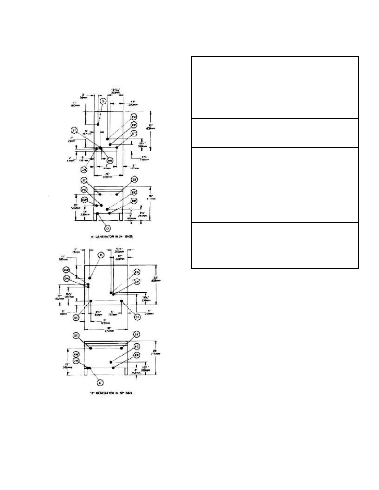
INSTALLATION ROUGH-IN REQUIREMENTS
EP Power Supply —Use wire suitable for at least
90°C. Nominal amp per line wire:
208(197.219) 86 50 66 89 100 117 —
Details of other electrical systems available upon request.
Hot Water— 3/8" N.P.T. for hot water to steam generator.
Hot water line shall have a maximum of 50 PSI (3.5 kg/cm2
and a minimum of 25 PSI (7.8 kg/cm22) water pressure.
CW
Cold Water—3/8" N.P.T. for cold water to condenser. Cold
water line shall have a maximum of 50 PSI (3.5 kg/cm2)
and a minimum of 25 PSI (1.8 kg/cm2) water pressure.
D
Drain—Pipe full 2" (50mm) I.P.S. to flush floor drain
capable of receiving water flowing at a maximum rate of 5
gallons 19 liters per minute. DO NOT MAKE SOLID
CONNECTION TO FLOOR DRAIN. PVC and CPVC are
not acceptable materials for drains.
EC Electrical Connection—120 volts AC, 60Hz,' single phase,
1/2" 13mm conduit connection or equivalent. Use wire
suitable for at least 90°C. Amp draw for generator controls:
ST Steam Take-off—Connecting locations for operation of
CAUTION:
Before connecting water to this unit, water supply
should be analyzed to make sure hardness is no
greater than 2.0 grains and pH level is within the
range of 7.0-8.5. Water which fails to meet these
standards should be treated by installation of a water
conditioner. EQUIPMENT FAILURE CAUSED BY
INADEQUATE WATER QUALITY IS NOT COVERED
UNDER WARRANTY .
3
Page 6

Operating Instructions
MARKET FORGE MODULAR STEAM GENERATOR OPERATING INSTRUCTIONS
WARNING: The installation of this appliance is to be in accordance with the current CAN 1-B149. 1 of CAN1-
B149.2 - Installation Code for Gas Burning Appliances and Equipment and/or Local Codes.
WARNING: All Electrical connections are to be made in accordance with CSA C22.1 Canadian Electrical Code
Part 1 and/or Local Codes.
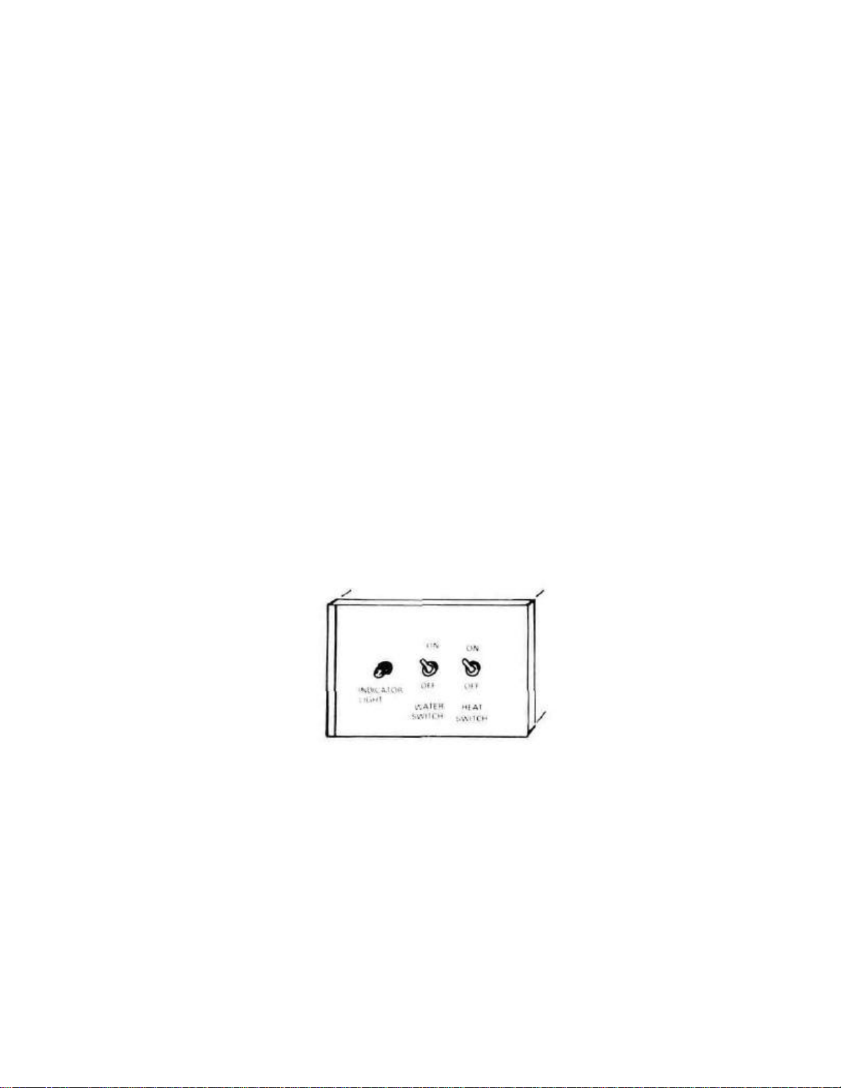
Market Forge has two types of steam generators; one has an automatic drain, the other a manual one. To determine which
you have, open cabinet doors and you will see a control box with 2 switches and an indicator light. Instruction label on the
control box will identify the steam generator as being automatic or manual.
DAILY OPERATING, SHUT DOWN & CLEANING INSTRUCTIONS FOR
AUTOMATIC STEAM GENERATORS
First check to be sure that:
A. WATER switch is in the off position.
B. WATER supply valve is OPEN.
C. ELECTRICITY is connected.
D. That STEAM is turned on.
E. Proceed with daily operating procedure.
DAILY OPERATING PROCEDURE
STEP 1 Flip WATER switch from OFF to ON.
STEP 2 Wait 6 minutes for water to fill in steam generator.
(Gauge glass should indicate approx. 2/3 full.)
STEP 3 Flip heat switch from ON to OFF and release back to ON. Indicator
light will come on immediately (This is necessary to manually reset
the unit.) This also turns on HEAT.
DAILY SHUT-DOWN AND CLEANING
STEP 1 Flip WATER switch OFF. (Indicator light will go out and
steam generator will automatically drain.)
STEP 2 After steam generator has completely drained, repeat Steps 1 & 2.
Water is to remain in steam generator until next day use.
STEP 3 Repeat Steps 1 & 2.
Water is to remain in steam generator until next day use
NOTES: If generator is not to be in use for extended periods, (2-3 mos.) contact your authorized
service dealer, for it must be cleaned and drained completely. Then add PM-Plus as per
instructions on Bottle.
If steam generator does not automatically drain when water switch is shut off, open manual
drain by turning knob counter clockwise. Electric steam generators should be blown-down
and refilled after every 4 hours of operation.
Page 7
DAILY OPERATING, SHUT-DOWN & CLEANING INSTRUCTIONS
First check to be sure that:
A. WATER and HEAT switches are in the OFF position.
B. WATER supply valve is OPEN.
C. ELECTRICITY is connected to ALL units.
D. STEAM is turned on.
E. Proceed with daily operating procedure.
DAILY OPERATING PROCEDURE
STEP 1 Close STEAM GENERATOR DRAIN VALVE.
STEP 2 Flip WATER switch from OFF to ON.
STEP 3 Wait 6 minutes for water to fill in steam generator. (Gauge glass should be 2/3 full.)
STEP 4 Flip WATER switch from ON to OFF and back to ON immediately.
Indicator light will come on. (This is necessary to manually reset the unit.)
STEP 5 Flip HEAT switch from OFF to ON. This turns on HEAT.
DAILY SHUT-DOWN AND CLEANING
STEP 1 Flip HEAT and WATER switches to OFF. (Indicator light will go out.)
STEP 2 Open steam generator drain valve, and drain completely.
STEP 3 Repeat Steps 1 & 2 of DAILY OPERATING PROCEDURE, (Water to
remain in steam generator until next daily use.)
STEP 4 For shutdown for extended periods steam, generator must be cleaned and drained
completely. Refer to steam generator cleaning instructions for modular steam
generators S-2299 for complete instructions.
CAUTION: BE SURE TO READ
Keep this appliance area free and clear from combustibles.
Do not obstruct the flow of ventilation air.
Keep this manual for future reference.
Contact the factory, the factory representative, or a local service company to perform maintenance and repairs.
In the event of a power failure, attempt should not be made to operate the appliance during power failure. Be sure water
switch is in the down position.
Page 8
Page 9

TEST PROCEDURES - MARKET FORGE #08-6328 (120V)
MARKET FORGE #08-6329 (240V)
The following is a troubleshooting guide designed to find out if the Dual Function Control is working properly. It
is not designed to find out why the control has failed.
The Series Dual Function control is two controls in one, one half being the feed water control, the other half the
low level cutoff portion.
Tools Needed: A digital or analog V-O-M (volt-Ohm-milliamp meter) and a set of test jumpers (alligator type).
1) Turn off power to the control.
2) Remove the wires #-100, #101, #102 from the probe connections "H, "LLCO" and "G".
3) Remove the wires from the contact connections "COM", #104 and "N.O." from both relays. CAUTION:
Internal Jumper from "L1" to "COM" will be hot when power is reapplied. Temporarily tape free end.
4) Using the Ohm meter, check to see if the normally opened contact is open and the normally closed contact is
closed.
5) Turn power on to control. Check with the voltmeter to see if the voltage being applied to "L1" & "L2" is 120
VAC (+10% -15%), or 240 VAC if so equipped.
6) When power is turned on, the LED on the side away from the transformer should light and the relay next to
the LED should be energized. Checking with the Ohm meter, the normally open contact should be closed and
the normally closed contact should be open. Bringing power to the control should not change the side of the
control that contains the transformer.
7) Place a test jumper wire from either "G" terminal to the "H" terminal. After a 10 second (+/-2) time delay, the
LED will go out and the relay next to this LED should deenergize returning the contacts to their original state,
(Normally open should be open, Normally closed should be closed)
8) Removing the test jumper from "G" and "H" should relight the LED and energize the relay.
9) Place a test jumper wire from either "G" terminal to the "LLCO" terminal. The LED next to the transformer
should light and the relay next to the transformer should energize. Checking with the Ohm meter, the normally
open contact should be closed and the normally closed contact should be open.
10) Remove the test jumper from "G" and "LLCO". The LED should remain lit for about 3 seconds (+/-) before
going out. The relay should deenergize at this time. The contac ts should return to their original state.
11) If the above test shows that the control is operating properly, check all probe and solenoid wiring and the
condition of the electrodes (clean insulator) in the steam chamber. Check the conductivity of the liquid to make
sure it is below 4.7K ohms/cm.
12) If after replacing all wires, the system still does not operate properly, contact the factory.
Page 10

Page 11

TEST PROCEDURES - MARKET FORGE #08-6407 (120V) (CALIF.)
The following is a troubleshooting guide designed to find out if the Dual Function and Series 26 Controls are working
properly. It is not designed to find out why the controls have failed.
The Series Dual Function control is two controls in one, one half being the feed water control, the other half the low level
cutoff portion. The Series 26 is strictly a secondary low level cutoff.
Tools Needed: A digital or analog V -O-M (volt-Ohm-milliamp meter) and a set of test jumpers (alligator type).
1) Turn off power to the control package.
2) Remove the wires #100, #101, #102 from the probe connections "H", "LLCO" and "G" on the dual function and
"LLCO/130" and "G" on the Series 26.
3) Remove the wires from the contact connections "COM", #104, and "N.O" from both relays on the dual function and the
relay on the Series 26. CAUTION: The Internal Jumper from "L1" & "COM" will be hot when power is reapplied.
Temporarily tape free end.
TESTING THE DUAL FUNCTION:
6) When power is turned on, the LED on the side away from the transformer should light and the relay next to the LED
should be energized. Checking with the Ohm meter, the normally open contact should be closed and the normally closed
contact should be open. Bringing power to the control should not change the side of the control that contains the
transformer.
7) Place a test jumper wire from either "G" terminal to the "H" terminal After a 10 second (+/-2) time delay, the LED will go
out and the relay next to this LED should deenergize returning the contacts to their original state. (Normally open should
be open, Normally closed should be closed)
8) Removing the jumper from "G" and "H" should relight the LED and energize the relay.
9) Place a test jumper wire from either "G" terminal to the "LLCO" terminal. The LED next to the transformer should light and
the relay next to the transformer should energize. Checking with the Ohm meter, the normally open contact should be
closed and the normally closed contact sh ould be open.
10) Remove the test jumper from "G" and "LLCO". The LED should remain lit for about 3 seconds (+/-) before going out. The
relay should deenergize at this time. The contacts should return to their original state.
TESTING THE SERIES 26:
11) With power still applied to control package, place a test jumper wire from "G" terminal to the "LLCO" terminal. The LED
should light and the relay should energize. Checking with the Ohm meter, the normally open contact should be closed
and the normally close d contact should be open.
12) Remove the test jumper from "G" and "LLCO". The LED should remain lit for about 3 seconds (+/-) before going out. The
relay should deenergize at this time. The contacts should return to their original state.
13) If the above test shows that the control is operating properly, check all probe and solenoid wiring and the condition of the
electrodes (clean insulator) in the steam chamber. Check the conductivity of the liquid to make sure it is below 4.7L
ohms/cm.
14) If after replacing all wiring, the system still does not operate properly, contact the factory.
Page 12

GENERAL TROUBLE SHOOTING GUIDE
Current flow is broken at water level control
Current flow is broken at pressure control or
L2, replace if
Replace if continuity check through the
if found defective.
check to be sure there is an even draw on
ing diagrams for
fuse is O.K. shut off power, remove wires
TROUBLES POSSIBLE CAUSE REMEDY
Water does not enter steam
generator.
Water enters steam generator
very slowly.
Indicator light on control box
does not light when water switch
is manually reset.
Water level in gauge glass fluctuates
up and down.
Steam generator fails to build up
pressure when water level is
proper and fuel switch is turned on.
1. Water main shut-off.
2. Power not reaching unit.
3. Probes Dirty
4. Water level control board defective
5. Solenoid valve defective
1. Dirty strainer screen in solenoid valve 1. Clean or replace strainer screen.
1. Indicator light defective.
2. Time delay relay loose or defective.
1. Top shut off on water gauge is closed. 1. Open
1. Check to see that circuit breaker in main is
turned on.
2. Check to see that contactors are pulling in.
3.
(ascertain with continuity check).
4.
high limit control switches due to
maladjustment or defect (ascertain with
continuity check).
5. Heating elements are defective.
1. Turn on.
2. Check main fuse or circuit.
3. Remove & Clean
4. See page #9 for test procedure
5. If 120 Volt is verified at solenoid coil,
but fails to open, replace solenoid.
P/N 08-4871
1. Replace.
2. Check for good connections. If alright replace.
1. Check for voltage at terminal block.
2. Check continuity of coil, if open
replace.
3. Check for voltage at L1 &
defective.
4. Readjust - to proper setting - refer to
instructions for re-adjustment, replace if
defective.
5.
circuit of each element shows defective.
Steam generator fails to reach
full operating pressure of 5 Ibs.
or 15 Ibs.
1. Pressure gauge reads inaccurately.
2. Pressure control and high limit control
switches are out of adjustment.
3. Safety valve not seating properly.
4. Contactor coils (one or both) not energizing
and closing circuit to the heating elements.
1. Replace.
2. Follow instructions for re-adjusting or
replace if defective.
3. Clean or Replace.
4. Check - replace either contactor coils
or complete contactor Measure amperage at terminal block
all three phases - see wir
correct AMP draw. If uneven or zero
amperage draw is found on one of the
three phases, check for blown fuse. If
from heating elements and run continuity
check - replace if defective.
Page 13

GENERAL TROUBLE SHOOTING GUIDE
See
adjust for proper operation or replace
TROUBLES POSSIBLE CAUSE REMEDY
Contactor chatters.
15 Ib. Safety valve blows off
prematurely
Steam generator builds up to
pressure, shuts down and fails to
come on.
Steam generator cuts out after
10-15 minutes of operation.
Airvent and vacuum breaker leaking. 1. Not closing. 1. Replace.
Cold water condenser does not
function.
1. Incorrect supply voltage.
2. Dirty or worn contactor points.
3. Weak coil.
1 Pressure set too high.
2 Pressure gauge reads incorrectly.
3. Mineral build-up or dirt on seat of valve.
4. Weak spring in valve.
1. High limit switch set too low or operating
pressure control switch set too high.
1 Defective time delay relay.
2. Poor solder connections on relay socket.
1. Main water line shut off.
2. Thermostat out of adjustment or defective.
3. Tighten coil nut
Check solenoid coil for continuity, if open
replace.
1. Check to see that it matches it with coil
in contactors
2. Clean or replace contactor
3. Replace with correct voltage coil.
1. Re-adjust.
2. Replace.
3. Clean.
4. Replace valve.
1. Follow instructions for re-adjusting
page No. 13
2. Replace if defective.
1. Replace relay.
2. Resolder connections on relay socket.
1. Turn on.
2 Re-
if defective.
3. Tighten coil nut.
4. Check coil for continuity, if open replace.
Pressure reducing valve cannot
be adjusted.
Pressure reducing valve vibrates or
hums.
Product in cooker does not cook
properly on first cycle, but cooks
alright after first cycle is exhausted.
1. Dirty screen and seat.
2. Disc assembly defective.
3. Diaphragm ruptured.
1. Adjustment of sensitivity adjuster. 1. Re-adjust.
1. Air vent and vacuum breaker is closing. 1. Replace.
1. Clean.
2 Replace.
3. Replace.
Page 14

TROUBLE SHOOTING THE MARKET FORGE CO. CONTACTOR
The following table lists the major causes of trouble encountered with contactors and the suggested remedies:
CONTACTS
TROUBLE CAUSE REMEDY
Contactor Chatter
Welding or Freezing
Short Contact
Button Life
and/or overheating
of contacts
1. Low Voltage
2. Defective or incorrect coil.
1. Abnormal inrush of current.
2. Low Voltage preventing mag
net from sealing.
3. Short Circuit.
1. Filing or dressing.
2. Interrupting excessively high
current.
3. Discolored contacts caused
by insufficient contact pres
sure, loose connections, etc.
4. Dirt or foreign matter
on contact surface.
5. Short Circuit.
1. Check voltage condition. Check momentary
voltage dip during starting. Low voltage
prevents magnet sealing. Check coil
voltage rating.
2. Replace Coil, rating of coil must match the
line voltage.
1. Check for grounds or shorts in system.
2. Correct voltage condition.
3. Remove short fault and check to be sure
fuse or breaker size is correct.
1. Do not file silver tips. Rough spots or dis
coloration will not harm tips or impair their
efficiency.
2. Check for grounds, shorts or excessive
current.
3. Check contact carrier for deformation or
damage, clean and tighten connections.
4. Clean with Acetone.
5. Remove fault & check to be sure fuse or
breaker size is correct.
COILS
TROUBLE CAUSE REMEDY
Open Circuit 1. Mechanical damage.
2. Burnt -out coil due to overvoltage or defect.
Overheated Coil 1. Over-voltage or high ambient
temperature.
2. Wrong coil.
3. Shorted turns caused.
4. Under voltage, failure of
magnet to seal in.
1. Handle and store carefully. Do not handle
coils by the leads.
2. Replace coil.
1. Check application and circuit.
2. Check rating (voltage and frequency) if
incorrect, replace with proper coil.
3. Replace coil.
4. Correct system voltage. Install new coil.
Page 15

1 10-1083
ITEM NO PART NO. DESCRIPTION
Adjusting Spring
2 10-1082
3 10-1075
4 10-1076
5 10-1077
6 10-1078
7 10-1079
8 10-1080
9 10-1081
10 10-1033
10A 10-1034
11 NPN
12 10-0893
Valve Stem Guide
WATTS PRESSURE REDUCING VALVES-3/4"
To provide adequate steam pressure regulation, your unit may
be equipped with a Watts steam pressure reducing valve. The
34" Watts pressure reducing valve is designed to operate from a
7 to 50 P.S.I. source of steam pressure and reduce this to 5
P.S.I. for delivery to your cooker. Installation must be made from
your source of steam supply, through the pressure reducing
valve, and into the manifold input part of the steam cooker.
WARNING: Before final connection is made, blow down
your steam line to remove all dirt, scale, packing and
compound which ma y have accumulated during the
installation of piping to the cooker.
OPERATION OF WATTS 3/4" REDUCING VALVE
Steam enters the valve at the inlet port and passes upward
through the seat (8) into the discharge side of the valve. As
pressure in the discharge side increases, it forces the
diaphragm (2) upward, overcoming the tension of the adjusting
spring (1) and closing valve. As the pressure drops, the
Diaphragm
Diaphragm Gasket
Diaphragm Button & Stem
Assembly
Strainer
Bottom Plug Gasket
Bottom Spring
Seat
Disc Assembly
3/4" Complete Valve-Painted
3/4" Complete Valve-Chrome
Bottom Plug
adjusting spring forces the diaphragm down, reopening
the valve. Where demand and initial pressures are fairly
constant, the valve opens to the proper position and
maintains the desired reduced pressure.
ADJUSTING WATTS 3/4" REDUCING VALVE
1. Release the adjusting screw lock nut and loosen the
adjusting screw enough to release all tension on
adjusting spring (1).
2. Turn steam on slowly. Then turn adjusting screw
clockwise just enough to allow the valve to open
slightly. Allow cooker to operate in this manner several
minutes.
3. Turn adjusting screw down slowly, at intervals, until
reduced pressure reaches the desired point. (5 P.S.I.)
4. Tighten adjusting screw lock nut.
5. If chattering noise should occur turn adjusting screw
located in bottom half of valve body, clockwise or
counter-clockwise, until chattering stops.
INSPECTION - MAINTENANCE
Reports of unsatisfactory regulation of the pressure
reducing valve is usually due to dirt, pipe compound, etc.,
blocking the internal strainer, or gumming up the seat and
disc assembly. To clean the strainer, seat, and disc
assembly remove the bottom plug (6) and remov e strainer
screen (5), bottom spring (7) and disc assy. (9) Clean the
lower part of the valve. This can be accomplished without
removing the valve from the line or unbolting the cover. If
cleaning the strainer and disc assy. does not correct fault,
the disc assy. and seat should be replaced Also the top
cover should be removed and the diaphragm button stem
assembly should be removed, cleaned and re-installed.
REPAIRS
The following item should be cleaned or replaced should
the valve fail to operate properly .
1. Both the disc assembly (9) and strainer (5) are removed
by removing the bottom plug (11) and bottom spring
(7). Upon cleaning or replacing these items, be sure
that the disc assembly (9) is seated properly on the
stem assembly (4) otherwise the stem assembly will be
bent restricting its movement and the regulation of
steam through the valve.
2. Should there be a restriction in the diaphragm button
and stem assembly (4) it will cause a drop in steam
flow or large fluctuations in steam pressure. It is then
necessary to replace diaphragm button and stem
assembly (4), valve stem guide (12) and diaphragm
gasket (3) as well as those items in step 1.
Upon completion of the above and removal of any loose
scale, which may be found in the valve, the valve should
be reassembled: and upon installation, function properly.
13
Page 16

Setting of Steam Generator Control Pressure Switches
PRESSURE CONTROL SWITCH ADJUSTMENT
If generator fails to maintain steam pressure in
operating range, pressure control switch may
require adjustment.
1. Start generator and allow pressure to build up
to operating level -15 PSI 1 kg/cm2.
2. Check generator pressure gauge. If gauge
indicates 12 to 14 PSI, pressure control
switches are properly adjusted.
3. If generator does not come on when pressure
gauge reads 12 PSI and does not go off when
pressure gauge reads 14 PSI, proceed as
follows:
a. Remove screws and lift front cover off control
box.
Warning: Because power must be on to
adjust pressure switches, be sure to
protect against electrical shock.
b. Hand adjust operating pressure control switch
(A) and high limit pressure control switch (B)
by turning adjusting nut (Knurled knob) clock
wise to raise and counterclockwise to lower
actuation point. Switch (A) should be set so that
generator comes on when generator pressure
gauge reads 12 PSI and goes off when gauge
reads 14 PSI. Switch (B) should be set so that
generator will shut off if pressure reaches 15
PSI. If 15 Ib. steam generator is used for 5 Ib.
operation, follow above instructions and then
refer to "adjusting watts 3/4" pressure reducing
valve".
c. The actuation value (differential) is factory set
and cannot be changed.
d. The cold water condenser thermostat is preset
at factory at 150°F 60°C and should not be
reset.
e. Repeat steps 1, 2, and 3. If 12 to 14 PSI
generator pressure gauge reading is obtained
during generator operation, adjustment is
correct. If proper adjustment cannot be made,
consult Trouble-Shooting Guide in this manual.
f. After making adjustments, replace cover on
control box.
14
Page 17

Page 18

Page 19

Page 20

24"
Cabinet
ITEM NO. PART NO.
1 90-2657 Rear Panel St. Steel * 9 10-5561 Maqnetic Catch
Kit 90-3013 Rear Panel St. Steel Kit *10 10-1869 No. 10-32 x 1/2" Flat Head Screw
2 90-2661 Side Panels R & L St. Steel *11 91-5481 Cabinet Hinqe Top Left &
Kit 90-9039 Side Panels R & L St. Steel Kit
3 10-0631 Leo
* 4 98-0427 Ass'v 24" x 33" Modular Frame
5 91 -5476 Door Ass'v. 24" *12 10-2365 Lock Nut
* 6 98-0418 Panel MTG Bracket *13 10-2511 Washer
7 91-9154 Feature Strip ST. ST. *14 10-2307 Hex Nut
* 8 90-3210 Bracket Maqnetic Catch
*not shown
DESCRIPTION ITEM NO. PART NO.
91 -5482 Cabinet Hinqe Top Riqht &
DESCRIPTION
Bottom Riqht
Bottom Left
18
Page 21

36"
Cabinet
ITEM NO. PART NO.
*not shown
DESCRIPTION ITEM NO. PART NO. DESCRIPTION
* 1 98-0418 Panel Mounting Bracket *10 10-1869 No. 10-32 x 1 /2" Flat Head
* 2 10-2405 Washer
* 3 10-2307 Hex Nut 5/16-18 11 91 -5475 Door Ass'y 18" Specify L or R
* 4A 91-6132 Rear Panel 18" Aluminized *12 10-5561 Magnetic Latch
* 4B 91-2656 Rear Panel 18" Stainless *13 90-3210 Bracket Magnetic Latch
5 10-0631 Leg 14 91-9153 Feature Strip ST. ST.
6 90-2661 Side Panels R & L St. Steel *15 10-0453 Cabinet Hinge Left Bottom
Kit 90-9039 Side Panels R & L St. Steel Kit *17 10-2511 Lockwasher 5/16
* 7 10-2365 Self-Locking Nut *18 10-2147 Hex Bolt 5/16-18
* 8 Ref. Only Ass'v 36" x 33" Modular Frame
* 9 91 -5481 Cabinet Hinge R. Bottom
19
Machine Screw
Page 22

12" & 8" ELECTRIC STEAM GENERATOR CYLINDRICAL
ITEM # PART NO. DESCRIPTION
1 91-8651 12" DIA. STEAM GENERATOR ASS'Y.
2 91-8750 8" DIA. STEAM GENERATOR ASS'Y.
3A 91 -8771 INSULATION (BLANKET COVER) - 12" STEAM GENERATOR
3B 91-8772 STRAP
3C 10-4479 CLIP
4A 91 -8770 INSULATION (BLANKET COVER) - 8" STEAM GENERATOR
4B 91 -8764 STRAP
4C 10-4479 CLIP
5 10-5320
6 10-4741 3/4" 8 LBS. SIDE OUTLET SAFETY VALVE
7 08-6427 LIQUID LEVEL PROBE L.W. 6 1/4 LG. 12" DIA. STEAM GENERATOR
8 08-6338 LIQUID LEVEL PROBE 5 5/16" LG. BOTH 8" & 12" DIA. STEAM GENERATOR
9 10-3832
10 10-3428
11 10-7978 AIR VENT
12 91 -8654 STEAM GENERATOR FRONT PLATE
13 91-8661 STEAM GENERATOR FRONT PLATE GASKET
14 08-6337 LIQUID LEVEL PROBE 4 1/2 LG" 8" DIA. STEAM GENERATOR
3/4" 15 LBS. SIDE OUTLET SAFETY VALVE
ELBOW 90° STREET 1/4 IPS PORT OF ENTRY (TOTAL CONCEPT)
PLUG SQ. 1/ 4 IPS PORT OF ENTRY (TOTAL CONCEPT)
20
Page 23

CONTROL BOX ASSEMBLY
ITEM# PART NO. DESCRIPTION
1 91 -8703 COMPLETE CONTROL BOX ASSY. 120 VOLT AUTO DRAIN
2 91 -8704 COMPLETE CONTROL BOX ASSY. 240 VOLT AUTO DRAIN (Export)
3 91 -8705 COMPLETE CONTROL BOX ASSY. 120 VOLT MANUAL DRAIN
4 91 -8706 COM PLETE CONTROL BOX ASSY. 240 VOLT MANUAL DRAIN (Export)
5 91 -8701 COMPLETE CONTROL BOX ASSY. 120 VOLT (For A-Plus w/Kettle) AUTO DRAIN
6 91 -8702 COMPLETE CONTROL BOX ASSY. 240 VOLT (For A-Plus w/Kettle) AUTO DRAIN
7 10-8411 PRESSURE SWITCH (CYCLE ON-OFF) E15-F15-PLS 91 -6085
8 10-8410 PRESSURE SWITCH (HIGH LIMIT CUT OFF) E15-H15-PLS Both Assy.
9 08-4821 WATER SOLENOID VALVE 120 VOLT
10 08-4810 WATER SOLENOID VALVE 240 VOLT
11 08-4871 REMOVABLE STAINLESS STEEL STRAINER
12 10-4653 DRAIN CONDENSATE THERMOSTAT
13 10-5184 COMMON TERMINAL STRIP
14 10-4634 TIME DELAY RELAY 120 VOLT
15 10-6970 TIME DELAY RELAY 240 VOLT (Export)
16 10-6512 RELAY SOCKET
17 10-5484 HEAT SWITCH DPDT MOMENTARY
18 10-5022 WATER FILL SWITCH SPST
19 10-6169 PILOT LIGHT
21
Page 24

HEATING ELEMENTS
ITEM PART NO. VOLTAGE DESCRIPTION
1 08-6412 208 FIREBAR HEATING ELEMENT 208 VOLT 9KW 1 or 3 PH
2 08-6413 240 FIREBAR HEATING ELEMENT 240 VOLT 9KW 1 or 3 PH
3 08-6414 480 FIREBAR HEATING ELEMENT 480 VOLT 9KW 1 or 3 PH
4 08-6415 208 FIREBAR HEATING ELEMENT 208 VOLT 12KW
5 08-6416 240 FIREBAR HEATING ELEMENT 240 VOLT 12KW
6 08-6417 480 FIREBAR HEATING ELEMENT 480 VOLT 12KW 3 PH
7 08-6418 208 FIREBAR HEATING ELEMENT 208 VOLT 16KW Only
8 08-6419 240 FIREBAR HEATING ELEMENT 240 VOLT 16KW
9 08-6420 480 FIREBAR HEATING ELEMENT 480 VOLT 16KW
10 08-6421 208 FIREBAR HEATING ELEMENT 208 VOLT 14KW
22
Page 25

PLUMBING SECTION (LEFT SIDE VIEW)
ITEM# PART NO. DESCRIPTION
1 10-5869 WATER GAUGE GLASS (NOT INCLUDED IN ITEM #2)
2 10-4940 WATER GAUGE GLASS ASSY.
3 90-0039 RUBBER & BRASS WASHER (NOT SHOWN)
4 10-1311 DRAIN VALVE 120 VOLT
5 10-0864 DRAIN VALVE 240 VOLT (EXPORT)
6 08-4845 WATER FEED HOSE
7 08-4843 WATER FEED HOSE
8 08-1201 DRAIN HOSE
9 10-3661
10 10-3490 TEE, SIDE OUTLET 3/4"
11 91-3312 DRAIN SUB. ASSEMBLY
12 10-1025
MANUAL DRAIN VALVE 3/4"
UNION 90° ELBOW 3/4"
23
Page 26

ITEM# PART NO. DESCRIPTION
1 10-5945 CONTACTORS 30 AM P 115V 50/60 Hz
2 10-5944 CONTACTORS 40 AMP 115V 50/60 Hz
3 10-5943 CONTACTORS 40 AMP 240V 50/60 Hz (Export)
4 97-4617 TERMINAL BLOCK ASS'Y. 3-SECTION
5 97-4616 TERMINAL BLOCK ASS'Y. 4-SECTION (E xport)
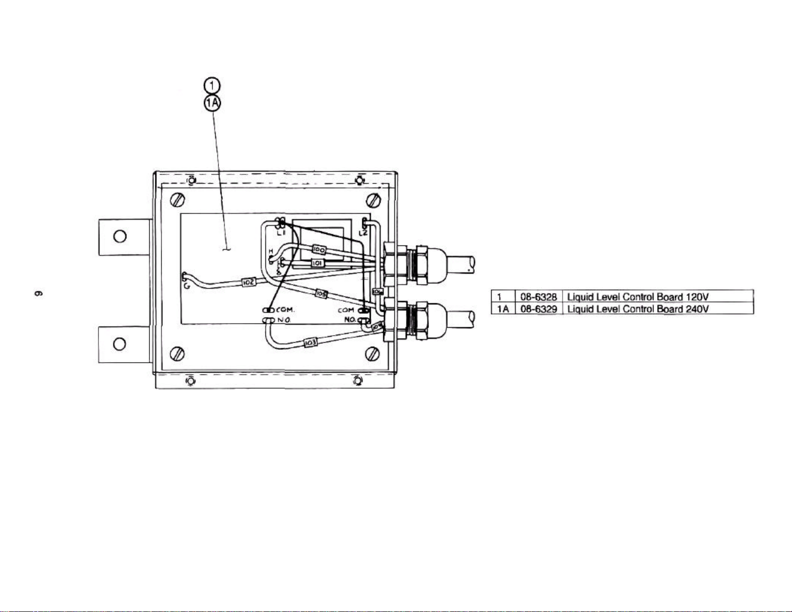
6 08-6328 LIQUID LEVEL CONTROL BOARD
7 10-5570 TERMINAL BLOCK END SECTION (1) REQ'D
7A 10-5503 TERMINAL BLOCK CONTACT SECTIONS (2) REQ'D
8 91 -8666 CONTACTOR CONTROL BOX ASS'Y. 36, 42 & 48KW 3PH
8A 91 -8667 CONTACTOR CONTROL BOX ASS'Y. 36 & 48K W (Export) (4 Wire), 3PH
8B 91-8767 CONTACTOR CONTROL BOX ASS'Y. 18, 24 & 32KW, 3PH, 60 Hz (USA)
8C 91 -8768 CONTACTOR CONTROL BOX ASS'Y. 18KW 1 PH, 60 Hz (USA)
8D 91 -8769 CONTACTOR CONTROL BOX ASS'Y. (Export) 50 Hz, 18, 24, 32KW, 3PH, 4 Wire
REF 91 -8550 WIRING DIAGRAMS FOR 18, 24, 32, 42, & 48KW
9 10-4804 PRESSURE GAUGE
10 08-0034 ANODE (NOT SHOWN, INSIDE STEAM GENERATOR)
24
Page 27

REF: SMALL GENERATOR
WITH CONTACTOR BOX
ITEM # PART NO. DESCRIPTION
1 10-7974 SIGHT GLASS WINDOW
2 91 -3368 REFLECTOR
REF: LARGE GENERATOR
WITH CONTACTOR BOX
REF: ELECTRIC MODULAR BASE STEAM GENERATOR
FINAL ASSY. BOTH LARGE & SMALL
25
 Loading...