

Page 1

MT & LFT 6/10 GALLON SERIES
MODULAR BASE DIRECT STEAM TILTING KETTLES
PARTS AND SERVICE MANUAL
EFFECTIVE SEPTEMBER 4, 2014
The Company reserves the right to make substitution in the event that items specied are not available.
ERRORS: Descriptive and/or typographic errors are subject to correction.
44 Lakeside Avenue, Burlington, Vermont 05401 USA Telephone: (802) 658-6600 Fax: (802) 860-3732
Superseding All Previous Parts Lists.
MARKET FORGE INDUSTRIES
www.mi.com
P/N 14-0326 Rev A (9/14)
Page 2

TABLE OF CONTENTS
REPAIR AND REPLACEMENT ..........................................................3
ILLUSTRATED PART LIST
EXTERIOR ............................................................................5
FAUCET ...............................................................................6
STEAM VALVE .........................................................................7
STEAM TRAP .........................................................................7
NEW STYLE CABINET BASE ...........................................................8
OLD STYLE CABINET BASE ......................................................... 10
SEPTEMBER 4, 2014 2 MT6 & MT10 SERIES DIRECT STEAM KETTLES
Page 3
REPAIR AND REPLACEMENT
MODELS:
• MT6 - Single 6 gallon mounted on an 18” (457mm)
wide x 28” (711mm) tall cabinet base
• MT6G - Single 6 gallon mounted on an 18” (457mm)
wide x 28” (711mm) tall gas boiler
• MT6E - Single 6 gallon mounted on an 18” (457mm)
wide x 28” (711mm) tall electric boiler
• MT10 - Single 10 gallon mounted on an 18”
(457mm) wide x 28” (711mm) tall cabinet base
• MT10G - Single 10 gallon mounted on an 18”
(457mm) wide x 28” (711mm) tall gas boiler
• MT10E - Single 10 gallon mounted on an 18”
(457mm) wide x 28” (711mm) tall electric boiler
• MT6T6 - Two 6 gallon kettles mounted side by side
on an 36” (914mm) wide x 28” (711mm) tall cabinet
base
• MT6T6G - Two 6 gallon kettles mounted side by
side on an 36” (914mm) wide x 28” (711mm) tall gas
boiler
• MT6T6E - Two 6 gallon kettles mounted side by side
on an 36” (914mm) wide x 28” (711mm) tall electric
boiler
• MT10T10 - Two 10 gallon kettles mounted side by
side on an 36” (914mm) wide x 28” (711mm) tall
cabinet base
• LFT6T6 - Two 6 gallon kettles mounted side by side
on an 36” (914mm) wide x 20” (508mm) tall low
boy cabinet base
• LFT10T10 - Two 10 gallon kettles mounted side by
side on an 36” (914mm) wide x 20” (508mm) tall
low boy cabinet base
In the event that the kettle fails to operate correctly, the
difculty should rst be isolated to either the kettle itself
or the steam supply which heats the kettle. While mechanical problems are obvious faults of the kettle, any de-
ciencies in volume and pressure of the steam should be
traced to the steam generator and the cause determined.
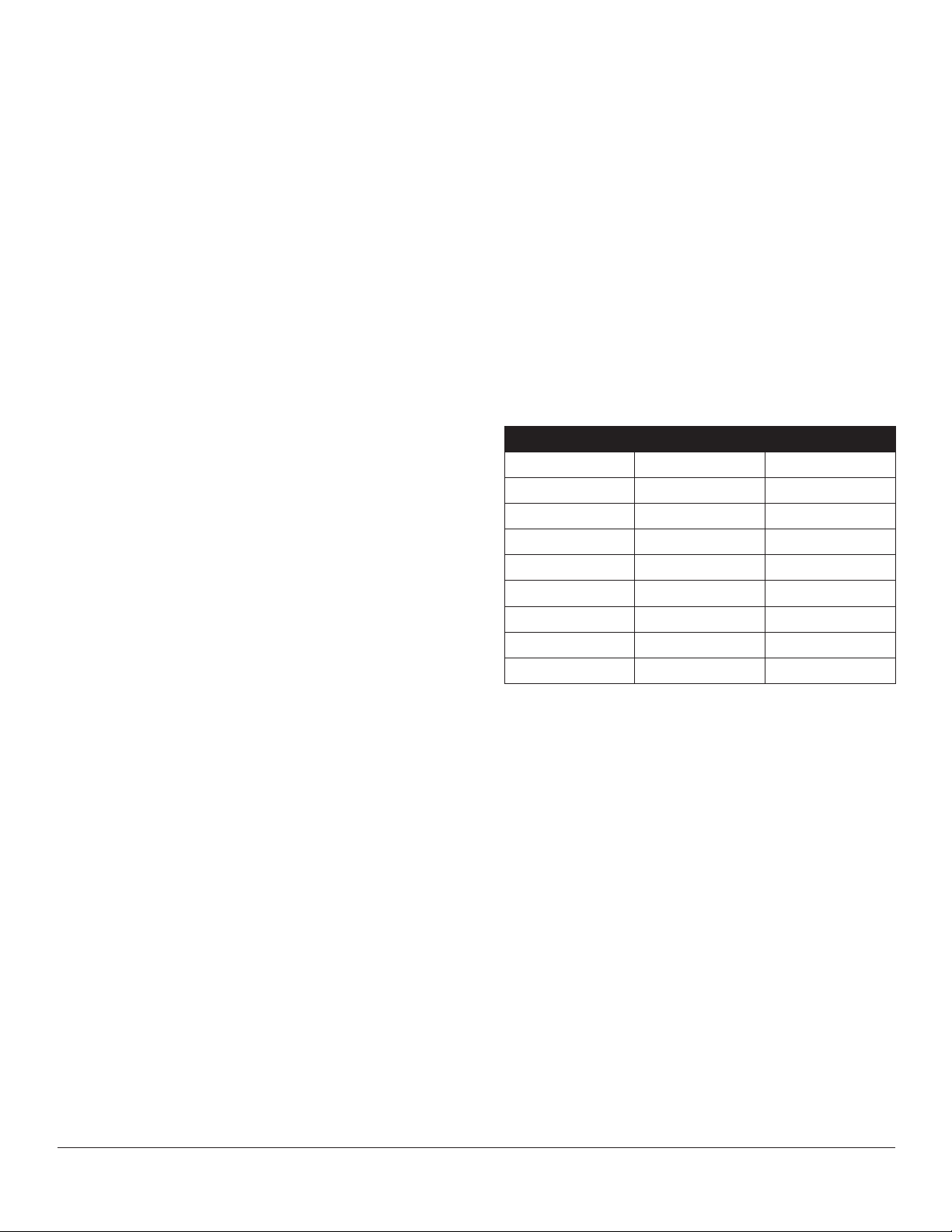
Steam input requirements are listed below. This list recommends delivered boiler horsepower for kettle size and
steam ow.
MODEL BHP STEAM FLOW
MT6 1/3 BHP 15-30 PSI
MT10 1/2 BHP 15-30 PSI
MT6T6 1/3 BHP 15-30 PSI
MT10T6 1/2 BHP 15-30 PSI
MT10T10 1/2 BHP 15-30 PSI
LFT6 1 BHP 15-30 PSI
LFT10 1 BHP 15-30 PSI
LFT10T6 1 BHP 15-30 PSI
LFT10T10 1 BHP 15-30 PSI
• MT10T10G - Two 10 gallon kettles mounted side by
side on an 36” (914mm) wide x 28” (711mm) tall gas
boiler
• MT10T10E - Two 10 gallon kettles mounted side
by side on an 36” (914mm) wide x 28” (711mm) tall
electric boiler
• MT10T6 - One 10 gallon and one 6 gallon kettle
mounted side by side on an 36” (914mm) wide x 28”
(711mm) tall cabinet base
• MT10T6G - One 10 gallon and one 6 gallon kettle
mounted side by side on an 36” (914mm) wide x 28”
(711mm) tall gas boiler
• MT10T6E - One 10 gallon and one 6 gallon kettle
mounted side by side on an 36” (914mm) wide x 28”
(711mm) tall electric boiler
• LFT6 - Single 6 gallon mounted on an 18” (457mm)
wide x 20” (508mm) tall low boy cabinet base
• LFT10 - Single 10 gallon mounted on an 18”
(457mm) wide x 220” (508mm) tall low boy cabi-
net base
CABINET EXTERIOR REMOVAL:
Side and rear panels of all cabinets in which kettles are
mounted are easily removed without the use of tools.
Each panel is grasped at the bottom edge and pulled out
sharply to release it from the panel mounting brackets.
Replacement is completed by pushing panel up under
the cabinet top and pressing in at the bottom until panel
mounting brackets are engaged.
Doors may be removed to improve access to cabinet interior for repairs. The two at head screws, nuts, and holding cabinet hinge are removed to lift the door out. When
doors are remounted, the nal tightened position of hinge
determines the alignment of the door and must be set
with care.
SEPTEMBER 4, 2014 3 MT6 & MT10 SERIES DIRECT STEAM KETTLES
Page 4

REPAIR AND REPLACEMENT
TRUNNION MOUNTED KETTLE DISASSEMBLY:
Trunnion mounted kettles may be removed from the cabinet top for replacement of worn o-rings and lubrication of
trunnion parts.
Disassemble as follows:
1. Disconnect both steam inlet and condensate return
plumbing connected to kettle legs from inside of cabinet.
2. Remove 3/8” nuts and washer used to fasten kettle
legs to cabinet top.
3. Lift kettle with legs attached off of cabinet top.
4. Insert blade of screwdriver in slots of trunnion end
caps and pry off caps.
5. Remove retaining rings from ends of trunnions using
retaining ring pliers.
6. Slip leg and support collar assemblies off of kettle.
7. Remove o-rings and clean off trunnion parts including
insides of support collars attached to legs.
8. Replace o-rings and lubricate trunnion parts with krylon base no. 1325 silicon spray.
9. Reassemble kettle and trunnion by completing step
6 and the 5, and tapping end cap back in place (slot
down) with a rubber mallet.
10. Remount kettle and trunnion assembly on cabinet top
by completing steps 3, 2 and then 1.
SEPTEMBER 4, 2014 4 MT6 & MT10 SERIES DIRECT STEAM KETTLES
Page 5

EXTERIOR
ITEM PART NO. DESCRIPTION QTY
1 97-5008 KNOB 2
2 97-5115 HANDLE 2
2a 97-5116 NUT, ACORN - FOR HANDLE
3 10-5242 STEAM, VALVE, ANGLE 1/2” 2
4 10-3556 FAUCET
5 10-5753 SWING NOZZLE
6 97-5117 END CAP 4
* 97-0662 6 GALLON
97-0663 10 GALLON
8 97-1975 CLEAN-UP PAN
9 CABINET, 36”
- 10-4755 STEAM TRAP
- 97-5122 O-RING, 5/8” ID X 7/8” OD X 1/8” SECT. (NOT SHOWN) 8
- 97-5123 RETAINING RING (NOT SHOWN) 4
10a 97-5118 STANCHION ASS’Y 6 GALLON KETTLE
10b 97-5119 STANCHION ASS’Y 10 GALLON KETTLE
10c 97-5118A STANCHION ASS’Y WITH STEAM CONTROL VALVE 6 GALLON KETTLE
10d 97-5119A STANCHION ASS’Y WITH STEAM CONTROL VALVE 10 GALLON KETTLE
- 97-5120 WASHER FOR STANCHION
- 97-5121 LOCKNUT FOR STANCHION
SEPTEMBER 4, 2014 5 MT6 & MT10 SERIES DIRECT STEAM KETTLES
Page 6

FAUCET
ITEM PART NO. DESCRIPTION
1 10-3108 MOUNTING BASE, RISER
2 10-3357 ADAPTER, 90
3 10-3741 REDUCING, BUSHING
4 91-0887 RISER, 15”
5 10-5753 SWING NOZZLE
6 10-3556 FAUCET
7 10-3684 COMPRESSION FITTING, MALE
8 10-1100 SWIVEL BODY
O
SEPTEMBER 4, 2014 6 MT6 & MT10 SERIES DIRECT STEAM KETTLES
Page 7

STEAM VALVE
ITEM PART NO. DESCRIPTION
1 10-0105 STEAM VALVE HANDLE
2 10-5247 VALVE DISC
3 10-5242 STEAM CONTROL VALVE, ANGLE 1/2”
STEAM TRAP
ITEM PART NO. DESCRIPTION
1 10-4755 STEAM TRAP 1/2”
2 10-4937 THERMOSTAT, STEAM TRAP
SEPTEMBER 4, 2014 7 MT6 & MT10 SERIES DIRECT STEAM KETTLES
Page 8

NEW STYLE CABINET BASE
SEPTEMBER 4, 2014 8 MT6 & MT10 SERIES DIRECT STEAM KETTLES
Page 9

NEW STYLE CABINET BASE
ITEM PART NO. DESCRIPTION
1 98-3681 BOILER, 200K GAS, 24” FRAME
98-3682 BOILER, 200K GAS, 36” FRAME
98-3983 BOILER, 300K GAS, 36” FRAME
98-3684 BOILER, ELECTRIC, 24” FRAME
98-3985 BOILER, ELECTRIC, 36” FRAME
2 98-3998 TOP, PLAIN, 200K GAS BOILER, 24” FRAME
98-3999 TOP, PLAIN, 200 & 300K GAS BOILER, 36” FRAME
98-4000 TOP, PLAIN, ELECTRIC BOILER, 24” FRAME
98-4001 TOP, PLAIN, ELECTRIC BOILER, 36” FRAME
3 98-3995 REAR PANEL, 24” FRAME
98-3996 REAR PANEL, 36” FRAME
4 98-3994 SIDE PANEL, LEFT & RIGHT
5 98-3992 CONTROL (FRONT) PANEL, 24” FRAME
98-3993 CONTROL (FRONT) PANEL, 36” FRAME
6 08-5894 MARKET FORGE NAME PLATE
7 10-2347 STUD RECEIVER
8 98-4015 SUPPORT FRAME, TOP MOUNT, 36” FRAME
94-5124 SUPPORT ANGLE, TOP MOUNT, 24” FRAME
9 08-3822 1/4 Ø FLAT WASHER, ST. ST.
10 08-7840 1/4-20 SERRATED, FLANGED, HEX NUT, ST. ST.
11 10-1770 1/4-20 X 3/4 LG. FLAT HEAD SCREW, ST. ST.
12 98-0593 INNER FLUE, WELD ASSY. 200K GAS, 24” FRAME
91-8936 INNER FLUE, WELD ASSY. GAS, 36” FRAME
13 91-8892 FLUE COVER, FRONT & SIDES, 24” FRAME
91-8938 FLUE COVER, FRONT & SIDES, 36” FRAME
14 91-2713 FLUE COVER, BACK, 36” FRAME
91-8893 FLUE COVER, BACK, 24” FRAME
15 10-1735 #8 X 3/8 LG., PAN HEAD TYPE-A S.M. SCREW
SEPTEMBER 4, 2014 9 MT6 & MT10 SERIES DIRECT STEAM KETTLES
Page 10

OLD STYLE CABINET BASE
SEPTEMBER 4, 2014 10 MT6 & MT10 SERIES DIRECT STEAM KETTLES
Page 11

OLD STYLE CABINET BASE
ITEM PART NO. DESCRIPTION
1 10-2500 WASHER, LOCK ST. 1/4
2 10-0495 STRIP, FEATURE
3 91-8126 TRAY, HOSE
4 91-3348 CHANNEL, REAR FRAME SUPPORT
5 90-3210 BRACKET FOR DOOR MAGNET
6 10-5561 MAGNET, DOOR
7 91-5482 HINGE, LEFT, BOTTOM
8 91-5481 HINGE, RIGHT, BOTTOM
9 90-2663 BRACKET, SIDE AND REAR ST.
10 91-5490 DOOR, ASS’Y, RIGHT HAND
11 91-5484 DOOR, ASS’Y, LEFT HAND
12 91-6132 PANEL, REAR, ALUMINIZED ST.
13 90-2661 PANEL, SIDE, RIGHT & LEFT, ST.
14 10-1928 STUD
15 10-1927 RECEPTACLE
16 10-1929 RETAINER, SPLIT RING
17 10-8057 SCREW RD. HD. ST. 6-32 X 5/8 LG.
18 10-2050 SCREW RD. HD. CAP 3/8-16 X 7/8 LG.
19 10-2503 WASHER, LOCK 3/8
20 10-2141 SCREW RD. HD. CAP 5/16-18 X 1 1/2 LG.
21 10-2511 WASHER, LOCK 5/16
22 10-2405 WASHER, PLAIN ST 5/16
23 10-2147 SCREW HEX. HD. CAP 5/15-18 X 3/4 LG.
24 10-2307 NUT HEX. 5/16-18
25 10-2089 SCREW HEX. HD. CAP 1/4-20 X 7/8 LG.
26 10-2500 WASHER, LOCK ST. 1/4
27 10-2308 NUT HEX. ST. 1/4-20
28 10-1755 SCREW MACHINE, FLAT HD. ST. 1/4-20 X 1 LG.
29 91-3358 GUARD, SPLASH ASS’Y
30 10-0631 FEET, ADJUSTABLE 6”
31 10-0636 FEET, ADJUSTABLE WITH FLANG (NOT SHOWN)
32 10-1869 SCREW FLAT HD. 10-32 X 1/2 LG.
33 10-2505 WASHER, LOCK #10
34 10-2340 NUT, HEX. 10-32
35 10-2143 SCREW HEX. HD. CAP 5/16-18 X 1 1/4 LG.
36 10-1836 SCREW RD. HD. ST. 8-32 X 1/2 LG.
37 10-2521 WASHER, LOCK #8
38 10-2332 NUT, HEX. 8-32
39 10-2400 WASHER, PLAIN 1/4
40 10-1582 BEARING, FLANGE TYPE NYLON
SEPTEMBER 4, 2014 11 MT6 & MT10 SERIES DIRECT STEAM KETTLES
 Loading...