

Page 1

FTM-LE SERIES
SINGLE OR TWIN ELECTRIC STEAM MIXER KETTLE
COMPLETE WITH HYDRAULIC POWER TILT BRIDGE
PARTS AND SERVICE MANUAL
EFFECTIVE SEPTEMBER 19, 2014
The Company reserves the right to make substitution in the event that items specied are not available.
ERRORS: Descriptive and/or typographic errors are subject to correction.
44 Lakeside Avenue, Burlington, Vermont 05401 USA Telephone: (802) 658-6600 Fax: (802) 860-3732
Superseding All Previous Parts Lists.
MARKET FORGE INDUSTRIES
www.mi.com
P/N 14-0378 Rev A (9/14)
Page 2
MAINTENANCE AND REPAIR
Trunnion block bearings, tted with a grease nipple
should be lled with grease every couple of months or
more frequently if so required. They are located in each
console box and support the kettle for ease of tilting. The
segment gear and worm should be greased at the same
time if required. These are located in the tilt console box.
No other general maintenance is required other than ad-
hering to the Cleaning Procedure instructions.
HYDRAULIC SYSTEM SERVICE:
Set up regular schedule for checking the oil temperature,
hydraulic hoses and keeping the equipment clean. A thick
layer of dirt acts as an insulation and prevents the hydraulic system from cooling.
The hydraulic system has been adjusted and tested at
the factory and no adjustment should be needed. If the
unit fails to operate properly, all service work must be performed by a qualied service agent.
A thermostat controlled cooling system has been installed in the hydraulic system to maintain oil tempera-
tures while in operation. The oil is cooled by cold water
owing through a heat exchanger alongside of the oil. A
thermostat activates at 1400 Fahrenheit oil temperature
opening the valve and releasing cold water into the heat
exchanger, cooling the oil.
NOTE: At least twice a year have an authorized service
person clean and service the unit for maximum
performance.
are located at the back of the hydraulic unit. Adjust it
to 800 psi.
3. The speed of the actuator is controlled by an in-line
ow control valve also located at the back of the unit.
There is also a locking set screw provided on the ad-
justing knob.
4. Using the “RAISE/LOWER” tilt switch on the opera-
tor panel, adjust the ow control so that the stroke is
completed at a safe speed.
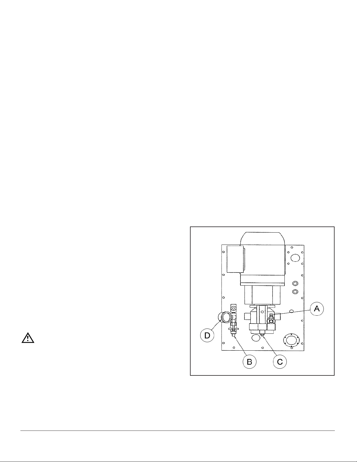
SETTING MIXER SYSTEM PRESSURE:
1. On the operator panel, switch “POWER” to on, “MIXER” to on, and set mixer speed to “STOP”.
2. Turn trim relief stem, item “B”, completely in.
3. Increase the pump pressure by turning “A” inwards,
until gauge “0” reads 1700 psi. The pressure must be
300 psi higher than the pump setting.
4. Adjust trim relief “B” outwards until pressure indicated
on gauge “0” begins to drop.
5. Lock the trim relief “B”.
6. Decrease the pump pressure by turning “A” outwards,
until gauge “0” reads 1400 psi and lock in place.
SETTING THE MIXER SYSTEM FLOW:
1. On the operator panel, switch “POWER” to on, “MIXER” to on, and set mixer speed to “FAST”, the maxi-
mum speed.
2. Increase or decrease ow to maximum rpm as listed,
or less if requested by customer. Turn in “c” to decrease, turn out to increase.
40 Gallon Mixer Kettle 54 RPM
60 Gallon Mixer Kettle 48 RPM
80 Gallon Mixer Kettle 43 RPM
CAUTION
Do not exceed 54 RPM! Decreasing the ow to
less than 10 rpm may over centre the swash
plate and will damage the pump!
Use jam nut to lock adjusting screw when complete.
SETTING THE BRIDGE ACTUATOR:
1. On the operator panel, switch “POWER” to on, “MIXER” to on, and set mixer speed to “STOP”.
2. The pressure reducing valve and associated gauge
SEPTEMBER 19, 2014 2 FTM-LE SERIES ELECTRIC MIXER KETTLES
Page 3

TROUBLESHOOTING
LOW WATER LEVEL:
Proper water level must be maintained within the jacket
for the kettle to operate. Depletion of water may occur
from excessive opening of or leakage through the safety
relief valve. If water is below required operating level, either initially at start-up or during use, the kettle will automatically shut off and the LOW WATER signal light will
come on.
In order for the kettle to operate, the following must be
followed. The kettle must be cool before proceeding with
the following steps. Trip the safety relief valve lever to
relieve all pressure from the kettle jacket. At exterior rear
of kettle jacket remove nut from Air Vent. Insert funnel into
Air Vent opening and slowly add the indicated amount of
clean water for:
PER KETTLE
MODEL
ADD:
FTM-40LE 220 oz. (6.50 liters) 548 oz. (16.2 liters)
FTM-60LE 250 oz. (7.39 liters) 586 oz. (17.33 liters)
FTM-80LE 340 oz. (10.05 liters) 850 oz. (25.12 liters)
IF COMPLETELY
EMPTY, ADD:
6. Reversed rotation.
7. Plugged reservoir lter breather.
8. Oil viscosity too high or operating temperature too
low.
9. Loose or worn pump parts.
10. Pump being driven in excess of rated speed.
11. Air leak at pump shaft seal.
12. Oil level too low and drawing air in through inlet pipe
opening.
13. Air bubbles in intake oil.
PUMP PARTS INSIDE HOUSING FAIL TO OPERATE.
1. Seizure due to lack of oil.
2. Excessive system pressure above maximum pup rating.
3. Excessive torquing of housing bolts.
4. Solid matter being drawn in from reservoir and
wedged in pump.
Replace air vent nut. Follow AIR VENTING INSTRUCTIONS. Continue normal operating procedure of kettle.
EXTREMELY SLOW COOKING TIME:
If the cooking time is abnormally slow then the difculty
may be due to insufcient steam pressure. First deter-
mine that pressure on incoming stream line at kettle is
with in 15 PSI of rated kettle pressure. Note that pressure
approaching the rated kettle pressure are liable to set off
the safety relief valve. If required pressure is available
to kettle, then possibly volume of steam is not sufcient.
Minimum 3/4” pipe size is required to the kettle but if the
steam generating source is at a great distance from the
kettle, larger pipe will be required. Finally, the core of the
steam ow will require disassembly and inspection.
PUMPS: PUMP MAKES EXCESSIVE NOISE.
1. Check for vacuum leaks in the suction line.
2. Check alignment with drive mechanism. Misalign-
ment will cause wear and subsequent high noise
level in operation.
3. Check compatibility of uid being pumped against
manufacturers recommendations.
EXCESSIVE PUMP WEAR:
1. Abrasive dirt in the hydraulic oil being circulated
through the system.
2. Oil viscosity too low.
3. System pressure exceeds pump rating.
4. Pump misalignment.
5. Air being drawn in through inlet of pump.
DIRTY OIL
1. Components not properly cleaned after servicing.
2. Inadequate screening in ll pipe.
3. Air breather left off.
4. Filter dirty or ruptured.
4. Relief or unloading valve set to high.
5. Aeration of uid in reservoir, return lines above uid
level.
SEPTEMBER 19, 2014 3 FTM-LE SERIES ELECTRIC MIXER KETTLES
Page 4

TROUBLESHOOTING
SOLENOID VALVE: FAILS TO OPERATE
1. Is there an electrical signal to the solenoid or oper-
ating device? Is the voltage too low. Check with the
volmeter, test light in an emergency.
2. Has foreign matter jammed the main spool? Remove
en caps and see that main spool is free in its movement. Remember that there will be a quantity of uid
escaping when the cap is removed and provide a
container to catch it.
3. Are solenoids improperly interlocked so that a signal is provided to both units simultaneously? Put test
light on each solenoid lead in parallel and watch for
simultaneous lighting. Check electrical interlock. this
condition probably burns out more solenoids then
any other factor.
4. Is uid media excessively hot? Check for localized
heating which may indicate an internal leak, Check
reservoir temperature and see if it is within machine
specications.
5. Voltage too low? If voltage will not complete the stroke
of alternating current (AC) solenoid will burn out coil.
MOISTURE IN OIL
1. Cooling coils not below uid level.
2. Moisture in cans used to replace uid in tanks.
3. Extreme temperature differential in certain geograph-
ical locations.
FOAMING OIL
1. Return of tank line not below uid level.
2. Fluid contaminated with incompatible foreign matter.
3. Suction leak to pump aerating oil.
6. Signal to both solenoids of a double solenoid valve si-
multaneously. One or both of the solenoids will be unable to complete their stroke and will burn out. Make
certain the electrical signal is interlocked so that this
condition cannot exist.
7. Mechanical damage to leads. Short circuit, open connections, etc.
8. Tight spool or other mechanical parts of the valve be-
ing actuated can prevent the solenoid from completing its stroke and subsequently burning out.
9. Wrong voltage or frequency will either prevent operation, because of inadequate capacity to handle the
load with the lower voltage or burn out the oil, because of improper winding and excessive voltage.
OVERHEATING
1. Continuous operation at relief setting.
a. Stalling under load etc.
b. Fluid viscosity too high or too low.
2. Excessive slippage or internal leakage.
a. Fluid viscosity too low.
3. System relief valve set too high.
4. Power unit ambient temperature too high.
SEPTEMBER 19, 2014 4 FTM-LE SERIES ELECTRIC MIXER KETTLES
 Loading...