

Page 1
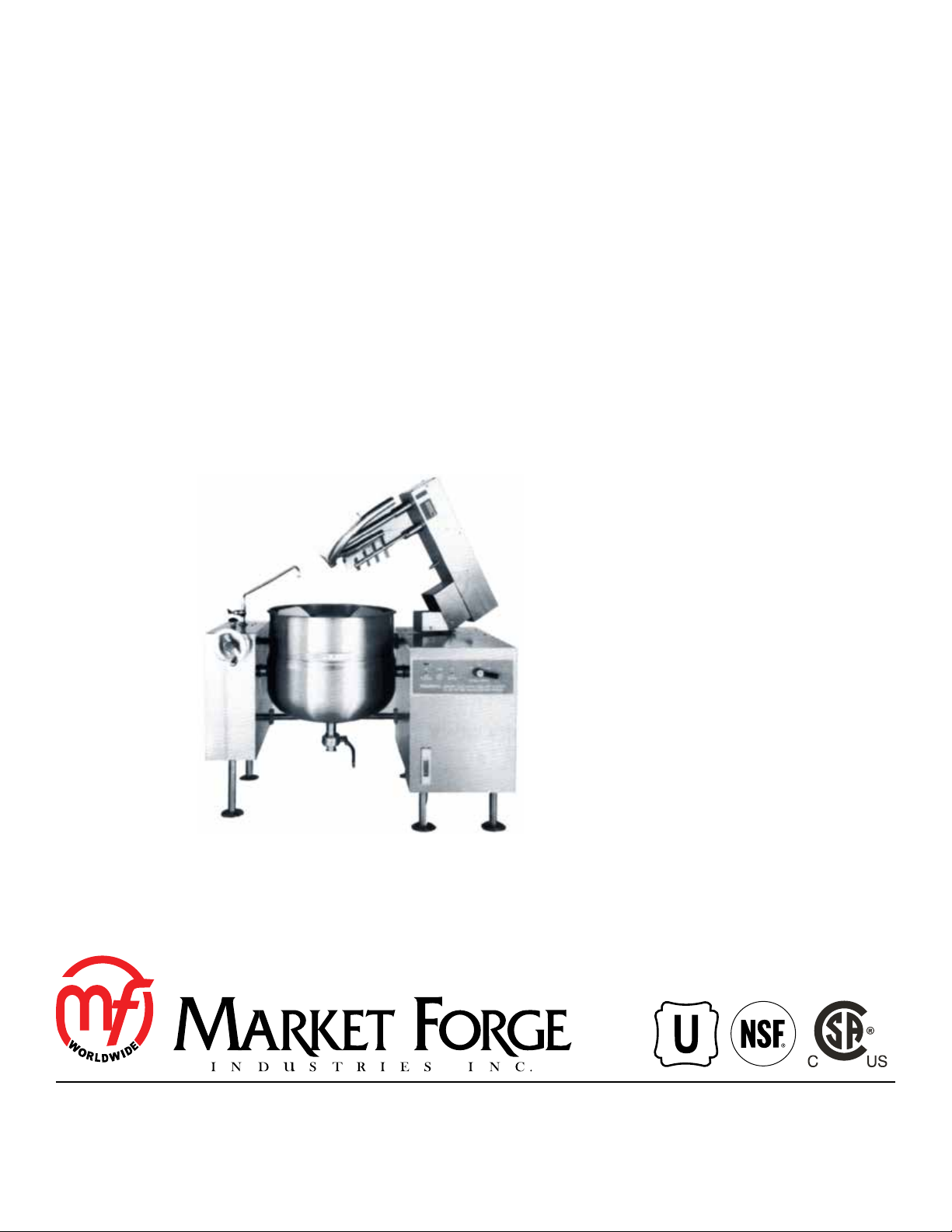
FTM-L SERIES
SINGLE OR TWIN DIRECT STEAM MIXER KETTLE
COMPLETE WITH HYDRAULIC POWER TILT BRIDGE
INSTALLATION - OPERATION - MAINTENANCE
SINGLE MODELS
FTM-40L
FTM-60L
FTM-80L
FTM-100L
TWIN MODELS
FTM-(2)40L
FTM-(2)60L
FTM-(2)80L
FTM-(2)100L
44 Lakeside Avenue, Burlington, Vermont 05401 USA
Telephone: (802) 658-6600 Fax: (802) 864-0183
www.mi.com PN 14-0375 Rev B (2/16)
© 2016 - Market Forge Industries Inc.
Page 2

Your Service Agency’s Address:
Model
Serial number
Oven installed by
Installation checked by
Page 3

IMPORTANT
TABLE OF CONTENTS
WARNING: Improper installation, adjustment, alternation,
service or maintenance can
cause property damage, injury or death. Read the installation, operation and maintenance instructions thoroughly
before installing or servicing
this equipment.
FOR YOUR SAFETY
Do not store or use gasoline or
other ammable vapors or liquids in the vicinity of this or any
other appliance.
The information contained in this
manual is important for the proper installation, use, and maintenance of this oven. Adherence
to these procedures and instructions will result in satisfactory
baking results and long, trouble free service. Please read
this manual carefully and retain
it for future reference.
INSTALLATION
Introduction .............................................................. 2
Service Connections ..................................................... 3
Service Connections ..................................................... 4
Installation Instructions ................................................... 5
OPERATION
Operating Procedure ..................................................... 6
MAINTENANCE
Cleaning ................................................................ 7
ERRORS: Descriptive, typographic or pictorial errors are
subject to correction. Specications are subject to change
without notice.
Page 4

Introduction
DESCRIPTION:
All Market Forge direct connected steam jacketed kettles
pertaining to this manual are direct steam operated pressure vessels of a double wall stainless steel construction forming a steam chamber (jacket) enveloping the
lower two-thirds of the kettle bowl surface. These kettles
operate at a maximum of 35 PSI. Construction shall be
welded stainless steel type 304 satin nish. A double-
wall kettle interior shall form a steam jacket around the
lower 2/3 of the kettle. The bottom of the kettle shall be
of hemispheric design for maximum heat transfer. (316
stainless steel liner is standard on 40 gallon for high-acid
content products).
The mixer is a variable-speed unit powered by a 5 hp
electric motor driving a hydraulic pump. Two agitators
shall be included: a primary stainless steel scraper/
agitator, and a secondary high-speed mixer. Both agitators shall be removable for cleaning, and no tools will
be required for removal. The console front to have the
main power switch, mixer lift switch, and variable speed
control.
The tubular legs shall be constructed of stainless steel
pipe tted with four-hole adjustable anged feet for
securing to the oor. A sealed stainless steel tilt mecha-
nism shall permit the kettle to tilt forward a full 90° for
complete emptying. The tilt mechanism shall be selflocking for positive stop action.
The bridge is constructed of 10-gauge stainless steel
and contains two heavy-duty hydraulic motors to drive
the agitators. The bridge shall be power tilt, and swing
140° out of the way for kettle tilting or cleaning.
CAPACITIES:
• FTM-40L - one 40 gallon (152 liters) kettle
• FTM-60L - one 60 gallon (227 liters) kettle
• FTM-80L - one 80 gallon (303 liters) kettle
• FTM-100L - one 100 gallon (380 liters) kettle
• FTM-(2)40L - two 40 gallon (152 liters) kettles
• FTM-(2) 60L - two 60 gallon (227 liters) kettles
• FTM-(2) 80L - two 80 gallon (303 liters) kettles
• FTM-(2) 100L - two 100 gallon (380 liters) kettles
OPERATION WILL BE BY:
2
Direct steam at 15 to 35 PSI (1.0 to 2.46 kg/cm
1/3 BHP required. Over 35 PSI (2.46 kg/cm2), a pressure-reducing valve is required. Standard hydraulic
power supplies are either of the following:
208 Volt, 3 Ph, 60 Hz
240 Volt, 3 Ph, 60 Hz
).
INSTALLATION
2
Page 5

SINGLE KETTLES
Service Connections
SERVICE CONNECTIONS
S* Steam Supply - 3/4” (19mm) IPS for incoming steam at 15-50 PSI
(1.0-3.5kg/cm2)
CW Cold Water - 1/2” (13mm) O.D. tubing to fill faucet (optional).
CR Optional Condensate Return - 1/2” (13mm) IPS condensate return
from kettle may be connected to condensate return line.
ELECTRICAL CHARACTERISTICS
VOLTAGE PHASE AMPS HZ
208 (197-219) 3 14 60
240 (220-240) 3 14 60
480 (360-500) 3 7 60
EC Electrical Connection - Mixer motor 5 HP
*Pressure reducing valve is required if incoming pressure exceeds 35 PSI (2.46 kg/cm2). Pressure relief valve must be installed in the
incoming steam line if not connected to a Market Forge gas or electric steam generator. Valve is supplied on request at no extra cost.
NOTE: PVC and CPVC pipe are not acceptable materials for drains.
DIMENSIONS
MODEL A B C D E F G
FTM-40L 26 [660] 62 [1575] 45.5 [1156] 55 [1397] 75.63 [1921] 14.75 [375] 56 [1422]
FTM-60L 29.5 [749] 65 [1651] 49 [1245] 58.5 [1486] 80 [2032] 19 [483] 58 [1473]
FTM-80L 33 [838] 67.75 [1721] 49 [1245] 58.5 [1486] 80 [2032] 19 [483] 60 [1524]
FTM-100L 37.13 [943] 70.5 [1791] 49 [1245] 58.5 [1486] 85 [2159] 19 [483] 62 [1575]
B
11
[279]
5 [129]
2 [51]
10.25
[260]
8.625 [219]
4 [102]
EC
2.25 [57]
6 [152]
WO
WI
DIMENSIONS ARE IN INCHES [MM]
30 [762]
CW
E
20.50
[521]
S
S
9 [229]
CW
F
10 [254]
14 [356]
A
CR
EC
8 [203]
CR
D
38.25 [971]
4 [102] MIN.
C
G (APPROX.)
FLANGED FOOT DETAIL
4 EQUALLY SPACED
7/16” [11mm] DIA. HOLES
ON 3” [76mm] B.C.
Figure 1
3
INSTALLATION
Page 6

Service Connections
G (APPROX.)
TWIN KETTLES
SERVICE CONNECTIONS
S* Steam Supply - 3/4” (19mm) IPS for incoming steam at 15-50 PSI
(1.0-3.5kg/cm2)
CW Cold Water - 1/2” (13mm) O.D. tubing to fill faucet (optional).
CR Optional Condensate Return - 1/2” (13mm) IPS condensate return
from kettle may be connected to condensate return line.
ELECTRICAL CHARACTERISTICS
VOLTAGE PHASE AMPS HZ
208 (197-219) 3 14 60
240 (220-240) 3 14 60
480 (360-500) 3 7 60
EC Electrical Connection - Mixer motor 5 HP
*Pressure reducing valve is required if incoming pressure exceeds 35 PSI (2.46 kg/cm2). Pressure relief valve must be installed in the
incoming steam line if not connected to a Market Forge gas or electric steam generator. Valve is supplied on request at no extra cost.
NOTE: PVC and CPVC pipe are not acceptable materials for drains.
DIMENSIONS
MODEL A B C D E F G
FTM-(2)40L 26 [660] 102 [2591] 45.5 [1156] 55 [1397] 75.63 [1921] 14.75 [375] 56 [1422]
FTM-(2)60L 29.5 [749] 108 [2743] 49 [1245] 58.5 [1486] 80 [2032] 19 [483] 58 [1473]
FTM-(2)80L 33 [838] 116 [2996] 49 [1245] 58.5 [1486] 80 [2032] 19 [483] 60 [1524]
FTM-(2)100L 35.5 [902] 121 [3073] 49 [1245] 58.5 [1486] 85 [2159] 19 [483] 63 [1600]
B
8 [203]
CW
8.625 [219]
10 [254]
8 [203]
S
4 [102]
EC
CR
2.25 [57]
6 [152]
CR
WO
WI
CW
S
10.25 [260]
11 [279]
30
[762]
38.25
[971]
DIMENSIONS ARE IN INCHES [MM]
FLANGED FOOT DETAIL
4 EQUALLY SPACED
7/16” [11mm] DIA. HOLES
ON 3” [76mm] B.C.
4 [102] MIN.
CW
E
S
F
INSTALLATION
EC
CR
A
2 PL
CW
S
2 [51]
Figure 2
4
3.5 [89]
7 [179]
D
C
Page 7

Installation Instructions
1. Select a location to provide drainage for kettle
pour path when tilted and for buttery valve if so
equipped.
2. Mark hole location on the oor through ange feet.
Move kettle to drill holes.
3. At marked hole locations, drill holes and insert
expansion shields to accommodate 5/16” size lag
bolts.
4. Reposition kettle, level kettle by making necessary
adjustments to adjustable ange feet.
5. Bolt down kettle and seal the anged feet with a
Silastic or other equivalent sealing compound. Seal-
ant must be applied no only to the bolt heads but
also around the anges making contact with the oor
surface to fulll NSF requirements.
6. Connect steam line (3/4” pipe size) to the steam inlet, make sure there is a steam control valve strainer
fairly conveniently placed near the kettle.
7. Connect kettle condensate return line to a drain or
to a boiler return line. Each kettle lines must have a
suitable steam trap. Boiler return lines must have a
check valve.
8. Safety relief valve on kettle must not be plugged as it
is set to relieve excess pressure in the kettle.
9. If incoming steam pressure is greater than kettle
maximum operating pressure then a pressure reducing valve must be installed in the line.
10. If large amounts of water accumulate in the steam
line it will be necessary to install one or more ball
oat traps in the line to eliminate water.
11. A steam line pressure gauge is also recommended
to determine the actual amount of steam coming to
the kettle.
12. Make electrical connection for hydraulic console as
per electrical data plate on the unit.
WARNING
When making electrical connection ensure
that motor rotates in correct direction. pump
may be damaged if incorrect.
13. Check for proper operation.
5
INSTALLATION
Page 8

Operating Procedure
OPERATING PROCEDURE
1. If kettle has draw-off valve, close it.
2. Fill kettle with product to desired level.
3. Slowly turn the steam control valve on to full open
position (counterclockwise).
4. The water or food should boil 3-4 minutes per gallon. If it does not, then incoming pressure should be
checked to determine that it is adequate to operate
the kettle efciently.
5. Regulate steam control valve depending on type of
food being prepared.
6. When food is cooked, turn off steam, remove food
and clean kettle immediately to prevent residue from
drying on kettle bowl surface.
OPERATING MIXER UNIT
Power to operate the mixer unit is controlled by the “main
power switch” located on the left side of the control panel.
Place switch in “on” position. Ensure that “mixer speed
control” is set to the “stop” position.
Set the “mixer switch”, located next to the main power
switch to the “on” position. Note that the agitators should
not be turning. The speed control has four basic settings
which are, stop, slow, medium and fast.
Set the speed control to the “slow” position and observe
the agitators will begin to turn.
CAUTION
NEVER PLACE HANDS INSIDE KETTLE WHEN
THE AGITATORS ARE IN MOTION.
Increasing the speed setting on the control will increase
the speed at which the agitators turn.
NOTE: Always start agitators at the slow speed and then
gradually increase to the desired speed to avoid
splashing or throwing the product over edge of
kettle.
Push the “tilt” switch to the “raise” position a nd hold.
Bridge will raise to maximum height. Bridge will stop at
any position the tilt switch is released and will remain until
the switch is pushed to wither raise or lower.
NOTE: The bridge is equipped with a safety which pre-
vents turning of the agitators, regardless of the
mixer switch, or speed control settings. Agitators will not engage unless the bridge is lowered
so that the guide pin rests fully in the guide pin
bracket on the side of the kettle.
REMOVAL OF AGITATORS
The agitators are removable without tools, for ease of
cleaning. To remove raise bridge as described in “Raising Mixer Bridge” and swing clear of kettle. Grasp shaft
of large agitator, push up and turn to disengage lock pin.
Pull straight down on agitator. Remove the small agitator
in the same manner. If it is necessary to remove scrapers
blades for cleaning purposes, remove the pin at the end
of the mounting shaft and then slide the scraper blade off
the shaft.
EXTREMELY SLOW COOKING TIME:
If the cooking time is abnormally slow then the difculty
may be due to insufcient steam pressure. First deter-
mine that pressure on incoming stream line at kettle is
with in 15 PSI of rated kettle pressure. Note that pressure approaching the rated kettle pressure are liable
to set off the safety relief valve. If required pressure is
available to kettle, then possibly volume of steam is not
sufcient. Minimum 3/4” pipe size is required to the kettle
but if the steam generating source is at a great distance
from the kettle, larger pipe will be required. Finally, the
core of the steam ow will require disassembly and
inspection.
RAISING MIXER BRIDGE
Tilt kettle for emptying or to clean agitators, the mixer
bridge will tilt hydraulically upward and manually swing
to clear the kettle. To do this, rst turn “speed control” to
“stop” and then turn mixer switch to “off”.
NOTE: Mixer agitator arms must be stopped at 90O to the
mixer bridge before raising the bridge. If the agitator arms do not stop in this position when speed
selector is set to stop, the “jog” the selector on
and off to achieve this position.
OPERATION
6
Page 9

Cleaning & Preventative Maintenance
DAILY CLEANING
1. Ensure that steam supply is “off”.
2. Pre-rinse inside of kettle thoroughly and drain to remove any food.
3. Using a nylon brush, clean kettle with a mild detergent and warm water rinse. Never use steel wool or
scouring pads as it will scratch the stainless steel.
4. Tilt kettle fully to open the tangent draw-off valve if
one is provided to allow soap and water solution to
drain. Rinse with clean water.
5. On kettles equipped with a draw-off valve, by hand
turn the large hex nut counterclockwise until ti is completely disengaged from thread. Grasp knob to valve
and slowly pull out valve stem and disc. Do not allow disc to come in contact with hard surfaces since
damage to disc may occur and result in valve leakage. Wash the valve stem, disc and handle. Insert
nylon brush with detergent into interior of valve body
and tangent draw-off tube and brush vigorously. Replace valve steam assembly and engage hex nut fully
by hand. Flush kettle with clean warm water. Leave
valve open when kettle is not in use.
WARNING
It is not recommended to use cleaning agents
that are corrosive. Use of cleaning agents that
contain chloride, acids or salts are corrosive
and may cause pitting and corrosion when
used over a period of time; this will reduce
the life of the unit. Should pitting or corrosion
occur this is not covered by warranty. Follow
the recommended cleaning instructions. Use
a mild detergent, warm water and rinse thoroughly.
RESERVOIRS
Maintain oil level at all times. The oil should be checked
after the rst 100 hours and verify that the class of oil
meet the requirements of the pump being used. Change
the oil every 1,000 to 2,000 hours depending on the application and operating environment.
HYDRAULIC SYSTEM
1. Set up regular schedule for checking the oil temperature, appearance, smell and feel. Change oil as
recommended by the equipment manufacturer.
2. Be prompt about removing, checking and repairing
or replacing valves, pumps or other components that
are running hot.
3. Break in new components gradually. New, closetting parts expand at different rates and are especially prone to seize when they get too hot.
4. Start a cold pump or motor on hot oil by jogging
just enough to draw the hot oil into the component.
Then wait a few minutes to allow the temperatures to
equalize in all the pumps parts. Repeat until the temperature on the outside of the pump ios the same as
that on the piping.
5. Keep your equipment clean. A thick layer of dirt acts
as insulation. It will prevent the hydraulic system
from extracting heat.
6. On hot days and in hot climates check and change
the oil more frequently. Be sure to use an oil recommended for hot weather operation by the oil supplier.
PREVENTATIVE MAINTENANCE
FILTERS
Change or clean as required or as indicated on lters supplied with visual indicators.
Filers must be maintained. The key to good ltration is
lter maintenance. A machine may be equipped with the
best lters available and they may be positioned in the
systems when they do the most good; but, if the lters are
not take care of and cleaned when dirty will be a waste
of time and money. A lter which get dirty after one day of
operation and if cleaned 29 day later gives you 29 days of
non-ltered uid.
7
MAINTENANCE
 Loading...