

Page 1
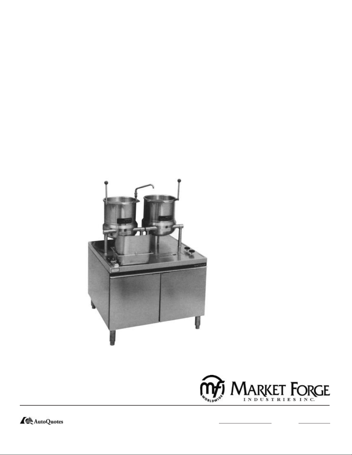
OWNER’S MANUAL
DIRECT KETTLE
MODEL:
FT-6
•
Form Number: REV:A 05/06
Printed in U.S.A. 35 Garvey Street l Everett l MA l 02149
Tel: (617) 387-4100 l Fax: (617) 387-4456 l Outside MA Fax: (800) 227-2659
E-Mail: CUSTSERV@mi.com l Website: www.mi.com
Page 2

TABLE OF CONTENTS
INTRODUCTION ................................................................................................................
OPERATING .......................................................................................................................
MAINTENANCE ..................................................................................................................
REPAIR AND REPLACEMENT ...........................................................................................
PARTS LIST ........................................................................................................................
1
2
2
3
4-8
i
Page 3

OPERATING
Consult boiler information or instructions plate and
copmplete all start-up instructions.
OPERATE KETTLE AS FOLLOWS:
Check pressure gauge of steam supply to ensure
1.
steam input is at approximately 15 PSI (1.0kg/cm2)
to a maximum of 50 PSI (3.5 kg/cm2). For direct
connected steam, turn on external steam supply
valve.
Load kettle with food to be cooked.
2.
Add water for cooking by turning swing nozzel over
3.
kettle and using combination faucet.
Turn steam valve to full counterclockwise position
4.
to allow steam to ow into jacket. Wait until food
reaches desired temperature.
Adjust subsequent cooking temperature by turning
5.
steam control valve. Turn clockwise to reduce heat
(steam ow) and counterclockwise to increase heat
(steam ow).
Close steam control valve and remove food from
6.
kettles as soon as cooking is complete to prevent
overcooking. (OLD Style - Place food pan under kettle
being used and tip kettle forward using kettle handle.
NEW Style - Attach splash gaurd to food pan. Place
food under kettle being used and tip kettle forward using
kettle handle). (NOTE: Before tilting kettle, ensure that
a.) Swing nozzle is rotated clear of kettle. b.) Kettle is
not full. If kettle is full ladle out 2 gallons of contents by
hand.)
Complete Cleaning Procedure (see below).
7.
MAINTENANCE
GENERAL:
This section contains both preventive and corrective
maintenance information. Preventive maintenance
may be performed bt maintenance personnel at the
establishment in which the kettle is installed. It is remommended that user personnel never attemot to make
repairs or replacements to the equipment without the
assistance of authorized services. Assistence in service methods or a current directory of authorized service agencies may be obtained from Market Forge (see
page 1 for contact information).
PREVENTIVE MAINENANCE:
The most important preventive maintenance operation on the steam jacketed kettle is the cleaning procedure. Cleaning should be faithfully completed at the
end of each day, Including cabinet doors, counter-top,
xtures, kettle lid, etc, should be washed and rinsed to
remove all food spills.
CLEANING PROCEDURE AS FOLLOWS:
Fill kettle with water and mild detergent immeddi-
1.
ately after removing food from the kettle.
Remove food soil using a nylon brush. (NOTE: Nev-
2.
er scrape the inside of the kettle with metal tools, steel
scouring pads or abrasive cleaners. Scratches will result
which ruin the general apperance of the kettle and make
it harder to clean and maintain in a sanitary condition).
Lossen food which is stuck to the kettle by allow-
3.
ing it to soak. Also, a small amount of steam may
help.
Place clean-Up pan under kettle being washed by
4.
inserting clan-up pan drain extension into countertop drain openiong. (NEW Style - Attach splash guard
to clean-Up pan). Tilt kettle to pour out wash water.
Rinse kettle with hot water.
5.
Thoroughly wash and rinse kettle exteripr and cabi-
6.
net exterior.
Thoroughlt dry unit.
7.
2
Page 4

REPAIR AND REPLACEMENT
TRUNNION MOUNTED KETTLE DISASSEMBLY:
Trunnion mounted kettles may be removed from the
cabinet top for replacement of worn o-rings and lubrication of trunnion parts.
Disassemble as follows:
Disconnect both steam inlet and condensate return
plumbing connected to kettle legs from inside of
cabinet.
Remove 3/8” nuts and washer used to fasten kettle
legs to cabinet top.
Lift kettle with legs attached off of cabinet top.
Insert blade of screwdriver in slots of trunnion end
caps and pry off caps.
Remove retaining rings from ends of trunnions using retaining ring pliers.
Slip leg and support collar assemblies off of ket-
tle.
Remove o-rings and clean off trunnion parts including insides of support collars attached to legs.
Replace o-rings and lubricate trunnion parts with
krylon base no. 1325 silicon spray.
Reassemble kettle and trunnion by completeing
step 6 and the 5, and tapping end cap back in place
(slot down) with a rubber mallet.
Remount kettle and trunnion assembly on cabinet
top by completeing steps 3, 2 and then 1.
1.
2.
3.
4.
5.
6.
7.
8.
9.
10.
In the event that the kettle fails to operate correctly,
the difculy should rst be isolated to eother the kettle
itself or the steam supply which heats the kettle. While
mechanical problems are obvious faults of the kettle,
any deciences in volume and pressure of the steam
should be traced to the steam generator and the cause
determined. Steam input requirements are listed below. This list recommends delivered boiler horsepower
for kettle size and steam ow.
3
Page 5

PARTS LIST
Fig. 1 MT-6T6
ITEM PART
NO. NO. DESCRIPTION QTY.
1 97-5008 KNOB 2
2 97-5115 HANDLE 2
2a 97-5116 NUT, ACORN - FOR HANDLE
3 10-5242 STEAM, VALVE, ANGLE 1/2” (SEE FIG. 5) 2
4 10-3556 FAUCET (SEE FIG. 5)
5 10-5753 SWING NOZZLE (SEE FIG. 5)
6 97-5117 END CAP 4
* 97-0662 6 GALLON
97-0663 10 GALLON
8 97-1975 CLEAN-UP PAN
9 CABINET, 36” (SEE FIG. 5)
- 10-4755 STEAM TRAP (SEE FIG. 4)
- 97-5122 O-RING, 5/8” ID X 7/8” OD X 1/8” SECT. (NOT SHOWN) 8
- 97-5123 RETAINING RING (NOT SHOWN) 4
10a 97-5118 STANCHION ASS’Y 6 GALLON KETTLE
10b 97-5119 STANCHION ASS’Y 10 GALLON KETTLE
10c 97-5118A STANCHION ASS’Y WITH STEAM CONTROL VALVE 6 GALLON KETTLE
10d 97-5119A STANCHION ASS’Y WITH STEAM CONTROL VALVE 10 GALLON KETTLE
- 97-5120 WASHER FOR STANCHION
- 97-5121 LOCKNUT FOR STANCHION
4
Page 6

PARTS LIST
Fig. 2 Faucet
ITEM PART
NO. NO. DESCRIPTION
1 10-3108 MOUNTING BASE, RISER
2 10-3357 ADAPTER, 90
3 10-3741 REDUCING, BUSHING
4 91-0887 RISER, 15”
5 10-5753 SWING NOZZLE
6 10-3556 FAUCET
7 10-3684 COMPRESSION FITTING, MALE
8 10-1100 SWIVEL BODY
O
5
Page 7

PARTS LIST
Fig. 3 Steam Valve
ITEM PART
NO. NO. DESCRIPTION
1 10-0105 STEAM VALVE HANDLE
2 10-5247 VALVE DISC
3 10-5242 STEAM CONTROL VALVE, ANGLE 1/2”
Fig. 4 Steam Trap
ITEM PART
NO. NO. DESCRIPTION
1 10-4755 STEAM TRAP 1/2”
2 10-4937 THERMOSTAT, STEAM TRAP
6
Page 8

PARTS LIST
Fig. 5 Cabinet Base, 36”
7
Page 9

PARTS LIST
ITEM PART
NO. NO. DESCRIPTION
1 10-2500 WASHER, LOCK ST. 1/4
2 10-0495 STRIP, FEATURE
3 91-8126 TRAY, HOSE
4 91-3348 CHANNEL, REAR FRAME SUPPORT
5 90-3210 BRACKET FOR DOOR MAGNET
6 10-5561 MAGNET, DOOR
7 91-5482 HINGE, LEFT, BOTTOM
8 91-5481 HINGE, RIGHT, BOTTOM
9 90-2663 BRACKET, SIDE AND REAR ST.
10 91-5490 DOOR, ASS’Y, RIGHT HAND
11 91-5484 DOOR, ASS’Y, LEFT HAND
12 91-6132 PANEL, REAR, ALUMINIZED ST.
13 90-2661 PANEL, SIDE, RIGHT & LEFT, ST.
14 10-1928 STUD
15 10-1927 RECEPTACLE
16 10-1929 RETAINER, SPLIT RING
17 10-8057 SCREW RD. HD. ST. 6-32 X 5/8 LG.
18 10-2050 SCREW RD. HD. CAP 3/8-16 X 7/8 LG.
19 10-2503 WASHER, LOCK 3/8
20 10-2141 SCREW RD. HD. CAP 5/16-18 X 1 1/2 LG.
21 10-2511 WASHER, LOCK 5/16
22 10-2405 WASHER, PLAIN ST 5/16
23 10-2147 SCREW HEX. HD. CAP 5/15-18 X 3/4 LG.
24 10-2307 NUT HEX. 5/16-18
25 10-2089 SCREW HEX. HD. CAP 1/4-20 X 7/8 LG.
26 10-2500 WASHER, LOCK ST. 1/4
27 10-2308 NUT HEX. ST. 1/4-20
28 10-1755 SCREW MACHINE, FLAT HD. ST. 1/4-20 X 1 LG.
29 91-3358 GUARD, SPLASH ASS’Y
30 10-0631 FEET, ADJUSTABLE 6”
31 10-0636 FEET, ADJUSTABLE WITH FLANG (NOT SHOWN)
32 10-1869 SCREW FLAT HD. 10-32 X 1/2 LG.
33 10-2505 WASHER, LOCK #10
34 10-2340 NUT, HEX. 10-32
35 10-2143 SCREW HEX. HD. CAP 5/16-18 X 1 1/4 LG.
36 10-1836 SCREW RD. HD. ST. 8-32 X 1/2 LG.
37 10-2521 WASHER, LOCK #8
38 10-2332 NUT, HEX. 8-32
39 10-2400 WASHER, PLAIN 1/4
40 10-1582 BEARING, FLANGE TYPE NYLON
8
 Loading...