

Page 1
OWNER’S MANUAL
Form Number: S-2337 B 09/12
Printed in USA 35 Garvey Street, Everett, MA 02149
Telephone (617) 387-4100, (866) 698-3188, Fax (617) 387-4456, (800) 227-2659
custserv@mfii.com, www.mfii.com
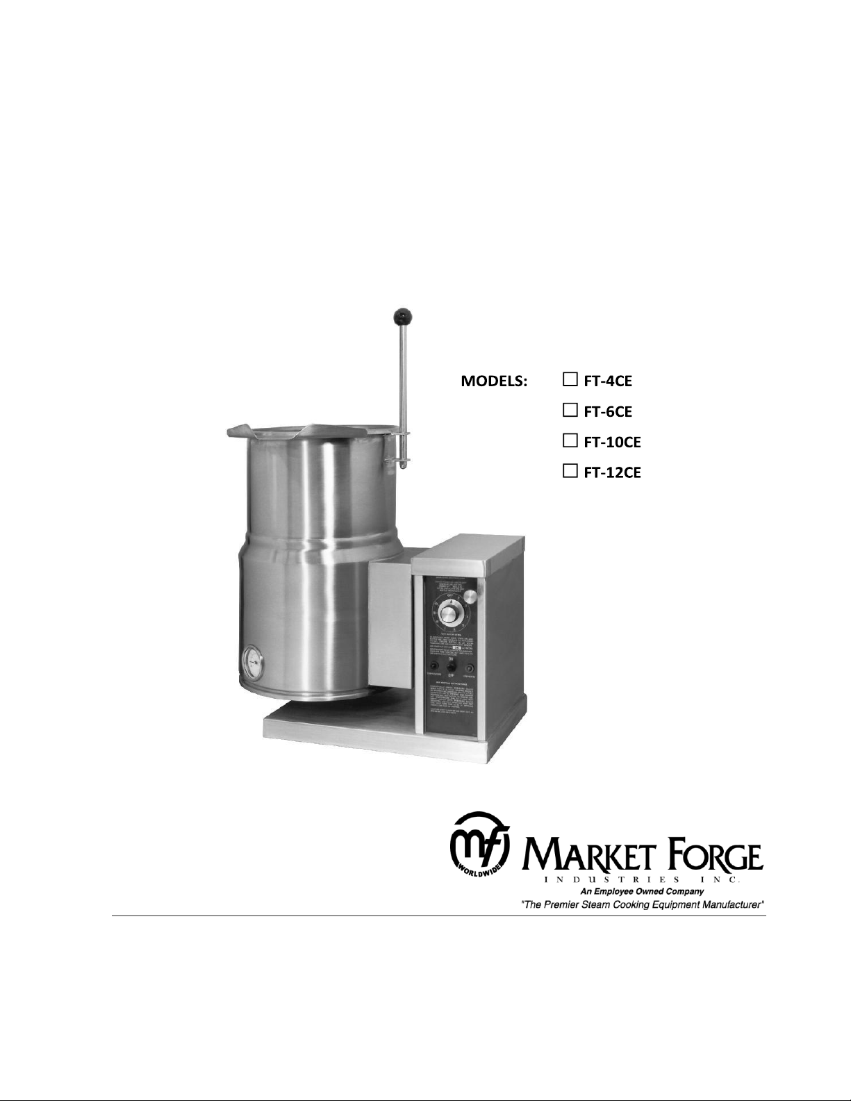
SELF-GENERATING STEAM JACKETED COUNTER TILTING KETTLES
Page 2

Contents
IMPORTANT NOTES ......................................................................................................................................1
INTRODUCTION .............................................................................................................................................1
Description: ................................................................................................................................................ 1
Basic Functioning: ....................................................................................................................................... 2
Service: ....................................................................................................................................................... 2
Product Service Department ................................................................................................................. 2
INSTALLATION ...............................................................................................................................................3
Service Connections
.................................................................................................................................. 3
Electrical Characteristics
Installation Instructions:
........................................................................................................................... 3
......................................................................................................................... 4
Wiring Diagrams ......................................................................................................................................... 5
OPERATION INSTRUCTIONS
.................................................................................................................... 10
Kettle Controls ..................................................................................................................................... 10
Thermostat Settings ............................................................................................................................. 11
Tilting Instructions .................................................................................................................................... 11
MAINTENANCE
Cleaning Instructions
......................................................................................................................................... 12
.............................................................................................................................. 12
TROUBLESHOOTING ................................................................................................................................... 13
General
..................................................................................................................................................... 13
Low Water Level ....................................................................................................................................... 13
Venting Instructions ................................................................................................................................. 13
ILLUSTRATED PARTS LIST
Top View
.................................................................................................................................................. 15
......................................................................................................................... 15
Top View Parts List
Front View
............................................................................................................................................... 17
Front View Parts List
Tilting Mechanism
............................................................................................................................. 15
.......................................................................................................................... 18
................................................................................................................................... 20
Tilting Mechanism Parts List
MATERIAL SAFETY DATA SHEET
.............................................................................................................. 20
.............................................................................................................. 21
Page 3
IMPORTANT NOTES
Do not attempt to operate this unit in the event of a power failure.
Keep the appliance area free and clear from combustibles. Do not obstruct the flow of combustion and
ventilation air. Adequate clearances must be maintained for servicing and proper operation.
This is the safety alert symbol. It is used to alert you to potential personal injury hazards. Obey all
safety messages that follow this symbol to avoid possible injury or death.
WARNING:
Improper installation, operation, adjustment, alteration, service or maintenance can cause property
damage, injury or death. Read the installation, operating and maintenance instructions thoroughly
before installing, operating or servicing this equipment.
This manual should be retained for future reference.
This manual should be read thoroughly and all instructions followed carefully.
INTRODUCTION
THIS OWNERS MANUAL CONTAINS DESCRIPTIVE INFORMATION, INSTALLATION, OPERATING
INSTRUCTIONS, MAINTENANCE AND TROUBLE-SHOOTING INFORMATION FOR MODELS FT-4CE,
FT-6CE, FT-10CE & FT-12CE STEAM-JACKETED KETTLES. PARTS LISTS ARE ALSO INCLUDED IN
WHICH EACH REPLACEABLE PART IS IDENTIFIED AND SHOWN IN AN ACCOMPANYING
ILLUSTRATION.
Description:
Market Forge Models FT-4CE (4-gallon capacity), FT-6CE (6 gallon capacity), FT-10CE (10 gallon capacity)
and FT-12CE (12 gallon capacity) are electrically powered, self-contained, counter-top, tilting Kettles. Each
model has a jacket of double-wall construction forming a sealed reservoir around the lower 2/3 of the
kettle.
The reservoir is charged with water and anti-freeze solution. Kettles are equipped with a removable
electric heating element and controls, including a low water cutoff device for protection of the heating
element. Both models are of identical construction, except for kettle size and element heating capacity.
1
Page 4

Basic Functioning:
Self-contained kettles operate by generating steam in the kettle reservoir. The sequence of operation is
as follows:
1. Operator flips the power switch to the ON position and sets the temperature control dial at the
desired setting from 1 to 10 (90°F to 300°F, 32°C to 149°C, jacket temperature).
2. Control circuit is normally completed to the temperature controller if the following conditions
exist:
a. Water level in kettle reservoir is adequate to prevent circuit interruption by the low
water cutoff device. An activated cutoff is indicated by the amber low water light turning
on, and the heating element shutting off.
b. Kettle is in vertical position with circuit completed through the tilt interlock switch (Micro
switch).
3. Thermostatic control contacts close to energize contactor coils.
4. Power is supplied to the elements through closed power contactors.
5. As the temperature of water rises in the kettle reservoir increase in steam pressure is indicated on
the pressure gauge.
6. When the temperature of steam in the reservoir reaches the setting shown on the temperature
control dial the temperature controller opens to break the contacts and shut off the heating
element. ON/OFF cycles will occur as required to maintain temperature control. See operation
section.
Service:
Required service both preventive and corrective is explained in operation section. Should repairs be
required a network of authorized agencies is available to assist with prompt service. A current Directory of
Authorized Service Agencies may be obtained by contacting:
Product Service Department
Market Forge Co.
35 Garvey Street, Everett. Massachusetts 02149-4403
Telephone: (617) 387-4100, (866) 698-3188
Technical Service & Parts: (888) 259-7076
custserv@mfii.com
www.mfii.com
The model and serial numbers must be referenced when corresponding with Market Forge. These
numbers can be found on the data plate located on the right side of the control box.
2
Page 5
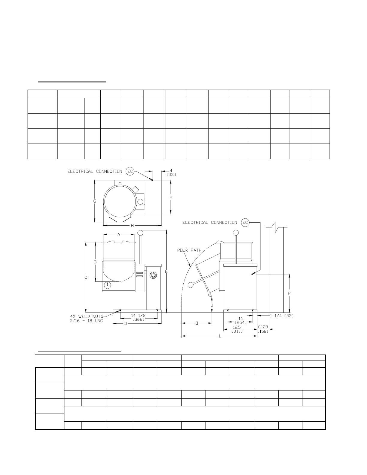
Service Connections
MODEL
CAPACITY
A B C D E G H J L P O
FT-4CE
4-Gal.
In
12
10.5
21.125
15.25
33.5
14.75
22
6.375
27.75
12.5
10
15 liters
mm
305
267
537
387
851
374
559
162
705
317
254
FT-6CE
6-Gal.
In
12
14.5
24.5
15.25
33.5
14.75
22
6.375
27.75
12.5
10
23 liters
mm
305
368
692
387
851
374
559
162
705
317
254
FT-10CE
10-Gal.
In
15.75
15
25.75
17.25
33
14.88
26
6.125
28
15
12.75
38 liters
mm
400
381
654
483
838
377
660
156
711
381
324
FT-12CE
12-Gal.
In
16
17
28
18
36.875
14.375
26
5.57
28
15
12.75
45 liters
mm
406
432
711
458
937
365
660
146
711
381
324
MODEL
pH
208 VAC
240 VAC
408 VAC
220/380 VAC
240/415 VAC
kW
AMP
kW
AMP
kW
AMP
kW
AMP
kW
AMP
FT-4CE
1
7.5
36
7.5
31.2
--
--
--
--
--
--
OR
FT-6CE
3
7.5
20.8
7.5
18
7.5 9 7.5
11.4
7.5
10.4
FT-10CE
1
12
57.7
12
50
12
14.4
12
18.2
12
16.7
OR
FT-12CE
3
12
33.3
12
28.8
12
14.5
12
31.5
12
28.9
INSTALLATION
Electrical Characteristics
3
Page 6
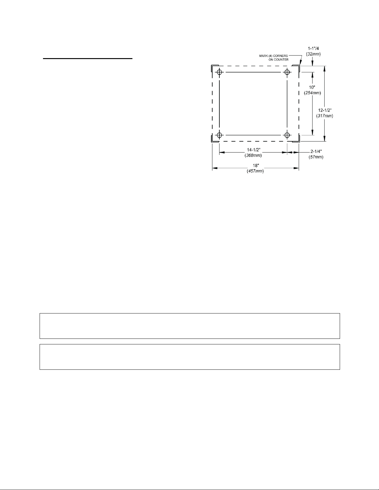
Installation Instructions:
WARNING:
Electrical and grounding connections must comply with the applicable portions of the National
Electrical Code and/or other local electrical codes
WARNING:
Disconnect electrical power supply and place a tag at the disconnect switch to indicate you are on the
circuit.
Figure 1
1. Immediately after unpacking, check for possible
shipping damage. If the kettle is found to be
damaged, save the packaging materials and
contact the carrier within 15 days of delivery.
2. The kettle must be installed in accordance with:
a. State and/or local codes.
b. In the USA, the National Electrical Code,
ANSI/NFPA-70 (latest edition). In Canada,
the Canadian Electrical Code, Part 1, CSA
Standard C22.1 (latest edition).
3. Position appliance on counter allowing sufficient
rear clearance from wall to tilt freely and
completely without obstruction.
4. Mark four corner locations of appliance base.
5. Remove appliance from counter and locate position of 4 holes as per Figure 1. Drill four 7/16"
diameter holes.
6. Apply a continuous bead of Silastic or other equivalent sealant along the complete perimeter edge
of the appliance base.
7. Use 5/16-18 Hex Cap Screws with suitable flat washers to bolt down. Screw length must be 1-1/4
long plus counter top thickness.
8. Wipe off excess sealant.
9. A Control Box with power supply equivalent to Electrical Rating of appliance should be located
conveniently nearby.
10. A waterproof electrical connection from power supply to console housing must be provided.
11. Ground appliance to terminal provided inside console housing.
12. Turn power ON and check for proper operation.
4
Page 7
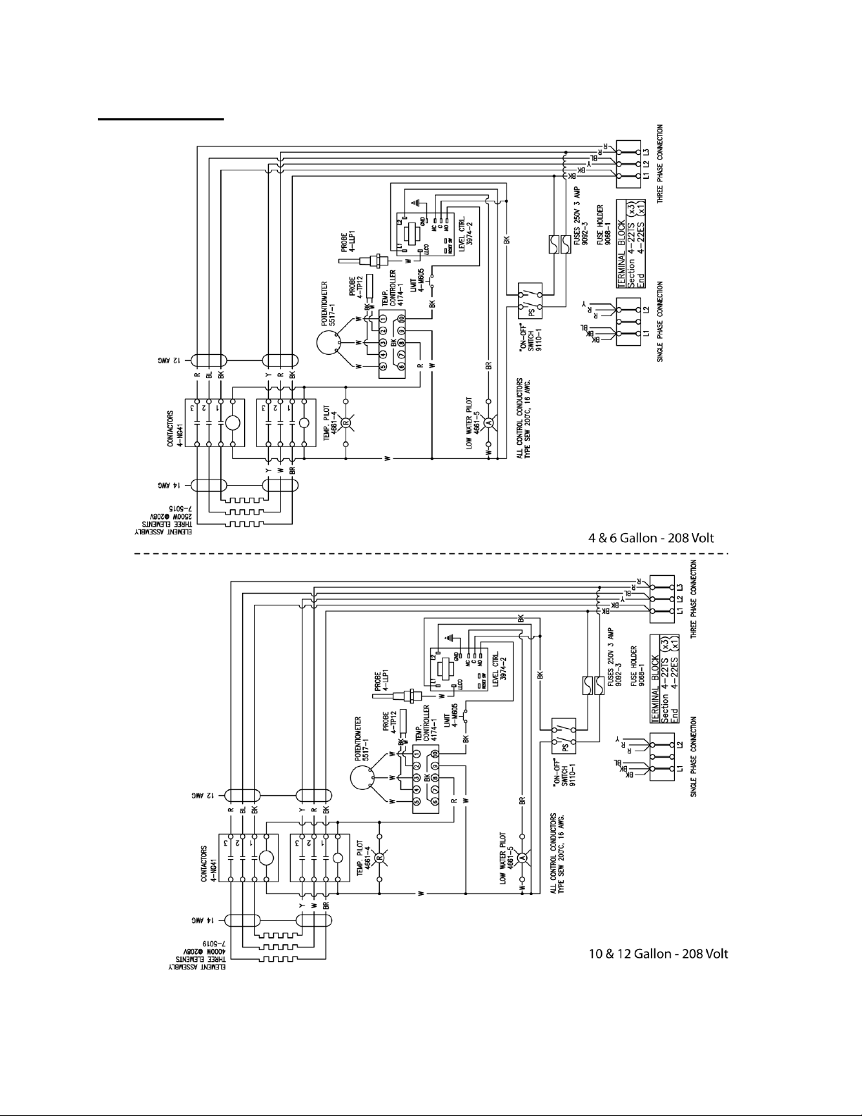
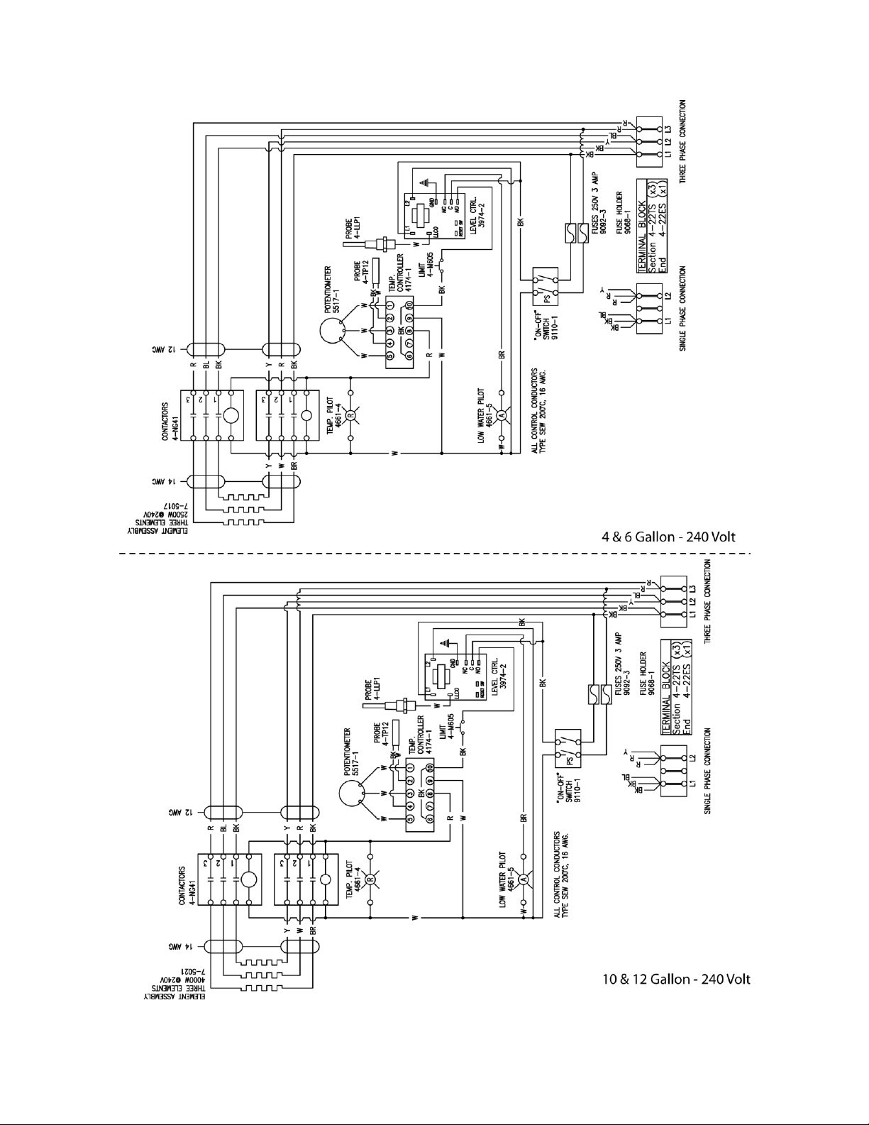
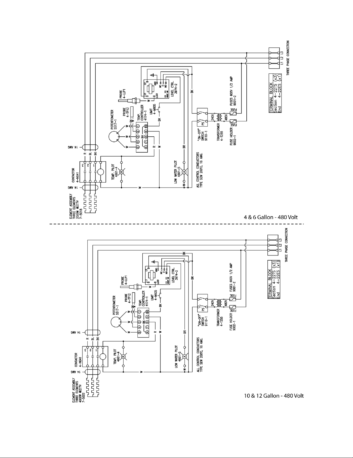
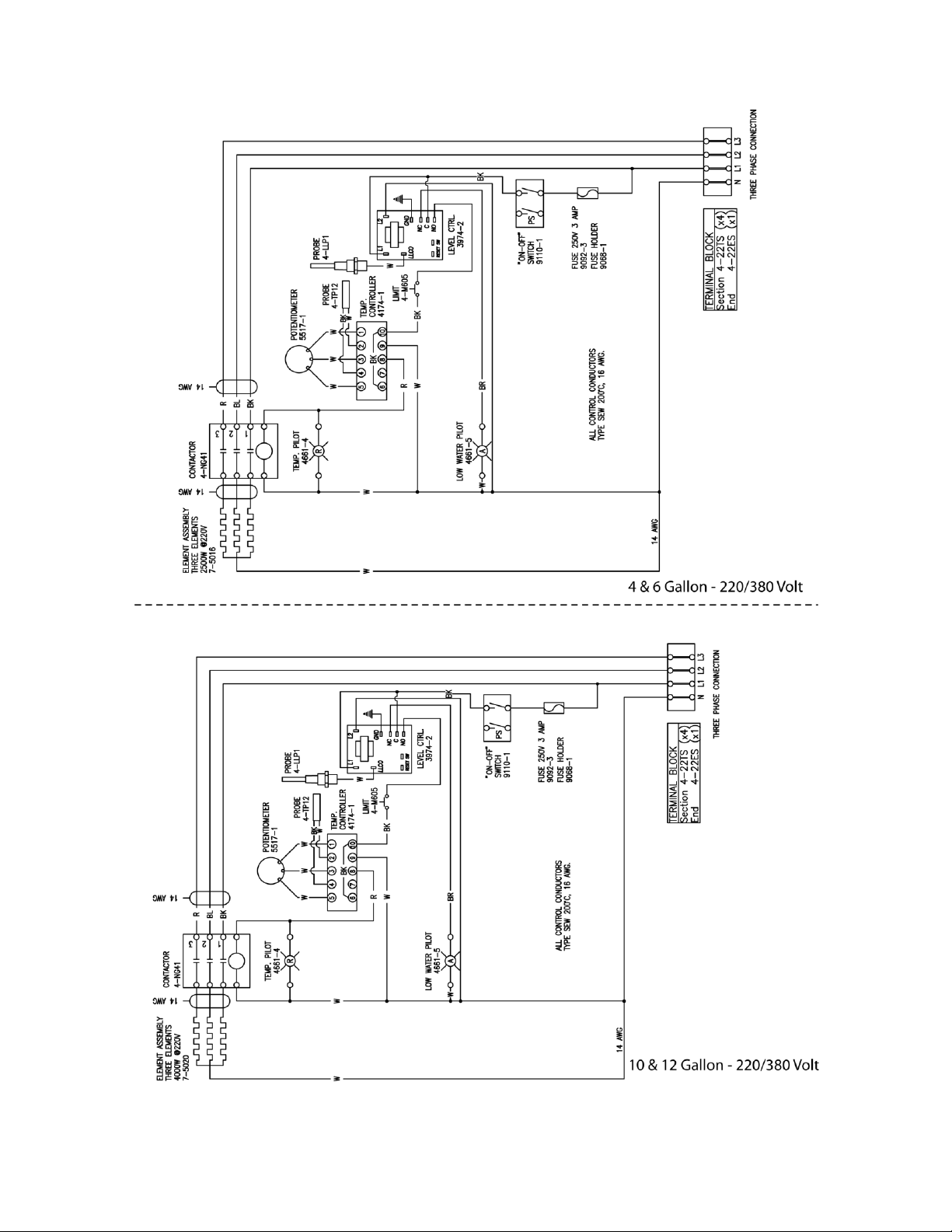
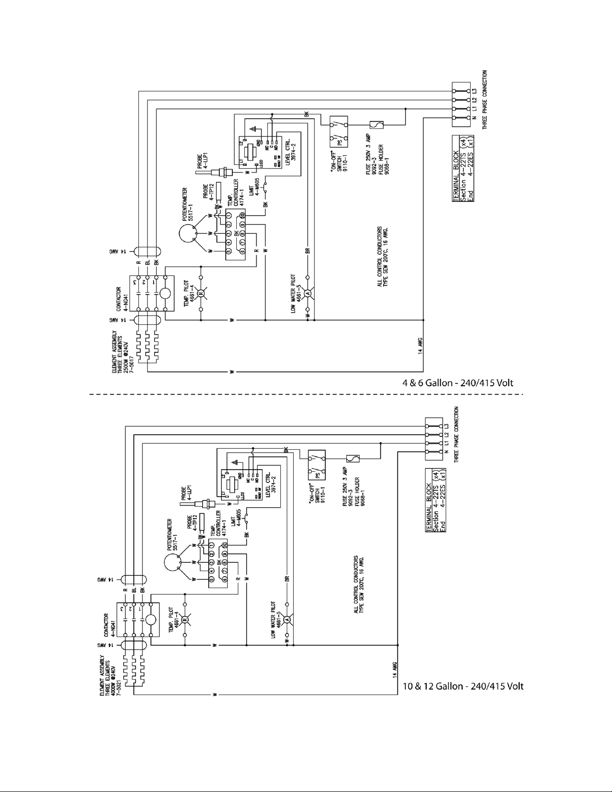
Wiring Diagrams
5
Page 8
6
Page 9
7
Page 10
8
Page 11
9
Page 12

OPERATION INSTRUCTIONS
ITEM NO.
DESCRIPTION
1
Tilt Handle
2
Power Switch
3
Low Water Indicator Light
4
Temperature (Heat Indicator) Light
5
Temperature Control Thermostat
6
Vacuum / Pressure Gauge
Figure 2
1. Ensure that the external electrical shut-off to the kettle is on.
2. Check pressure gauge for correct cold kettle reading. Reading should be in the green vacuum
zone. If reading is not in the vacuum zone, follow VENTING INSTRUCTION prior to using the
kettle.
3. Place power switch in ON position.
4. Preheat the kettle by placing thermostat knob at maximum and wait until TEMPERATURE light
goes off.
NOTE:
Preheating should not be used when cooking milk and egg food products which adhere to hot
cooking surfaces. These foods should be placed into kettle before heating is begun.
5. Add food to be cooked into the kettle.
6. Place thermostat knob at required temperature
setting with a temperature range from roughly
165°F to 289°F (74° C to 143° C, jacket
temperature.) Refer to chart on page 7.
7. When cooking is finished set thermostat
knob and power switch to the OFF position.
8. Pour finished product from kettle using tilt
handle. Be careful to avoid splashing.
9. Add water to kettle for cleaning purposes.
10. Wash kettle thoroughly. See CLEANING
procedure.
Kettle Controls (Figure 2)
10
Page 13

Thermostat Settings
Thermostat Settings
Approximate oF
Temperature (Water) oC
4
90
32 5 125
52 6 160
71 7 195
91 8 231
110 9 273
134
10
300
149
Tilting Instructions
Your kettle has the standard “Clean Lock” feature and may not be tilted without disengaging the tilt
knob located on the console at the top right. This feature locks the kettle in the upright position and
also allows the operator to lock the kettle at 105 degrees for ease of cleaning. To tilt the kettle the full
distance, the tilt lock knob must be disengaged from the cleaning position by pulling out the tilt lock
knob and tilting the kettle forward the full distance. Follow these steps to tilt kettle:
1. Pull out the tilt knob near top right of console.
2. Using kettle tilt handle pull kettle forward to desired angle of pour or until kettle locks at 105 degrees.
The tilt knob can be released after the kettle has been tilted approximately 10°.
3. Kettle will lock in position at 105 degrees and may be tilted further by pulling the tilt lock knob a
second time allowing the kettle to tilt the full distance.
4. To return the kettle to the upright position, pull out the tilt lock knob and tilt the kettle upward
until it locks in the upright position. The kettle should not move in either direction once in the
upright position.
11
Page 14

MAINTENANCE
NOTE:
Never scrape the inside of the kettle with metal tools, steel scouring pads, or abrasive cleaners.
Scratches will result which will spoil the kettle’s general appearance and make it harder to clean
and maintain a sanitary condition.
WARNING: Do not hose down appliance under any condition. Failure to comply will void warranty.
WARNING: It is NOT RECOMMENDED to use cleaning agents that are corrosive.
Cleaning Instructions
The kettle interior and exterior should be thoroughly washed after each use in preparation of a different
food.
1.
Add water and mild detergent to the kettle immediately after use.
2.
Scrub kettle interior with nylon brush.
3.
Loosen food which is stuck to kettle by allowing it to soak at a low temperature setting.
4.
Rinse with clear water and dry.
5.
Wipe down exterior, rinse and dry.
Use of cleaning agents that contain chloride, acids or salts are corrosive and may cause pitting and
corrosion when used over a period of time; this will reduce the life of the appliance.
Should pitting or corrosion occur this is not covered by warranty.
Follow the recommended cleaning instructions. Use a mild detergent, warm water and rinse thoroughly.
12
Page 15

1
Bleed Vent
2
Pressure Relief Valve
TROUBLESHOOTING
General
No general maintenance is required other than adhering to the Cleaning Procedure Instructions.
Low Water Level
Proper water level must be maintained within the jacket for the kettle to operate. Depletion of water
may occur from excessive opening of, or leakage through the safety relief valve.
If water is below required operating level, either initially at start-up or during use, the kettle will
automatically shut off, and the LOW WATER signal light will come on.
In order for the kettle to operate, the following procedure must be followed:
1. Trip the safety relief valve lever to relieve all pressure from the kettle jacket.
2. At exterior rear of kettle jacket remove nut from Air Vent.
3. Insert funnel into Air Vent opening and slowly add the indicated amount of distilled water for:
4. Rep l ac e A i r Ven t n u t.
(Filling Jacketed Reservoir)
FT-4CE & FT-6CE Add 50 oz. (1.5 liters)
FT-10CE & FT-12CE Add 100 oz. (3 liters)
5. Follow Air Venting Instructions below.
6. Continue normal Operating Procedure of kettle.
Venting Instructions
Check pressure gauge when kettle is cold. Gauge should be in the
green vacuum zone. If not, air is present which must be vented
(removed) for proper heating. Use the following procedures to vent air.
1. With an empty kettle, place power switch to the ON position.
2. Set temperature control thermostat to maximum. Heat kettle until heat indicator light goes off.
3. Using a 7/16" wrench, open bleed vent one full turn for 10 seconds and then close.
13
Page 16

4. Cool kettle. Check for proper vacuum in the green vacuum zone. If reading is not low enough,
CAUTION:
Before adding water to the reservoir, water supply should be analyzed to ensure that hardness is
no greater than 2.0- grains per gallon and pH level is within the range of 7.0-8.5. Water which fails
to meet these standards should be treated, or ionized distilled water with sodium used.
EQUIPMENT FAILURE CAUSED BY INADEQUATE WATER QUALITY IS NOT COVERED UNDER
WARRANTY.
repeat entire procedure, steps 1 to 3.
14
Page 17
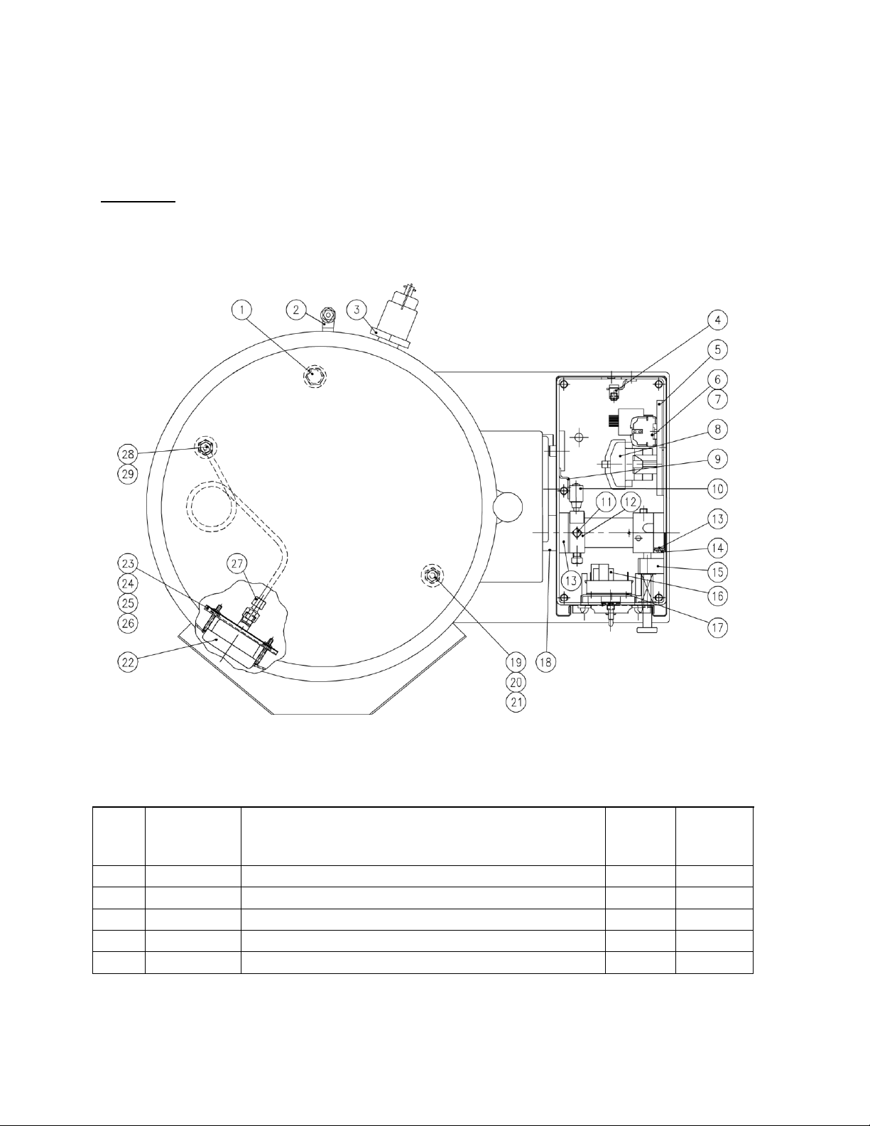
ILLUSTRATED PARTS LIST
Top View Parts List
ITEM
PART NO
DESCRIPTION
FT-4CE
FT-6CE
QTY.
FT-10CE
FT-12CE
QTY.
1
97-5425
Liquid Level Probe
1
1
2
97-5415
Air Vent Assembly
1
1
3
97-5009
Safety Relief Valve
1
1
4
97-5052
Ground Lug
1
1
5
98-6131
Component Mounting Bracket
1
1
Top View
15
Page 18

ITEM
PART NO
DESCRIPTION
FT-4CE
FT-6CE
QTY.
FT-10CE
FT-12CE
QTY.
6
10-6963
Terminal Block
3
3
10-6963
Terminal Block, (220/380, 240/415)
4
4
7
10-6962
Terminal Block, End Section
1
1
**8
97-5609
Contactor (208, 240V)
2
2
97-5609
Contactor (380, 416, 480, 600V)
1
1
9
97-7111
Micro Switch Bracket
1
1
10
97-5414
Micro Switch
1
1
11
97-7112
Square Head Set Screw, 3/8-16 NC x 1/2
2
2
12
97-6518
Actuating Collar
1
1
13
97-5340
Trunnion Bronze Bearing
1
1
14
97-5650
Trunnion Bearing Housing
2
2
15
97-7113
Marine Lock Assembly
1
1
16
97-5797
Temperature Controller
1
1
17
97-6515
Mounting Plate
1
1
18
97-6973
Boston Bronze Bearing
1
1
19
97-6500
Reducer, 3/8 NPT - 1/4 NPT
1
1
20
97-6398
Compression Fitting
1
1
21
97-7114
Temperature Probe
1
1
22
97-6563
Pressure Gauge
1
1
*
97-5620
“O” Ring
1
1
23
97-6499
Pressure Gauge Plate
1
1
24
97-7115
Hex Nut #10 - 32 NC Zinc
2
2
25
97-7116
Flat Washer #10 Zinc
2
2
26
97-7117
Split Lock Washer #10 Zinc
2
2
27
97-5046
Compression Fitting
1
1
28
97-5000
Compression Fitting
1
1
29
97-5146
Copper Tubing
1
97-5145
Copper Tubing
1
*30
97-5648
Wire Harness - Thermostat
1
1
*31
97-5649
Wire Harness - Elements
1
1
*32
97-7118
Hex Bolt, 5/16-18 x 1-1/4
4
4
*33
97-7119
Flat Washer, 5/16 x 1-1/2 OD
4
4
*34
97-6368
Relief Valve Extension
1
1
* NOT SHOWN.
** SELECT AS REQUIRED.
16
Page 19

Front View
17
Page 20

Front View Parts List
ITEM
PART NO
DESCRIPTION
FT-4CE
FT-6CE
QTY.
FT-10CE
FT-12CE
QTY.
1
97-5008
Handle Knob
1
1
2
97-5115
Tilt Handle
1
1
3
97-5116
Acorn Nut, 3/8" - 16 UNC
1
1
4
97-7120
Element Access Cover Assembly
1
1
5
97-6529
Gasket
1
1
6
97-7121
Internal Tooth Lock Washer, 1/4"
1
1
7
97-7122
Hex. Nut, 1/4" - 20 NC Zinc
1
1
*
97-6530
Yoke, Access Cover
1
1
8
97-6965
Console Cover Gasket
1
1
9
97-7123
Top Cover, Console
1
1
10
97-6981
Decal
1
97-7124
Decal
1
11
97-5617
Potentiometer Complete w/ Wires &Push On Terminals
1
1
12
97-5013
Knob
1
1
13
98-6162
Temperature Pilot, Red
1
1
14
97-6513
Power Switch
1
1
15
97-6512
Low Water Pilot, Amber
1
1
16
97-7125
Liquid Level Control
1
1
17
97-7126
Hex Nut, 3/8 - 16 NC Zinc
5
5
18
97-7127
Flat Washer, 3/8" Zinc
5
5
19
97-6506
Trunnion Box Bottom
1
97-6507
Trunnion Box Bottom
1
97-7128
Gasket
1
97-6922
Gasket
2
2
97-6739
Screw, 10-32 x 1/2
1
**20
97-5015
Element Assembly, 7.5 kW, 208V
1
97-5016
Element Assembly, 7.5 kW, 220/380V
1
97-5017
Element Assembly, 7.5 kW, 240/416V
1
97-5018
Element Assembly, 7.5 kW, 480V
1
97-7129
Element Assembly, 7.5 kW, 600V
1
97-5019
Element Assembly, 12 kW, 208V
1
97-5020
Element Assembly, 12 kW, 220/380V
1
97-5021
Element Assembly, 12 kW, 240/416V
1
97-5022
Element Assembly, 12 kW, 480V
1
97-7130
Element Assembly, 12 kW, 600V
1
21
97-7131
Element Gasket
1
97-5025
Element Gasket
4
4
22
97-7132
Hex. Screw 5/16-18 NC x 3/4, ST/ST
1
1
23
97-7133
Base Assembly
1
18
Page 21

ITEM
PART NO
DESCRIPTION
FT-4CE
FT-6CE
QTY.
FT-10CE
FT-12CE
QTY.
24
97-6504
Bottom Cover
1
97-6505
Bottom Cover
1
25
97-6502
Bottom Cover Gasket
1
97-6503
Bottom Cover Gasket
1
26
97-7134
Hex. Screw, 5/16 - 18 NC x 1/2 Zinc
1
1
*27
97-7135
Element Terminal Screw, 10 - 32 x 3/8
4
4
*28
97-7136
Faucet Bracket, (Optional)
1
1
*29
97-7137
Kettle Cover, (Optional)
1
97-7138
Kettle Cover, (Optional)
1
* **30
97-5616
Transformer, 380/416V-120V, 50/60 Hz, 100VA
1
1
97-5613
Transformer, 480V-120V, 60 Hz, 100VA
1
1
98-6191
Transformer, 600V-120V, 60 Hz, 100VA
1
1
* **31
97-5476
Fuse, 250V, 3A, (208 - 240V Units)
2
2
97-5476
Fuse, 250V, 3A, (200/380V and 240/415V Units)
1
1
98-6188
Fuse, 1/2 A, 600V, (380 - 600V Units)
2
2
* **32
97-5864
Fuse Holder, (208 - 240V Units)
2
2
97-5864
Fuse Holder, (220/380V and 240/415V Units)
1
1
98-6187
Fuse Holder, (380 - 600V Units)
1
1
* NOT SHOWN.
** SELECT AS REQUIRED.
19
Page 22
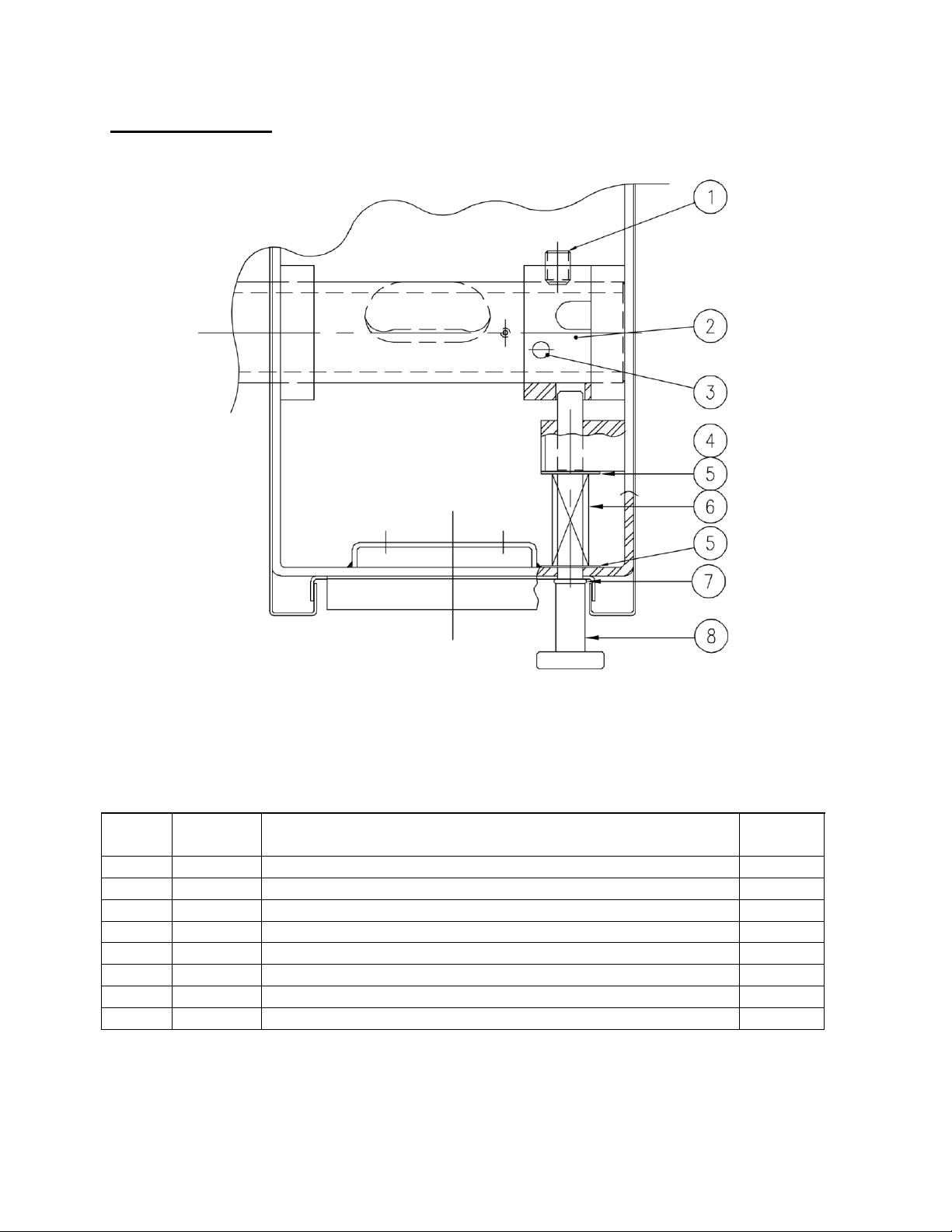
Tilting Mechanism
Tilting Mechanism Parts List
ITEM
MF PART
NO
DESCRIPTION
QTY.
1
97-7139
Hex. Socket Set Screw, 3/8 -16 NC x 1/2
1
2
97-7140
Cam Collar
1
3
97-7141
Spring Pin, 1/4 Diameter x 2 1/4" Long
1
4
97-6677
External Ring Spae-Naur #R1000-37
1
5
97-7142
Plain Washer, 3/8 ID x 7/8 OD x T = 0.048
2
6
97-5917
Spring
1
7
97-6679
“O” Ring Seal, E-515-80-11, 5/16 I.D.
1
8
97-6680
Locking Pin
1
20
Page 23

MATERIAL SAFETY DATA SHEET
Propylene Glycol
CAS # 000057-55-6
94%
Dipotassium Phosphate
CAS # 007758-11-4
<5%
Deionized Water
CAS # 007732-18-5
<5%
PREPARATION INFORMATION:
Prepared for use in Canada by: E H & S Product Regulatory Management Department DOW
CHEMICAL CANADA INC.
P.O. Box 1012
Sarnia, Ontario, N7T 7K7
(800) 331-6451
CHEMICAL PRODUCT AND COMPANY IDENTIFICATION
IN CASE OF EMERGENCY:
Product: DOWFROSTTM HD HEAT TRANSFER FLUID, DYED
Product Code: 04632
Effective Date: 2/20/01 Date Printed: 07/10/02 MSD: 002239
DOW CHEMICAL CANADA INC. P.O.
Box 1012
Sarnia, Ontario
Canada, N7T 7K7
24-Hour Emergency Phone Number (USA): (989) 636-4400
Product: DOWFROSTTM HD HEAT TRANSFER FLUID, DYED
Product Code: 04632
Effective Date: 08/03/04 Date Printed: 08/04/04 MSD: 002239
Fort Saskatchewan, Alberta: (780) 998-8282
Sarnia, Ontario: (519) 339-3711
Varennes, Quebec: (450) 652-1000
The DOW CHEMICAL COMPANY, Midland, MI, USA, 48674 Customer
Information Center: 800-258-2436
COMPOSITION/INFORMATION ON INGREDIENTS
TM indicates a trademark of The Dow Chemical Company.
21
Page 24

Product: DOWFROSTTM HD HEAT TRANSFER FLUID, DYED
Product Code: 04632
Effective Date: 08/03/04, Date Printed: 08/04/04, MSD: 002239
HAZARDS IDENTIFICATION
EMERGENCY OVERVIEW
Clear yellow liquid. Odourless. Avoid temperatures above 450°F, 232°C.
POTENTIAL HEALTH EFFECTS
EYE:
May cause slight transient (temporary) eye irritation. Corneal injury is unlikely. Mists may cause
(See Section 11 for toxicological data.)
eye irritation.
SKIN CONTACT:
Prolonged contact is essentially nonirritating to skin. A single prolonged exposure is not
likely to result in the material being absorbed through skin in harmful amounts. Repeated exposures may
cause flaking and softening of skin.
INGESTION:
Single dose oral toxicity is considered to be extremely low. No hazards anticipated
from swallowing small amounts incidental to normal handling operations.
INHALATION:
At room temperature, vapours are minimal due to physical properties. Mists may
cause irritation of upper respiratory tract (nose and throat).
SYSTEMIC (OTHER TARGET ORGAN) EFFECTS:
Repeated excessive exposure to propylene glycol
may cause central nervous system effects.
CANCER INFORMATION:
TERATOLOGY (BIRTH DEFECTS):
Did not cause cancer in laboratory animals.
Birth defects are unlikely. Exposures having no adverse effects on the
mother should have no effect on the fetus.
REPRODUCTIVE EFFECTS:
In animal studies, has been shown not to interfere with reproduction.
TM indicates a trademark of The Dow Chemical Company.
22
Page 25

Product:
Effective Date: 08/03/04, Date Printed: 08/04/04, MSD: 002239
FIRST AID
EYES: Flush eyes with plenty of water.
SKIN: Wash off in flowing water or shower.
INGESTION: No adverse effects anticipated by this route of exposure incidental
INHALATION: Remove to fresh air if effects occur. Consult a physician.
NOTE TO PHYSICIAN: No specific antidote. Supportive care. Treatment based on
DOWFROSTTM HD HEAT TRANSFER FLUID, DYED
Product Code: 04632
to proper industrial handling.
judgment of the physician in response to reactions of the patient.
FIRE FIGHTING MEASURES
FLAMMABLE PROPERTIES
FLASH POINT: 214°F, 107°C (based on a similar material)
METHOD USED: PMCC
AUTOIGNITION TEMPERATURE: Not determined.
FLAMMABILITY LIMITS
LFL: Not determined.
UFL: Not determined
TM indicates a trademark of The Dow Chemical Company.
23
Page 26

Product: DOWFROSTTM HD HEAT TRANSFER FLUID, DYED
Product Code: 04632
Effective Date: 08/03/04, Date Printed: 08/04/04, MSD: 002239
HAZARDOUS COMBUSTION PRODUCTS
addition to unidentified toxic and/or irritating compounds. Hazardous combustion products may
include and are not limited to carbon monoxide and carbon dioxide.
OTHER FLAMMABILITY INFORMATION
application of direct water stream to hot liquids. Flammable concentrations of vapour can accumulate at
temperatures above 214°F. Liquid mist of this product can burn. Spills of these organic liquids on hot
fibrous insulations may lead to lowering of the autoignition temperatures possibly resulting in
spontaneous combustion. Container may rupture from gas generation in a fire situation.
EXTINGUISHING MEDIA
resistant foams (ATC type) are preferred if available. General purpose synthetic foams (including AFFF) or
protein foams may function, but much less effectively. Do not use direct water stream. May spread fire.
MEDIA TO BE AVOIDED
FIRE FIGHTING INSTRUCTIONS
liquids may be moved by flushing with water to protect personnel and minimize property damage.
Burning liquids may be extinguished by dilution with water. Do not use direct water stream. May spread
fire. Fight fire from protected location or safe distance. Consider use of unmanned hose holder or
monitor nozzles. Use water spray to cool fire exposed containers and fire affected zone until fire is
out and danger of re-ignition has passed. Immediately withdraw all personnel from area in case of
rising sound from venting safety device or discolouration of the container. Move container from fire
area if this is possible without hazard.
: Water fog or fine spray, carbon dioxide, dry chemical, foam. Alcohol
: Do not use direct water stream.
: Keep people away. Isolate fire area and deny unnecessary entry. Burning
: During a fire, smoke may contain the original material in
: Violent steam generation or eruption may occur upon
PROTECTIVE EQUIPMENT FOR FIRE FIGHTERS
apparatus (SCBA) and protective fire fighting clothing (includes fire fighting helmet, coat, pants, boots
and gloves). If protective equipment is not available or not used, fight fire from a protected location
or safe distance.
TM indicates a trademark of The Dow Chemical Company.
: Wear positive-pressure self-contained breathing
24
Page 27

Product:
Effective Date: 08/03/04, Date Printed: 08/04/04, MSD: 002239
DOWFROSTTM HD HEAT TRANSFER FLUID, DYED
Product Code: 04632
ACCIDENTAL RELEASE MEASURES (See Section 15 for Regulatory Information)
PROTECT PEOPLE: Use appropriate safety equipment. For additional information, refer to Section 8,
Exposure Controls/ Personal Protection.
PROTECT THE ENVIRONMENT: Avoid contamination of all waterways. CLEAN-UP:
See Section 13, Disposal Consideration.
HANDLING AND STORAGE
SPECIAL PRECAUTIONS TO BE TAKEN IN HANDLING AND STORAGE: No special handling
requirements data available.
HANDLING: See Section 8, Exposure Controls/Personal Protection. STORAGE:
See Section 10, Stability and Reactivity.
EXPOSURE CONTROLS/PERSONAL PROTECTION
ENGINEERING CONTROLS: Provide general and/or local exhaust ventilation to control airborne
levels below the exposure guidelines.
PERSONAL PROTECTIVE EQUIPMENT
EYE/FACE PROTECTION: Use safety glasses. Safety glasses should be sufficient for most operations;
however, for misty operations wear chemical goggles.
SKIN PROTECTION: Use gloves impervious to this material.
RESPIRATORY PROTECTION: Atmospheric levels should be maintained below the exposure guideline. When
respiratory protection is required for certain operations, use an approved air-purifying respirator. In misty
atmospheres, use an approved mist respirator.
TM indicates a trademark of The Dow Chemical Company.
25
Page 28

Product:
Effective Date: 08/03/04, Date Printed: 08/04/04, MSD: 002239
EXPOSURE GUIDELINES: Propylene glycol: AIHA WEEL is 10 mg/m3 for total vapour and aerosol.
PHYSICAL AND CHEMICAL PROPERTIES
APPEARANCE/PHYSICAL STATE: Clear yellow liquid.
ODOUR: Odourless
VAPOUR PRESSURE: 0.22 mmHg @ 20°C
VAPOUR DENSITY: 2.6
BOILING POINT: 320°F, 160°C
SOLUBILITY IN WATER/MISCIBILITY: Complete
SPECIFIC GRAVITY OR DENSITY: 1.058 @ 25/25°C
DOWFROSTTM HD HEAT TRANSFER FLUID, DYED
Product Code: 04632
STABILITY AND REACTIVITY
typical use temperatures.
CONDITIONS TO AVOID: Avoid use temperatures above 450°F, 232°C. Product can degrade at elevated
temperatures. Generation of gas during decomposition can cause pressure in closed systems.
INCOMPATIBILITY WITH OTHER MATERIALS: Avoid contact with oxidizing materials. Avoid contact with
strong acids
HAZARDOUS DECOMPOSITION PRODUCTS: Hazardous decomposition products depend upon
temperature, air supply and the presence of other materials.
HAZARDOUS POLYMERIZATION: Will not occur.
TOXICOLOGICAL INFORMATION
toxicological data, write or call the address or non-emergency number shown in Section 1).
SKIN: The LD50 for skin absorption in rabbits is >10,000 mg/kg.
CHEMICAL STABILITY: Thermally stable at
(See Section 3 for Potential Health Effects. For detailed
TM indicates a trademark of The Dow Chemical Company.
26
Page 29

Product:
Effective Date: 08/03/04, Date Printed: 08/04/04, MSD: 002239
INGESTION: The oral LD50 for rats is 20,000 - 34,000 mg/kg.
MUTAGENICITY: In vitro mutagenicity studies were negative. Animal mutagenicity studies were
negative.
DOWFROSTTM HD HEAT TRANSFER FLUID, DYED
Product Code: 04632
ECOLOGICAL INFORMATION
number shown in Section 1.)
ENVIRONMENTAL FATE
MOVEMENT & PARTITIONING: Based largely or completely on data for major component(s).
Bioconcentration potential is low (BCF less than 100 or Log Pow less than 3). Potential for mobility in
soil is very high (Koc between 0 and 50).
DEGRADATION AND PERSISTENCE: Based largely or completely on data for major component(s).
Material is readily biodegradable. Passes OECD test(s) for ready biodegradability. Degradation is
expected in the atmospheric environment within minutes to hours.
ECOTOXICITY: Based largely or completely on data for major component(s). Material is practically
non-toxic to aquatic organisms on an acute basis (LC50/EC50 >100 mg/L in most sensitive species).
DISPOSAL CONSIDERATIONS
DISPOSAL: DO NOT DUMP INTO ANY SEWERS, ON THE GROUND OR INTO ANY BODY OF WATER. All
disposal methods must be in compliance with all Federal, State/Provincial and local laws and
regulations. Regulations may vary in different locations. Waste
(For detailed Ecological data, write or call the address or non-emergency
(See Section 15 for Regulatory Information)
characterizations and compliance with applicable laws are the responsibility solely of the waste generator.
THE DOW CHEMICAL COMPANY HAS NO CONTROL OVER THE MANAGEMENT PRACTICES OR
MANUFACTURING PROCESSES OF PARTIES HANDLING OR USING THIS MATERIAL. THE INFORMATION
PRESENTED HERE PERTAINS ONLY TO THE PRODUCT AS SHIPPED IN ITS INTENDED CONDITION AS
DESCRIBED IN MSDS SECTION 2 (Composition/Information On Ingredients).
TM indicates a trademark of The Dow Chemical Company.
27
Page 30

Product:
Effective Date: 08/03/04, Date Printed: 08/04/04, MSD: 002239
FOR UNUSED & UNCONTAMINATED PRODUCT, the preferred options include sending to a licensed,
permitted: recycler, reclaimer, incinerator or other thermal destruction device.
As a service to its customers, Dow can provide names of information resources to help identify waste
management companies and other facilities which recycle, reprocess or manage chemicals or
plastics, and that manage used drums. Telephone Dow’s Customer Information Center at 800-258-2436
or 989-832-1556 for further details.
TRANSPORT INFORMATION
DOWFROSTTM HD HEAT TRANSFER FLUID, DYED
Product Code: 04632
DEPARTMENT OF TRANSPORTATION (D.O.T.)
transportation regulations, product shipping papers, or contact your Dow representative.
CANADIAN TDG INFORMATION: For TDG regulatory information, if required, consult
transportation regulations, product shipping papers, or your Dow representative.
REGULATORY INFORMATION
NOTICE: The information herein is presented in good faith and believed to be accurate as of the
effective date shown above. However, no warranty, express or implied is given. Regulatory requirements are
subject to change and may differ from one location to another; it is the buyer’s responsibility to ensure that
its activities comply with federal, state or provincial, and local laws. The following specific information is
made for the purpose of complying with numerous federal, state or provincial, and local laws and
regulations. See other sections for health and safety information.
(Not meant to be all-inclusive – selected regulations represented).
: For D.O.T. regulatory information, if required, consult
TM indicates a trademark of The Dow Chemical Company.
28
Page 31

Product:
Effective Date: 08/03/04, Date Printed: 08/04/04, MSD: 002239
U.S. REGULATIONS
SARA 313 INFORMATION: To the best of our knowledge, this product contains no chemical subject to
SARA Title III Section 313 supplier notification requirements.
SARA HAZARD CATEGORY: This product has been reviewed according to the EPA “Hazard Categories”
promulgated under Sections 311 and 312 of the Superfund Amendment and Reauthorization Act of
1986 (SARA Title III) and is considered, under applicable definitions, to meet the following categories:
Not to have met any hazard category.
TOXIC SUBSTANCES CONTROL ACT (TSCA):
All ingredients are on the TSCA inventory or are not required to be listed on the TSCA inventory.
STATE RIGHT-TO-KNOW: The following product components are cited on certain state lists as
mentioned. Non-listed components may be shown in the composition section of the MSDS.
DOWFROSTTM HD HEAT TRANSFER FLUID, DYED
Product Code: 04632
CHEMICAL NAME CAS NUMBER LIST
1, 2-Propanediol 000057-55-6 PA1
PA1= Pennsylvania Hazardous Substance (present at greater than or equal to 1.0%). OSHA
HAZARD COMMUNICATION STANDARD:
This product is not a “Hazardous Chemical” as defined by the OSHA Hazard Communication Standard, 29
CFR 1910.1200.
TM indicates a trademark of The Dow Chemical Company.
29
Page 32

Product:
Effective Date: 08/03/04, Date Printed: 08/04/04, MSD: 002239
CANADIAN REGULATIONS
WHMIS INFORMATION: The Canadian Workplace Hazardous Materials Information System (WHMIS)
Classification for this product is:
This product is not a “Controlled Product” under WHMIS.
CANADIAN ENVIRONMENTAL PROTECTION ACT (CEPA)
This product contains one or more substances which are not listed on the Canadian Domestic
Substances List (DSL). Contact your Dow representative for more information.
OTHER INFORMATION
MSDS STATUS: Revised Section 8 (Exposure Guidelines).
DOWFROSTTM HD HEAT TRANSFER FLUID, DYED
Product Code: 04632
TM indicates a trademark of The Dow Chemical Company.
The information herein is given in good faith, but no warranty, express or implied, is made.
Consult The Dow Chemical Company for further information.
29
 Loading...