

Page 1
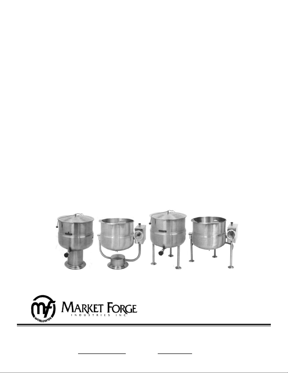
OWNER’S MANUAL
DIRECT STEAM KETTLES
PEDESTAL & TRI-LEG
PEDESTAL MODELS:
F-20P (Stationary)
F-30P (Stationary)
F-40P (Stationary)
F-60P (Stationary)
F-80P (Stationary)
F-100P (Stationary)
FT-20P (Tilting)
FT-30P (Tilting)
FT-40P (Tilting)
FT-60P (Tilting)
FT-80P (Tilting)
FT-100P (Tilting)
TRI-LEG MODELS:
F-20L (Stationary)
F-30L (Stationary)
F-40L (Stationary)
F-60L (Stationary)
F-80L (Stationary)
F-100L (Stationary)
FT-20L (Tilting)
FT-30L (Tilting)
FT-40L (Tilting)
FT-60L (Tilting)
FT-80L (Tilting)
FT-100L (Tilting)
An Employee Owned Company
35 Garvey Street, Everett, MA, 02149 Form No. S-1060 Rev. A 08/11
Tel: (617) 387-4100, Fax: (617) 387-4456 (MA)
Toll Free: (866) 698-3188, Outside MA Fax: (800) 227-2659
Customer Service: custserv@mi.com, Visit Us At: www.mi.com
Page 2

TABLE OF CONTENTS
INTRODUCTION ............................................................... 1
INSTALLATION INSTRUCTIONS
Receiving ........................................................................... 1
Installation ......................................................................... 1
Installation Check .............................................................. 1
OPERATING INSTRUCTIONS
Operating Instructions ....................................................... 2
Controls ............................................................................ 2
GENERAL INFORMATION
Stationary Pedestal ........................................................... 3
Tilting Pedestal .................................................................. 3
Operation Requirements ................................................... 3
Steam Flow Requirements ................................................ 3
Details and Dimensions Stationary Pedestal..................... 4
Details and Dimensions Tilting Pedestal ........................... 5
Stationary Tri-Leg .............................................................. 6
Tilting Tri-Leg ..................................................................... 6
Operation Requirements ................................................... 6
Steam Flow Requirements ................................................ 6
Details and Dimensions Stationary Tri-Leg ....................... 7
Details and Dimensions Tilting Tri-Leg .............................. 8
MAINTENANCE
Cleaning ............................................................................ 9
Inspection Checks ............................................................. 9
ILLUSTRATED PARTS LIST
Operation ........................................................................... 10
Tilt Console ........................................................................ 11
Draw-Off Valve .................................................................. 13
i
Page 3

INTRODUCTION
The Market Forge Direct Connected Steam
Jacketed Kettle is a steam operated pressure
vessel designed for cooking. It consists of a
welded satin nish of stainless steel (type 304)
kettle with double wall construction, forming a
surrounding chamber around the kettle into
which steam is introduced as a source of heat
for cooking. Steam input plumbing is equipped
with a manual control valve.
Unit is mounted on stainless steel tubular tri-
legs. Each leg is tted with a four hole adjustable ange foot for securing the kettle to the
oor.
INSTALLATION INSTRUCTIONS
Unit is also equipped with a tangent draw-off
valve with heat resistant handle for the removal
of kettle contents and a condensate return assembly that permits removal of excessive condensate. A two piece, hinged lid covers the kettle opening.
Operation is by direct steam at a minimum of
5 PSI (0.4kg/cm2) and a maximum of 55 PSI
(3.9kg/cm2).
RECEIVING:
The kettle is shipped strapped and bolted to a skid
and covered by a carton which is nailed to the skid.
The packing materials must be carefully removed
prior to installation. Inspect each unit. If any damage has been incurred during shipment, report
same within two days to both the carrier and Market
Forge Ind., Inc.
INSTALLATION:
Select a location to provided drainage directly
1.
below the draw-off valve.
Mark hole location through ange adjustable
2.
feet.
On marked hole locations, drill holes and insert
3.
expansion shields to accommodate 5/16” size
lag bolts, 4 bolts per foot.
Level unit in proposed location by turning ad-
4.
justable ange feet.
Bolt down unit and seal with Silastic or other
5.
equivalent sealing compound.
NOTE: Sealant must be applied not only to bolt
heads, but also around ange feet making contact with the oor surface. This application fullls NSF Requirements.
Connect steam line to kettle. Ensure that line is
6.
clean and checked for foreign matter and that a
steam control valve strainer is fairly convenient
to kettle.
Connect kettle condensate return line to drain.
7.
WARNING: If incoming steam pressure is greater
than kettle maximum operating pressure, then a
pressure reducing valve MUST be installed in the
steam line.
A steam line pressure gauge is also recommended
to determine the actual amount of steam entering
the kettle.
NOTE: If large amounts of water accumulate in
steam line, install one or more ball oat traps in the
line to eliminate water.
INSTALLATION CHECK OUT:
Fill kettle part way with water.
1.
Turn steam supply valve on slowly.
2.
Pull safety valve lever. Observe that steam es-
3.
capes freely.
WARNING: Stay clear of exhaust from valve
outlet when checking safety valve.
Observe that water comes to a boil in the kettle.
4.
Allow approximately 2 to 5 minutes per gallon
of water.
Close steam supply valve.
5.
1
Page 4
OPERATING INSTRUCTIONS
Close draw-off valve.
1.
Place food to be cooked into kettle.
2.
Slowly turn steam control valve counter-
3.
clockwise (ON) to full open position.
Slowly open pressure relief valve (rear of
4.
kettle) to allow all air to escape.
WARNING: Stay clear of relief valve outlet
during step 4 to avoid scalding.
Adjust steam control valve depending on
5.
type of food prepared.
NOTE: If water or food does not boil in 3-4
minutes per gallon, check incoming pres-
sure to determine whether it is adequate to
operate the kettle efciently.
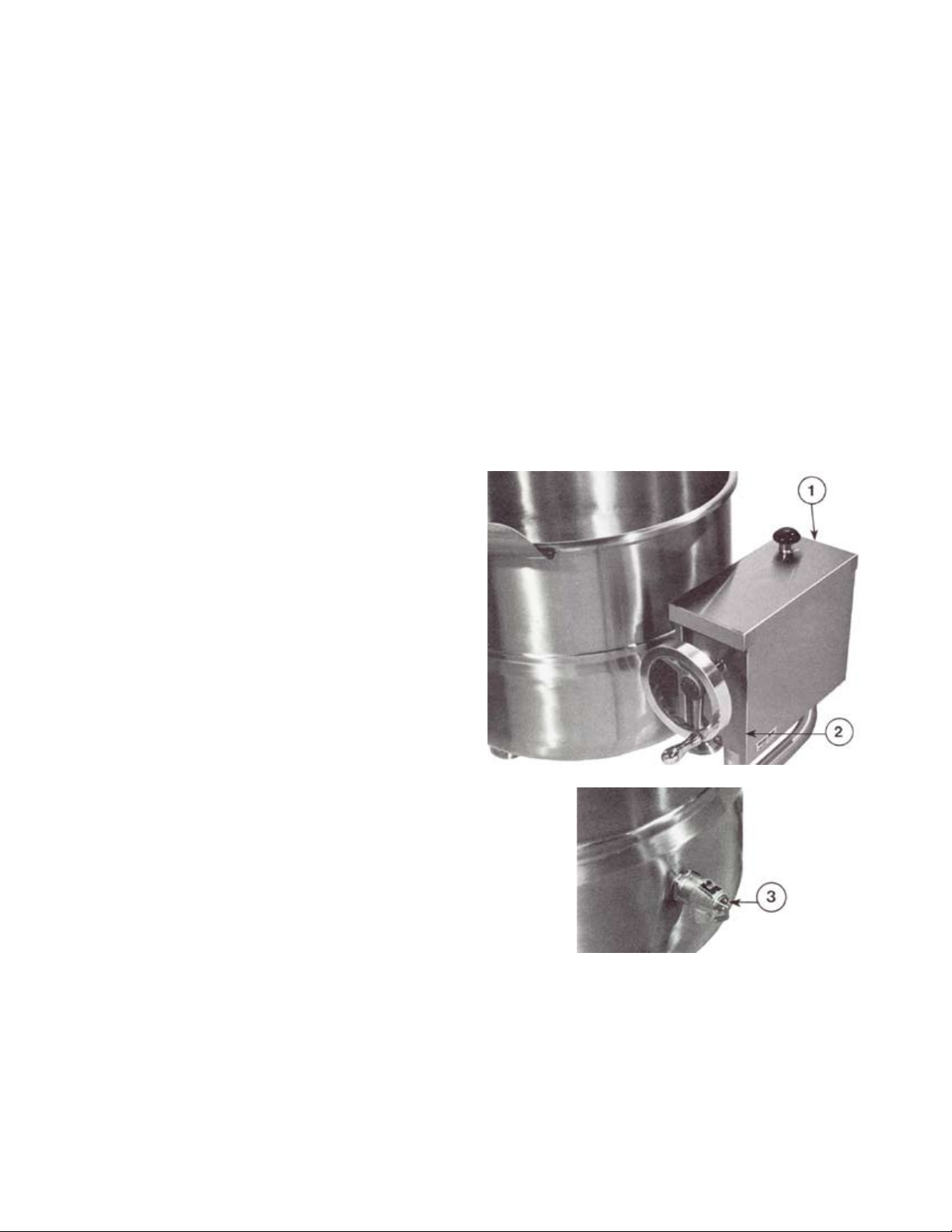
CONTROLS:
Steam Control Valve
1.
Tilt Wheel
2.
Pressure Relief Valve (rear of kettle)
3.
Draw-Off Valve (not shown)
4.
When cooking is nished, turn off steam
6.
by turning steam control valve clockwise.
Pour Finished product from kettle using ei-
7.
ther tilt wheel (wheel is equipped for tilting
models only ) or draw-off valve. Be careful
to avoid splashing.
Add water to kettle for cleaning purposes.
8.
Wash kettle thoroughly (see daily cleaning
9.
instructions).
2
Page 5
GENERAL INFORMATION
STATIONARY PEDESTAL:
F- 20P, F- 30P , F- 40P, F- 60P, F- 80P & F- 100P.
Kettle will be constructed of welded satin nish
stainless steel, type 304. A double wall kettle inte-
rior will form a steam jacket around the lower 2/3
of the kettle. The kettle bottom will be of elliptical
design for superior heat circulation.
Unit will be mounted on a stainless steel pedestal base. Pedestal base will have four holes evenly
spaced for securing unit to the oor.
Convenience features will include a hinged counter-balanced stainless steel cover and a 1 1/2”
(38mm) sanitary draw-off valve with strainer and
heat resistant handle.
Unit will include as standard a Steam Control Kit
(CKT-1).
OPERATION WILL BE BY:
Direct steam at 15–50 PSI (1.0–3.5 kg/cm2).
1/3 BHP required per kettle. Over 50 PSI (3.5 kg/
cm2), a pressure reducing valve is required.
TILTING PEDESTAL:
FT- 20P, FT- 30P , FT- 40P, FT- 60P & FT- 80P.
Kettle will be constructed of welded satin nish
stainless steel, type 304. A double wall kettle inte-
rior will form a steam jacket around the lower 2/3
of the kettle. The kettle bottom will be of elliptical
design for superior heat circulation.
Mounting frame of tubular stainless steel pipe will
be formed in a yoke xed to a cylindrical pedestal
base. Pedestal base will have four 7/16” (11mm)
holes evenly spaced for securing unit to oor.
Trunnion mounts will support the kettle to allow
tilting. Tilting mechanism with high position hand
wheel and steam control valve will be mounted on
the right side frame member. Gearbox housing and
hand wheel will be of stainless steel. Operation will
be self-locking for positive stop action.
OPERATION WILL BE BY:
Direct steam at 15-35 PSI (1.0-2.5 kg/cm2). Over
35 PSI (2.5 kg/cm2), a pressure reducing valve
is required.
STEAM FLOW REQUIREMENTS:
34 lbs. (15.5 kg) steam per hour or 1 BHP per 20
gallons (76 liters) of kettle capacity.
(lbs) STEAM/
MODEL
GALLONS
BHP/HOUR
HOUR
F- 20P 20/76L 1.0 34.5
F- 30P 30/114L 1.5 52.0
F- 40P 40/152L 2.0 69.0
F- 60P 60/227L 3.0 103.5
F- 80P 80/303L 4.0 138.0
F- 100P 100/380L 5.0 172.5
STEAM FLOW REQUIREMENTS:
34 lbs. (15.5 kg) steam per hour or 1 BHP per 20
gallons (76 liters) of kettle capacity.
(lbs) STEAM/
MODEL
GALLONS
BHP/HOUR
HOUR
FT- 20P 20/76L 1.0 34.5
FT- 30P 30/114L 1.5 52.0
FT- 40P 40/152L 2.0 69.0
FT- 60P 60/227L 3.0 103.5
FT- 80P 80/303L 4.0 138.0
3
Page 6

GENERAL INFORMATION
MODELS
F-20P
F-30P
F-40P
F-60P
F-80P
F-100P
A
21 18 37 22.75 17 11.75 15.5 18.75 26 13.5 59.5 17.25 Inches
533 457 940 578 432 298 394 476 660 419 1511 438 mm
24 20 37 25.75 15 12.5 16.5 16.75 25.5 14.5 62.5 17.25 Inches
610 508 940 654 381 318 419 424 948 368 1588 438 mm
26 22.5 37 27.75 12.5 13 17.5 14.25 24 12 63.5 17.25 Inches
660 571 940 704 318 330 445 362 610 305 1613 438 mm
30 25.5 40.5 31.25 12.5 13.5 19.5 14 24.75 12 71 17.25 Inches
762 648 1029 794 318 343 495 356 629 305 1803 438 mm
33 28 42.5 34.75 12.5 15.25 21 14 25 12 77 19.25 Inches
838 711 1080 883 318 362 533 356 635 305 1956 489 mm
36 30 44.5 37.25 12.5 15 22.5 14 26.75 12 83 19.25 Inches
914 762 1130 946 318 381 572 356 679 305 2108 489 mm
B C D E F G H J K L M
SERVICE CONNECTIONS:
S Steam Supply - 3/4” (19mm) IPS at 15-30
PSI (1.0-2.5 kg/cm2).
CR Condensate Return - 1/2’ (13mm) IPS.*
*Optional at extra cost.
4
Page 7

GENERAL INFORMATION
MODELS
FT-20P
FT-30P
FT-40P
FT-60P
FT-80P
B C D E F G H J K L M
A
21 18 37 22.75 15 20 13.5 41 15.25 20.5 59.5 17.25 Inches
533 457 940 578 381 508 343 1041 387 521 1511 438 mm
24 20 37 25.75 16.25 21.75 14 43 13.25 20 62.5 17.25 Inches
610 508 940 654 413 553 356 1092 337 508 1587 438 mm
26 22.5 37 27.75 17.25 22.75 15.5 45 10.75 18.5 63.5 17.25 Inches
660 571 940 704 438 578 394 1143 273 470 1613 438 mm
29.5 26 42.5 42.5 19 24.5 17.5 48 10.25 19.25 71.5 17.25 Inches
749 660 1080 1080 483 622 445 1219 260 489 1816 438 mm
33 28 42.5 34.75 20.625 26 19 52 9.75 20.5 76 19.25 Inches
838 711 1080 883 524 660 483 1067 248 521 1930 489 mm
SERVICE CONNECTIONS:
S Steam Supply - 3/4” (19mm) IPS at 15-30
PSI (1.0-2.5 kg/cm2).
CR Condensate Return - 1/2’ (13mm) IPS.*
*Optional at extra cost.
5
Page 8

GENERAL INFORMATION
STATIONARY TRI-LEG:
F- 20L, F- 30L , F- 40L, F- 60L, F- 80L & F- 100L.
Kettle will be constructed of welded satin nish
stainless steel, type 304. A double wall kettle inte-
rior will form a steam jacket around the lower 2/3
of the kettle. The kettle bottom will be of elliptical
design for superior heat circulation.
Tri-leg mounting frame of stainless steel pipe will
conceal the steam piping. Each leg will be tted
with a four-hole adjustable ange foot for securing
to the oor.
A sealed stainless steel tilting mechanism will permit the kettle to tilt forward a full 90o for complete
emptying. The tilting mechanism will be self-locking
for positive stop action. Steam control valve will be
mounted on control box. Unit will include as standard a Steam Control Kit (CKT-1).
OPERATION WILL BE BY:
Direct steam at 15–50 PSI (1.0–3.5 kg/cm2).
1/3 BHP required per kettle. Over 50 PSI (3.5 kg/
cm2), a pressure reducing valve is required.
STEAM FLOW REQUIREMENTS:
34 lbs. (15.5 kg) steam per hour or 1 BHP per 20
gallons (76 liters) of kettle capacity.
(lbs) STEAM/
MODEL
GALLONS
BHP/HOUR
HOUR
F- 20L 20/76L 1.0 34.5
F- 30L 30/114L 1.5 52.0
F- 40L 40/152L 2.0 69.0
F- 60L 60/227L 3.0 103.5
F- 80L 80/303L 4.0 138.0
F- 100L 100/380L 5.0 172.5
TILTING TRI-LEG:
FT- 20L, FT- 30L , FT- 40L, FT- 60L, FT- 80L &
FT- 100L.
Kettle will be constructed of welded satin nish
stainless steel, type 304. A double wall kettle inte-
rior will form a steam jacket around the lower 2/3
of the kettle. The kettle bottom will be of elliptical
design for superior heat circulation.
Tri-leg mounting frame of stainless steel pipe will
conceal the steam piping. Each leg will be tted
with a four-hole adjustable ange foot for securing
to the oor.
A sealed stainless steel tilting mechanism will permit the kettle to tilt forward a full 90o for complete
emptying. The tilting mechanism will be self-locking
for positive stop action. Steam control valve will be
mounted on control box. Unit will include as standard a Steam Control Kit (CKT-1).
OPERATION WILL BE BY:
Direct steam at 15-35 PSI (1.0-2.5 kg/cm2). Over
35 PSI (2.5 kg/cm2), a pressure reducing valve
is required.
STEAM FLOW REQUIREMENTS:
34 lbs. (15.5 kg) steam per hour or 1 BHP per 20
gallons (76 liters) of kettle capacity.
(lbs) STEAM/
MODEL
GALLONS
BHP/HOUR
HOUR
FT- 20L 20/76L 1.0 34.5
FT- 30L 30/114L 1.5 52.0
FT- 40L 40/152L 2.0 69.0
FT- 60L 60/227L 3.0 103.5
FT- 80L 80/303L 4.0 138.0
FT- 100L 100/380L 5.0 172.5
6
Page 9

GENERAL INFORMATION
MODELS
F-20L
F-30L
F-40L
F-60L
F-80L
F-100L
A
21 18 37 22.75 16.875 12 16.5 41 17.5 16.375 59.5 Inches
533 457 940 578 429 305 419 1041 445 416 1151 mm
24 20 37 25.75 14.875 12.75 16.5 42.5 20.5 14.375 62.5 Inches
610 508 940 654 378 324 419 1080 521 365 1558 mm
26 22.5 37 27.75 12.375 13.25 17 45 22.5 11.875 63.5 Inches
660 571 940 704 314 337 432 1143 572 302 1613 mm
30 26 42.5 31.25 12.375 13.75 19 48.5 25.75 11.875 71 Inches
762 660 1080 794 314 349 483 1232 654 302 1803 mm
33 28 42.5 45.75 12.375 14.5 20.5 52 29.25 11.875 77 Inches
838 711 1080 1162 314 368 521 1334 743 302 1956 mm
35.5 30 44.5 37.25 12.375 15.25 22 31.75 31.75 11.875 83 Inches
802 762 1130 946 314 387 559 806 806 302 2108 mm
B C D E F G H J K L
SERVICE CONNECTIONS:
S Steam Supply - 3/4” (19mm) IPS at 15-30
PSI (1.0-2.5 kg/cm2).
CR Condensate Return - 1/2’ (13mm) IPS.*
*Optional at extra cost.
7
Page 10

GENERAL INFORMATION
MODELS
FT-20L
FT-30L
FT-40L
FT-60L
FT-80L
FT-100L
A
21 18 37 34.5 28.5 22 28.5 41 15.25 12 16.875 59.5 Inches
533 457 940 885 724 559 724 1041 387 305 440 1512 mm
24 20 37 37.75 31.5 20.75 30 42.5 13.25 12.5 14.875 62.5 Inches
610 508 940 960 800 527 762 1080 337 317 390 1588 mm
26 22.5 37 39.75 33.5 20.25 32 45 10.75 13 12.375 64 Inches
660 571 940 1010 850 514 813 1143 273 330 314 1626 mm
29.5 26 42.5 43.25 37 18.75 35.75 48.5 10.25 13.75 12.375 71.5 Inches
749 660 1080 1100 940 476 910 1232 260 350 314 1816 mm
33 28 42.5 45.75 40.5 20 40 52 9.75 14.5 12.375 76 Inches
838 711 1080 1185 1030 508 1016 1334 248 368 314 1930 mm
35.5 30 44.5 48.5 42.25 22 42 55 8.5 15.5 12.375 83 Inches
802 762 1130 1232 1073 559 1066 1397 217 390 314 2108 mm
B C D E F G H J K L M
SERVICE CONNECTIONS:
S Steam Supply - 3/4” (19mm) IPS at 15-30
PSI (1.0-2.5 kg/cm2).
CR Condensate Return - 1/2’ (13mm) IPS.*
*Optional at extra cost.
8
Page 11

MAINTENANCE
CLEANING:
As with cleaning food soil from any cookware, an
important part of kettle cleaning is to prevent foods
from drying on. For this reason, cleaning should be
completed immediately after food is removed from
kettle. If unable to thoroughly clean kettle immedi-
ately, ll kettle wit warm water and mild detergent.
Allow kettle to soak until thorough cleaning can be
completed.
Wash kettle and cover with mild detergent and
1.
lukewarm water, using a nylon brush. If food is
stuck to surface use a little heat to loosen the
food.
CAUTION: NEVER scrape the inside of the
kettle with metal tools, steel scouring pads or
abrasive cleaners. Scratches will result in damage and inappropriate appearance to the kettle
and make it harder to clean and maintain ina
sanitary condition.
Drain kettle and remove disc in draw-off valve.
2.
Rinse and dry.
Disassemble and clean draw-off valve as
3.
follows:
Loosen hex nut on end of handle by
b.
turning it counterclockwise.
c.
Remove valve carefully.
Wash draw-off area thoroughly using
d.
nylon brush.
e.
Rinse and dry.
Reassemble by reversing these steps.
f.
INSPECTION CHECKS:
Check safety valve daily. With steam sup-
1.
ply valve open, pull safety valve control lever. Observe that steam escapes.
WARNING: Do not stand in front of the
valve outlet when checking safety valve.
Inspect operating valve occasionally to en-
2.
sure that the packing and valve seats are in
proper condition.
Check and clean line strainer in steam trap
3.
assembly as required.
Turn the handle counterclockwise.
a.
9
Page 12

ILLUSTRATED PARTS LIST
Operation
ITEM PART NO. DESCRIPTION QTY.
1 97-5589 Ball Valve 1
2 97-6491 Tilt Console (see page 11) 1
3 97-6492 Console Cover 1
4 97-5032 Adjustable Foot 3
5 ~NPN~ Screw 10-32 x 1/2 1
6 97-5045 Relief Valve, 35 PSI* 1
97-5697 Relief Valve, 50 PSI* 1
7 97-6368 Down Tube 1
* Not shown.
10
Page 13

ILLUSTRATED PARTS LIST
Tilt Console
11
Page 14

ILLUSTRATED PARTS LIST
ITEM PART NO. DESCRIPTION QTY.
1 97-5090 Hand Wheel 1
2 97-5092 Set Screw, 3/8 - 16 x 1/2 1
3 97-5092 Tilt Shaft 1
4 97-5416 Set Screw, 1/4 - 20 x 1/2 1
5 97-5093 Tension Pin, 3/16 Ø x 5/8 1
6 97-5096 Jam Nut 2
7 97-5095 Thrust Bearing 2
8 97-5094 Worm Gear 1
9 97-5098 Segment Gear 1
**10 ~NPN~ Nut, 1/2 - 13 1
**11 ~NPN~ Lockwasher, 1/2 1
**12 ~NPN~ Bolt, 1/2 - 13 x 2 1
13 97-6493 Key, 1/4” 1
14 97-5099 Spacer 1
15 97-5584 Nut, 3/8 - 16 1
16 97-5583 Set Screw, 3/8 - 16 x 1 - 3/4 1
17 97-5179
18 97-5368 Stainless Steel Washer 1
19 97-5883 Bolt 1
20 97-5177 Outbore Bearing 1
21 97-5366 O-Ring 1
22 97-5367 Brass Fitting 1
**23 ~NPN~ Bolt, 3/8 - 16 x 1 4
**24 ~NPN~ Lockwasher, 3/8 4
25 97-5171 Block Bearing 1
26 97-5877 90° Elbow, 3/4” 1
27 97-5878 Nipple, 3/4 x 2 - 1/2 1
28 97-5879 Coupling, 3/4 x 2 - 1/2 1
29 97-6495 Pipe - Steam Supply, 3/4 x 12 - 1/2 1
30 97-5030 Control Valve, 3/4” 1
31 97-5306 Control Valve Knob 1
32 97-6494 Decal - Tilt 1
**33 ~NPN~ Washer, 3/4 ID x 1 - 1/4 OD 1
**34 ~NPN~ Cotter Pin, Stainless Steel, 3/16 x 1 1
**35 ~NPN~ “O” Ring 1
**36 ~NPN~ Retaining Ring
**37* ~NPN~ Label - Service Warning
* Not shown.
** Item can be found at local hardware store.
Outbore Bearing Complete with Extension
(Used on Spring Assist Cover Only. Specify Model)
12
1
Page 15

ILLUSTRATED PARTS LIST
Draw-Off Valve
PART
ITEM
- 97-5062 1 1/2” Draw-Off Valve Assy. 97-5073 Bonnet, 3” Draw-Off 1
- 97-5063 2” Draw-Off Valve Assy. 5 97-5077 O-Ring, 1 1/2” Draw-Off 1
- 97-5065 3” Draw-Off Valve Assy. 97-5078 O-Ring, 2” Draw-Off 1
1 97-5065 Wing Nut, 10-24 UNC 1 97-5079 O-Ring, 3” Draw-Off 1
2 97-5566 Handle, Stainless Steel 1 6 97-5074 Stem Assy., 1 1/2” Draw-Off 1
3 97-5068 Gland Nut, 1 1/2” Draw-Off 1 97-5075 Stem Assy., 2” Draw-Off 1
4 97-5071 Bonnet, 1 1/2” Draw-Off 1 97-6156 Valve Body, 2” Draw-Off 1
NO. DESCRIPTION QTY. ITEM
97-5069 Gland Nut, 2” Draw-Off 1 97-5076 Stem Assy., 3” Draw-Off 1
97-5070 Gland Nut, 3” Draw-Off 1 7 97-6496 Valve Body, 1 1/2” Draw-Off 1
97-5072 Bonnet, 2” Draw-Off 1 97-6497 Valve Body, 3” Draw-Off 1
PART
NO. DESCRIPTION QTY.
13
 Loading...